EP0750720B1 - Strömungsmaschine mit entlastungskolben - Google Patents
Strömungsmaschine mit entlastungskolben Download PDFInfo
- Publication number
- EP0750720B1 EP0750720B1 EP96900592A EP96900592A EP0750720B1 EP 0750720 B1 EP0750720 B1 EP 0750720B1 EP 96900592 A EP96900592 A EP 96900592A EP 96900592 A EP96900592 A EP 96900592A EP 0750720 B1 EP0750720 B1 EP 0750720B1
- Authority
- EP
- European Patent Office
- Prior art keywords
- ring
- gap
- throttle
- radial
- housing bore
- Prior art date
- Legal status (The legal status is an assumption and is not a legal conclusion. Google has not performed a legal analysis and makes no representation as to the accuracy of the status listed.)
- Expired - Lifetime
Links
- 238000011144 upstream manufacturing Methods 0.000 claims description 2
- 230000000694 effects Effects 0.000 description 8
- 238000007789 sealing Methods 0.000 description 3
- 238000004519 manufacturing process Methods 0.000 description 2
- 230000002093 peripheral effect Effects 0.000 description 2
- 230000004323 axial length Effects 0.000 description 1
- 230000005540 biological transmission Effects 0.000 description 1
- 230000015572 biosynthetic process Effects 0.000 description 1
- 238000010276 construction Methods 0.000 description 1
- 230000001419 dependent effect Effects 0.000 description 1
- 238000005516 engineering process Methods 0.000 description 1
- 230000006641 stabilisation Effects 0.000 description 1
- 238000011105 stabilization Methods 0.000 description 1
- 230000007704 transition Effects 0.000 description 1
Images
Classifications
-
- F—MECHANICAL ENGINEERING; LIGHTING; HEATING; WEAPONS; BLASTING
- F01—MACHINES OR ENGINES IN GENERAL; ENGINE PLANTS IN GENERAL; STEAM ENGINES
- F01D—NON-POSITIVE DISPLACEMENT MACHINES OR ENGINES, e.g. STEAM TURBINES
- F01D3/00—Machines or engines with axial-thrust balancing effected by working-fluid
- F01D3/04—Machines or engines with axial-thrust balancing effected by working-fluid axial thrust being compensated by thrust-balancing dummy piston or the like
-
- F—MECHANICAL ENGINEERING; LIGHTING; HEATING; WEAPONS; BLASTING
- F04—POSITIVE - DISPLACEMENT MACHINES FOR LIQUIDS; PUMPS FOR LIQUIDS OR ELASTIC FLUIDS
- F04D—NON-POSITIVE-DISPLACEMENT PUMPS
- F04D29/00—Details, component parts, or accessories
- F04D29/04—Shafts or bearings, or assemblies thereof
- F04D29/041—Axial thrust balancing
- F04D29/0416—Axial thrust balancing balancing pistons
Definitions
- the Shaft axially movable. This is for operational safety reasons impossible in many cases where the Approach of a shim prohibits. In these cases one grabs a so-called relief piston.
- This is a fixed ring on the shaft, which with as possible little play in the bore of a fixed housing part rotates and on one side of a higher medium pressure than is applied to the other.
- the resulting on the balancing piston resulting force serves to relieve a the bearing determining the axial position of the shaft.
- the axial gap between the circumference of the relief piston and the bore of the Do not fall below a certain minimum. Hence it results there is a high leakage, which accounts for 4-6% of the flow can and therefore significantly affects the overall efficiency.
- This high leakage can be avoided by using the Relief piston with a freely rotatable one Ring provides the instead of the relief piston against the Housing is sealed, not against the housing rotates, but axially movable together with the relief piston is (US-A 2,221,225).
- This ring sits in a circumferential groove of the relief piston, its end faces with the Include two narrow gaps in parallel flanks of the groove. The ring should be approximately in the middle during operation Take up position between the groove flanks. The leakage current will then determined by the width of the two end columns. The distance to the bottom of the groove has no effect since it is very large. Contact between the ring and the relief piston should not normally occur during operation.
- This known arrangement has the disadvantage that the size of the leakage current and the dynamic behavior of the ring from that Game between the end faces of the ring and the groove flanks and thus depends on manufacturing tolerances and wear. It also tends to behave unstably.
- the invention is therefore based on the object of a relief arrangement the last way to create how it is specified in the preamble of claim 1, the is more simple and does not lead to instability in operating behavior tends.
- the solution according to the invention consists in the features of Claim 1 and preferably those of claim 2.
- the relief arrangement according to the invention only requires a radial annular gap between the relief piston and the throttle ring. This is a choke in the shape of a narrow, cylindrical annular gap between these two parts upstream. Since the throttling effect of this annular gap from the axial position of the throttle ring is independent, results in very stable operating behavior. Precise manufacture is not required.
- An axle thrust compensation device is known (DE-A 14 53 787), the two for an axially movable shaft provides radial throttle columns, one of which with a counter surface fixed to the housing interacts while the other with a non-rotatably connected, but axially movable ring sealed against the housing cooperates.
- the cylindrical annular gap between the above three components acts as a choke. For relief orders, where an axially fixed shaft is required this construction cannot be used. It is also very complex.
- the outside diameter is that of the formation of the radial throttle gap involved end face of the throttle ring larger than the diameter of the housing bore cooperating circumference of the throttle ring.
- This is accomplished by means of a ring projection provided on the throttle ring or flange that is on the side of the throttle gap from the higher, from the pressure side influenced gap pressure and on the back of the low pressure is applied. This allows the size of the throttle gap for given Set operating conditions reliably.
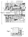
- the shaft 1, which carries the impellers of the pump stages 2, is in the housing, part of which can be seen at 3, in not shown axially fixed.
- the relief piston device is provided between a room 4 the pump which is pressurized with high pressure "H”, and a room in which lower pressure is “N” the relief piston device is provided.
- This arrangement is the relief piston 6 and the fixed Housing part 7 formed, which has a cylindrical Throttle gap 8 cooperate.
- the relief piston 6 is firmly arranged on the shaft 1. Its cross-sectional area is dimensioned so that the differential pressure acting thereon the desired Relief force results.
- the annular gap 8 has in the Usually a width of a few tenths of a millimeter and for reduction of the leakage current is of considerable axial length.
- the relief piston 10 has a smaller diameter. At the low-pressure end, it has a flange-like, radial annular projection 11 provided.
- the relief piston 10 is surrounded by the hollow-cylindrical design Throttle ring 12, with the cylindrical peripheral surface of the relief piston 10 includes an annular gap 13 which has a radial width of a few tenths of a millimeter. His cylindrical peripheral surface is in the cylindrical bore 14 of the fixed housing part 15, the game so is dimensioned so that it can be used under all operating conditions can move axially freely. It is expedient on this Side of the throttle ring, a sealing ring 16 is provided. This is not necessary if there is play between the throttle ring and the housing bore is so low that the leakage current flowing through it is negligible.
- the Throttle ring 12 has an annular projection 17 which is axially movable but non-rotatably with the fixed housing part 15 at 18 is pinned.
- the throttle gap does not need to cover the entire radial To extend the said end faces; much more the end face distance can be larger in the radially inner region be, as shown in Fig.2 at 19.
- the actual Throttle gap then begins a little further radially outwards, whereby the transition is either gradual (as in Fig. 2) or gradual can take place.
- a spring 20 that defines the radial throttle face pushing towards each other is not excluded, but generally not necessary.
- a spring can even be provided be that pushes the throttle faces apart, to prevent solid-state contact when the machine starts up.
- the throttling effect in the annular gap 13 contributes to stabilization of the radial throttle gap.
- the throttling effect in the annular gap 13 is expediently between 10 and 50% of total differential pressure.
- the leakage current in the area of the relief piston to less than half of the usual Be reduced. This can reduce the overall efficiency several points are raised.
Landscapes
- Engineering & Computer Science (AREA)
- Mechanical Engineering (AREA)
- General Engineering & Computer Science (AREA)
- Structures Of Non-Positive Displacement Pumps (AREA)
- Hydraulic Motors (AREA)
- Control Of Non-Positive-Displacement Pumps (AREA)
- Apparatuses For Bulk Treatment Of Fruits And Vegetables And Apparatuses For Preparing Feeds (AREA)
Description
- Fig.1
- einen Schnitt durch denjenigen Teil einer mehrstufigen Kreiselpumpe, der den Entlastungskolben enthält; die Darstellung in der unteren Hälfte zeigt die Anordnung des Entlastungskolbens nach herkömmlicher Technik, während die obere Hälfte die erfindungsgemäße Ausführung zeigt, und
- Fig.2
- einen Teilschnitt durch den Entlastungskolben und den zugehörigen Gehäuseteil.
Claims (2)
- Strömungsmaschine mit axial fest gelagerter Welle (1), einem darauf fest angeordneten, mit radialem Spiel in einer Gehäusebohrung (14) umlaufenden Entlastungskolben (10) und einem zwischen dem Entlastungskolben (10) und der Gehäusebohrung (14) axial beweglichen Drosselring (12), der gegenüber der Gehäusebohrung (14) abgedichtet ist und dessen Stirnfläche mit einem radialen Ringvorsprung (11) des Entlastungskolbens (10) einen radial durchströmten Drosselspalt (21) bildet, dadurch gekennzeichnet, daß der Drosselring (12) mit dem Umfang des Entlastungskolbens(10) einen als Vordrossel ausgebildeten Ringspalt (13) einschließt.
- Strömungsmaschine nach Anspruch 1, dadurch gekennzeichnet, daß der Außendurchmesser des radialen Drosselspalts (21) größer ist als der Durchmesser des mit der Gehäusebohrung (14) zusammenwirkenden Umfangs des Drosselrings (12).
Applications Claiming Priority (3)
| Application Number | Priority Date | Filing Date | Title |
|---|---|---|---|
| DE29500744U DE29500744U1 (de) | 1995-01-18 | 1995-01-18 | Strömungsmaschine mit Entlastungskolben |
| DE29500744U | 1995-01-18 | ||
| PCT/EP1996/000185 WO1996022468A1 (de) | 1995-01-18 | 1996-01-17 | Strömungsmaschine mit entlastungskolben |
Publications (2)
| Publication Number | Publication Date |
|---|---|
| EP0750720A1 EP0750720A1 (de) | 1997-01-02 |
| EP0750720B1 true EP0750720B1 (de) | 1998-12-09 |
Family
ID=8002649
Family Applications (1)
| Application Number | Title | Priority Date | Filing Date |
|---|---|---|---|
| EP96900592A Expired - Lifetime EP0750720B1 (de) | 1995-01-18 | 1996-01-17 | Strömungsmaschine mit entlastungskolben |
Country Status (4)
| Country | Link |
|---|---|
| US (1) | US5713720A (de) |
| EP (1) | EP0750720B1 (de) |
| DE (2) | DE29500744U1 (de) |
| WO (1) | WO1996022468A1 (de) |
Families Citing this family (45)
| Publication number | Priority date | Publication date | Assignee | Title |
|---|---|---|---|---|
| DE19927135A1 (de) * | 1999-06-15 | 2000-12-21 | Ksb Ag | Entlastungseinrichtung für mehrstufige Kreiselpumpen |
| DE10038586A1 (de) * | 2000-08-03 | 2002-02-14 | Ksb Ag | Axialschubausgleichseinrichtung |
| DE50206223D1 (de) * | 2001-10-22 | 2006-05-18 | Sulzer Pumpen Ag | Wellenabdichtungsanordnung für eine Pumpe zur Förderung heisser Fluide |
| DE10254041B4 (de) * | 2002-11-20 | 2011-07-07 | KSB Aktiengesellschaft, 67227 | Verfahren und Vorichtung zur Störungsfrüherkennung bei Kreiselpumpen |
| US8075668B2 (en) | 2005-03-29 | 2011-12-13 | Dresser-Rand Company | Drainage system for compressor separators |
| BRPI0716867A2 (pt) * | 2006-09-19 | 2013-10-15 | Dresser Rand Co | Vedação de tambor de separador rotativo |
| US8302779B2 (en) | 2006-09-21 | 2012-11-06 | Dresser-Rand Company | Separator drum and compressor impeller assembly |
| CA2661925C (en) | 2006-09-25 | 2015-04-28 | Gocha Chochua | Fluid deflector for fluid separator devices |
| US8061737B2 (en) | 2006-09-25 | 2011-11-22 | Dresser-Rand Company | Coupling guard system |
| US8079622B2 (en) | 2006-09-25 | 2011-12-20 | Dresser-Rand Company | Axially moveable spool connector |
| WO2008039731A2 (en) | 2006-09-25 | 2008-04-03 | Dresser-Rand Company | Access cover for pressurized connector spool |
| EP2066983B1 (de) | 2006-09-25 | 2013-12-11 | Dresser-Rand Company | Kompressorbefestigungssystem |
| EP2066422B1 (de) | 2006-09-26 | 2012-06-27 | Dresser-Rand Company | Verbesserte statische flüssigkeitstrennungsvorrichtung |
| BRPI0908051A2 (pt) | 2008-03-05 | 2015-08-11 | Dresser Rand Co | Conjunto compressor que inclui separador e bomba ejetora |
| US7922218B2 (en) | 2008-06-25 | 2011-04-12 | Dresser-Rand Company | Shear ring casing coupler device |
| US8062400B2 (en) | 2008-06-25 | 2011-11-22 | Dresser-Rand Company | Dual body drum for rotary separators |
| US8079805B2 (en) | 2008-06-25 | 2011-12-20 | Dresser-Rand Company | Rotary separator and shaft coupler for compressors |
| IT1392143B1 (it) * | 2008-09-15 | 2012-02-22 | Pompe Garbarino S P A | Pompa centrifuga multistadio con tamburo di bilanciamento idraulico a trafilamento controllato. |
| US8061970B2 (en) * | 2009-01-16 | 2011-11-22 | Dresser-Rand Company | Compact shaft support device for turbomachines |
| EP2394029A2 (de) * | 2009-02-05 | 2011-12-14 | Siemens Aktiengesellschaft | Turbomaschine mit einem ausgleichskolben |
| IT1393311B1 (it) * | 2009-03-19 | 2012-04-20 | Turboden Srl | Turbina per espansione di gas/vapore con mezzi di contrasto della spinta assiale sull'albero di uscita |
| US8087901B2 (en) | 2009-03-20 | 2012-01-03 | Dresser-Rand Company | Fluid channeling device for back-to-back compressors |
| US8210804B2 (en) | 2009-03-20 | 2012-07-03 | Dresser-Rand Company | Slidable cover for casing access port |
| US8061972B2 (en) | 2009-03-24 | 2011-11-22 | Dresser-Rand Company | High pressure casing access cover |
| EP2478229B1 (de) | 2009-09-15 | 2020-02-26 | Dresser-Rand Company | Kompakte trennvorrichtung auf basis erhöhter dichte |
| US20110097216A1 (en) * | 2009-10-22 | 2011-04-28 | Dresser-Rand Company | Lubrication system for subsea compressor |
| BR112012020085B1 (pt) | 2010-02-10 | 2020-12-01 | Dresser-Rand Company | aparelho de coleta para um separador e método de separação |
| IT1399881B1 (it) * | 2010-05-11 | 2013-05-09 | Nuova Pignone S R L | Configurazione di tamburo di bilanciamento per rotori di compressore |
| US8663483B2 (en) | 2010-07-15 | 2014-03-04 | Dresser-Rand Company | Radial vane pack for rotary separators |
| WO2012009158A2 (en) | 2010-07-15 | 2012-01-19 | Dresser-Rand Company | Enhanced in-line rotary separator |
| WO2012012018A2 (en) | 2010-07-20 | 2012-01-26 | Dresser-Rand Company | Combination of expansion and cooling to enhance separation |
| US8821362B2 (en) | 2010-07-21 | 2014-09-02 | Dresser-Rand Company | Multiple modular in-line rotary separator bundle |
| WO2012033632A1 (en) | 2010-09-09 | 2012-03-15 | Dresser-Rand Company | Flush-enabled controlled flow drain |
| WO2013109235A2 (en) | 2010-12-30 | 2013-07-25 | Dresser-Rand Company | Method for on-line detection of resistance-to-ground faults in active magnetic bearing systems |
| US8994237B2 (en) | 2010-12-30 | 2015-03-31 | Dresser-Rand Company | Method for on-line detection of liquid and potential for the occurrence of resistance to ground faults in active magnetic bearing systems |
| WO2012138545A2 (en) | 2011-04-08 | 2012-10-11 | Dresser-Rand Company | Circulating dielectric oil cooling system for canned bearings and canned electronics |
| EP2715167B1 (de) | 2011-05-27 | 2017-08-30 | Dresser-Rand Company | Segmentiertes auslauflager für magnetlagersysteme |
| US8851756B2 (en) | 2011-06-29 | 2014-10-07 | Dresser-Rand Company | Whirl inhibiting coast-down bearing for magnetic bearing systems |
| DE102013223806A1 (de) * | 2013-11-21 | 2015-05-21 | Ksb Aktiengesellschaft | Entlastungseinrichtung |
| DE102014016476A1 (de) * | 2014-11-07 | 2016-05-12 | Man Diesel & Turbo Se | Strömungsmaschine |
| EP3412915B1 (de) | 2017-06-09 | 2019-12-25 | Xylem Europe GmbH | Selbsteinstellendes trommelsystem |
| JP2022068479A (ja) * | 2020-10-22 | 2022-05-10 | 三菱重工コンプレッサ株式会社 | 回転機械及びギアド圧縮機 |
| ES2994915T3 (en) | 2021-01-13 | 2025-02-04 | Sulzer Management Ag | Rotary pump with axial thrust balancing drum and regulation of a leakage flow |
| US11971046B2 (en) * | 2022-02-11 | 2024-04-30 | Sulzer Management Ag | Rotary pump for conveying a fluid |
| DE102023114849A1 (de) * | 2023-06-06 | 2024-12-12 | KSB SE & Co. KGaA | Kreiselpumpenanordnung |
Family Cites Families (7)
| Publication number | Priority date | Publication date | Assignee | Title |
|---|---|---|---|---|
| US2221225A (en) * | 1938-04-16 | 1940-11-12 | Pacific Pump Works | Balancing and leakage device for centrifugal pumps |
| DE1453787A1 (de) * | 1962-05-16 | 1969-05-08 | Klein Schanzlin & Becker Ag | Achsschubentlastungseinrichtung fuer Kreiselpumpen |
| CH669241A5 (de) * | 1985-11-27 | 1989-02-28 | Sulzer Ag | Axialschub-ausgleichsvorrichtung fuer fluessigkeitspumpe. |
| US5104284A (en) * | 1990-12-17 | 1992-04-14 | Dresser-Rand Company | Thrust compensating apparatus |
| CH684495A5 (de) * | 1991-09-04 | 1994-09-30 | Escher Wyss Ag | Turbomaschine. |
| DE4313455A1 (de) * | 1993-04-24 | 1994-10-27 | Klein Schanzlin & Becker Ag | Radialer Spalt, beispielsweise einer Strömungsmaschine |
| FI940630A7 (fi) * | 1994-02-11 | 1995-08-12 | Ahlstroem Pumput Oy | Keskipakopumppu |
-
1995
- 1995-01-18 DE DE29500744U patent/DE29500744U1/de not_active Expired - Lifetime
-
1996
- 1996-01-17 WO PCT/EP1996/000185 patent/WO1996022468A1/de not_active Ceased
- 1996-01-17 DE DE59600941T patent/DE59600941D1/de not_active Expired - Lifetime
- 1996-01-17 EP EP96900592A patent/EP0750720B1/de not_active Expired - Lifetime
- 1996-01-17 US US08/704,599 patent/US5713720A/en not_active Expired - Lifetime
Also Published As
| Publication number | Publication date |
|---|---|
| DE29500744U1 (de) | 1996-05-15 |
| US5713720A (en) | 1998-02-03 |
| EP0750720A1 (de) | 1997-01-02 |
| DE59600941D1 (de) | 1999-01-21 |
| WO1996022468A1 (de) | 1996-07-25 |
Similar Documents
| Publication | Publication Date | Title |
|---|---|---|
| EP0750720B1 (de) | Strömungsmaschine mit entlastungskolben | |
| DE2146026C2 (de) | Wellendichtungsanordnung | |
| EP0256221B1 (de) | Anordnung zur Abdichtung einer Stange | |
| DE1475886C3 (de) | Gleitringdichtung | |
| DE2737788C2 (de) | ||
| DE3201860C2 (de) | Berührungsfrei arbeitende Dichtung zwischen relativ zueinander umlaufenden Maschinenteilen | |
| EP0641421B1 (de) | Schwimmringdichtung | |
| DE4303050B4 (de) | Gleitringdichtung | |
| DE69407080T2 (de) | Seitenkanalpumpe | |
| EP1019637B1 (de) | Radialer schwenkmotor | |
| DE1934448C2 (de) | ||
| EP0622525B1 (de) | Bauteilanordnung mit einem radialen Spalt | |
| DE19722870C2 (de) | Gasgeschmierte Gleitringdichtung | |
| DE1525427B1 (de) | Wellendichtung mit zwei Gleichringdichtungen | |
| DE2608887A1 (de) | Verteilerventil an einer hydraulischen kreiskolbenmaschine | |
| DE1812251B2 (de) | Flügelzellenpumpe | |
| WO1990010161A1 (de) | Axialschubentlastungseinrichtung | |
| DE1650400A1 (de) | Drehschieber | |
| EP1097306B1 (de) | Schwenkmotor | |
| DE1812635A1 (de) | Radialkolbenpumpe | |
| DE1956632A1 (de) | Spaltrohrmotor-Kreiselpumpenaggregat | |
| DE1528615A1 (de) | Hydrostatische Radialkolbeneinheit | |
| DE2025636A1 (de) | Hydrostatisches Lager | |
| EP1305525B1 (de) | Axialschubausgleichseinrichtung | |
| DE102023206372A1 (de) | Schieberventil mit Ringsteg im Bereich einer stetig verstellbaren Blende zur Strömungswiderstandminimierung |
Legal Events
| Date | Code | Title | Description |
|---|---|---|---|
| PUAI | Public reference made under article 153(3) epc to a published international application that has entered the european phase |
Free format text: ORIGINAL CODE: 0009012 |
|
| 17P | Request for examination filed |
Effective date: 19960819 |
|
| AK | Designated contracting states |
Kind code of ref document: A1 Designated state(s): CH DE FR GB IT LI NL |
|
| GRAG | Despatch of communication of intention to grant |
Free format text: ORIGINAL CODE: EPIDOS AGRA |
|
| GRAG | Despatch of communication of intention to grant |
Free format text: ORIGINAL CODE: EPIDOS AGRA |
|
| GRAH | Despatch of communication of intention to grant a patent |
Free format text: ORIGINAL CODE: EPIDOS IGRA |
|
| 17Q | First examination report despatched |
Effective date: 19980428 |
|
| GRAH | Despatch of communication of intention to grant a patent |
Free format text: ORIGINAL CODE: EPIDOS IGRA |
|
| GRAA | (expected) grant |
Free format text: ORIGINAL CODE: 0009210 |
|
| RAP1 | Party data changed (applicant data changed or rights of an application transferred) |
Owner name: STERLING INDUSTRY CONSULT GMBH |
|
| AK | Designated contracting states |
Kind code of ref document: B1 Designated state(s): CH DE FR GB IT LI NL |
|
| REG | Reference to a national code |
Ref country code: CH Ref legal event code: EP |
|
| REG | Reference to a national code |
Ref country code: CH Ref legal event code: NV Representative=s name: TROESCH SCHEIDEGGER WERNER AG |
|
| REF | Corresponds to: |
Ref document number: 59600941 Country of ref document: DE Date of ref document: 19990121 |
|
| ET | Fr: translation filed | ||
| ITF | It: translation for a ep patent filed | ||
| GBT | Gb: translation of ep patent filed (gb section 77(6)(a)/1977) |
Effective date: 19990309 |
|
| PLBE | No opposition filed within time limit |
Free format text: ORIGINAL CODE: 0009261 |
|
| STAA | Information on the status of an ep patent application or granted ep patent |
Free format text: STATUS: NO OPPOSITION FILED WITHIN TIME LIMIT |
|
| 26N | No opposition filed | ||
| REG | Reference to a national code |
Ref country code: GB Ref legal event code: IF02 |
|
| PGFP | Annual fee paid to national office [announced via postgrant information from national office to epo] |
Ref country code: CH Payment date: 20100125 Year of fee payment: 15 |
|
| PGFP | Annual fee paid to national office [announced via postgrant information from national office to epo] |
Ref country code: IT Payment date: 20100123 Year of fee payment: 15 Ref country code: FR Payment date: 20100209 Year of fee payment: 15 |
|
| PGFP | Annual fee paid to national office [announced via postgrant information from national office to epo] |
Ref country code: GB Payment date: 20100121 Year of fee payment: 15 |
|
| PGFP | Annual fee paid to national office [announced via postgrant information from national office to epo] |
Ref country code: NL Payment date: 20100121 Year of fee payment: 15 |
|
| REG | Reference to a national code |
Ref country code: NL Ref legal event code: V1 Effective date: 20110801 |
|
| REG | Reference to a national code |
Ref country code: CH Ref legal event code: PL |
|
| GBPC | Gb: european patent ceased through non-payment of renewal fee |
Effective date: 20110117 |
|
| REG | Reference to a national code |
Ref country code: FR Ref legal event code: ST Effective date: 20110930 |
|
| PG25 | Lapsed in a contracting state [announced via postgrant information from national office to epo] |
Ref country code: CH Free format text: LAPSE BECAUSE OF NON-PAYMENT OF DUE FEES Effective date: 20110131 Ref country code: LI Free format text: LAPSE BECAUSE OF NON-PAYMENT OF DUE FEES Effective date: 20110131 Ref country code: FR Free format text: LAPSE BECAUSE OF NON-PAYMENT OF DUE FEES Effective date: 20110131 |
|
| PG25 | Lapsed in a contracting state [announced via postgrant information from national office to epo] |
Ref country code: GB Free format text: LAPSE BECAUSE OF NON-PAYMENT OF DUE FEES Effective date: 20110117 |
|
| PG25 | Lapsed in a contracting state [announced via postgrant information from national office to epo] |
Ref country code: IT Free format text: LAPSE BECAUSE OF NON-PAYMENT OF DUE FEES Effective date: 20110117 Ref country code: NL Free format text: LAPSE BECAUSE OF NON-PAYMENT OF DUE FEES Effective date: 20110801 |
|
| PGFP | Annual fee paid to national office [announced via postgrant information from national office to epo] |
Ref country code: DE Payment date: 20150629 Year of fee payment: 20 |
|
| REG | Reference to a national code |
Ref country code: DE Ref legal event code: R071 Ref document number: 59600941 Country of ref document: DE |