EP0749931B1 - Traction sheave elevator - Google Patents
Traction sheave elevator Download PDFInfo
- Publication number
- EP0749931B1 EP0749931B1 EP96109413A EP96109413A EP0749931B1 EP 0749931 B1 EP0749931 B1 EP 0749931B1 EP 96109413 A EP96109413 A EP 96109413A EP 96109413 A EP96109413 A EP 96109413A EP 0749931 B1 EP0749931 B1 EP 0749931B1
- Authority
- EP
- European Patent Office
- Prior art keywords
- elevator
- traction sheave
- counterweight
- car
- shaft
- Prior art date
- Legal status (The legal status is an assumption and is not a legal conclusion. Google has not performed a legal analysis and makes no representation as to the accuracy of the status listed.)
- Expired - Lifetime
Links
Images


Classifications
-
- B—PERFORMING OPERATIONS; TRANSPORTING
- B66—HOISTING; LIFTING; HAULING
- B66B—ELEVATORS; ESCALATORS OR MOVING WALKWAYS
- B66B7/00—Other common features of elevators
-
- B—PERFORMING OPERATIONS; TRANSPORTING
- B66—HOISTING; LIFTING; HAULING
- B66B—ELEVATORS; ESCALATORS OR MOVING WALKWAYS
- B66B11/00—Main component parts of lifts in, or associated with, buildings or other structures
- B66B11/04—Driving gear ; Details thereof, e.g. seals
- B66B11/08—Driving gear ; Details thereof, e.g. seals with hoisting rope or cable operated by frictional engagement with a winding drum or sheave
Definitions
- the present invention relates to a traction sheave elevator as defined in the preamble of claim 1.
- traction sheave elevator of the invention is characterized by what is said in the characterization part of claim 1.
- Other embodiments of the invention are characterized by the features presented in the other claims.
- the invention provides various advantages, including the following:
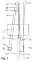
- Fig. 1 is a diagrammatic representation of a traction sheave elevator as provided by the invention.
- the elevator is a traction sheave elevator with machinery below.
- the elevator car 1 and counterweight 2 are suspended on the hoisting ropes 3 of the elevator.
- the suspension of the elevator car 1 from the hoisting ropes 3 is preferably essentially centric or symmetric relative to the vertical line passing through the centre of gravity of the elevator car 1.
- the suspension of the counter-weight 2 from the hoisting ropes 3 is preferably essentially centric or symmetric relative to the vertical line passing through the centre of gravity of the counter-weight 2.
- the drive machine unit 6 of the elevator is placed in the elevator shaft, preferably in the lower part of the elevator shaft, and the hoisting ropes 3 are passed to the car 1 and counterweight 2 via diverting pulleys 4,5 placed in the upper part of the elevator shaft.
- the hoisting ropes consist of a number of collateral ropes, usually at least three.
- the elevator car 1 and counterweight 2 travel in the elevator shaft along elevator and counterweight guide rails 10,11 guiding them.
- the hoisting ropes run as follows: One end of the ropes is fixed to an anchorage 12 at the top part of the shaft, from where the ropes go downward to the counterweight.
- the counterweight is suspended on the ropes 3 using a diverting pulley 9. From the counterweight, the ropes go up again to a first diverting pulley 5, which is mounted on an elevator guide rail 10, and from the diverting pulley 5 further to the traction sheave 7 driven by the drive machinery 6.
- the ropes From the traction sheave, the ropes go upward to a second diverting pulley 4 and round this pulley back down to the diverting pulleys 8 of the elevator car, passing below the car, and then further up to an anchorage 13 at the top part of the shaft, where the other end of the ropes is fixed.
- the elevator car 1 is suspended on the hoisting ropes 3 by means of diverting pulleys 8.
- one or more of the rope portions between the diverting pulleys or between the diverting pulleys and the traction sheave 7 or between the diverting pulleys and the rope anchorages 12,13 can run in a direction differing from the exact vertical direction, making it easy to provide a sufficient distance between different rope portions or between the hoisting ropes and the other elevator components.
- diverting pulleys 4,5 of which the upper one has a larger diameter than the lower one.
- the traction sheave 7 and the hoisting machinery 6 itself lie aside from the paths of both the elevator car 1 and the counterweight 2, so they can easily be placed at almost any height in the elevator shaft below the diverting pulleys 4,5.
- the minimum height of the elevator shaft is only determined by the lengths of the paths of the elevator car and counterweight and the safety distances required above and below them.
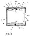
- Fig. 2 illustrates the placement of the main elevator components in the cross-section of the elevator shaft 15.
- the machinery 6 together with the traction sheave 7 is completely separated from the car 1 and counterweight.
- the machinery with the traction sheave and the counterweight are placed on the same side of the elevator car 1 between the projection of the elevator car and the shaft wall.
- the machinery is located on the opposite side of the plane of the car guide rails 10 in the shaft 15 and it is fixed to the shaft wall or floor. Mounting the machinery on a wall or on the floor provides an advantage, because if the machinery were mounted on the same guide rail as the diverting pulleys 4,5, the guide rail would have to be of a stronger design.
- Individual hoisting ropes 3 are represented by the cross-sections of the rope portions going from the diverting pulleys and traction sheave in the up and down directions.
- the car is provided with a car door 18 and the wall of the elevator shaft 15 with a landing door 17 to provide access from the landing to the elevator car 1.
- the machinery 6 Being flat in the direction of the axis of rotation of the traction sheave 7, the machinery 6 provides a space saving in the cross-sectional lay-out of the elevator shaft, because the gap between the car 1 and the wall of the shaft 15 required by such a machinery is not larger than the space needed for the counterweight.
- the diverting pulley 5 supporting the counterweight is mounted on a counterweight guide rail 11, then it is easy to place the counterweight 2 and machinery 6 on opposite sides of the elevator car 1 in the cross-sectional lay-out of the elevator shaft 15.
- a lay-out like this may be needed e.g. when several elevators are mounted in shafts placed side by side and/or back to back.
- both the diverting pulleys 4,5 and the rope anchorages 12,13 are supported by the guide rails, it is substantially not necessary to provide any other support to carry the weight of the counterweight and elevator car, so in this respect the attachments to the shaft wall can be relatively light and no special requirements relating to supporting the weight of the elevator car and counterweight need to be imposed on the construction of the shaft.
- FIG. 3 Another traction sheave elevator according to the invention is presented in the form of a diagram in Fig. 3. This is a traction sheave elevator with machinery below.
- the elevator car 101 and counterweight 102 are suspended on the hoisting ropes 103 of the elevator.
- the drive machine unit 106 of the elevator is placed in the elevator shaft, preferably in the lower part of the shaft, and the hoisting ropes 103 are passed via diverting pulleys 104,105 to the car 101 and counterweight 102.
- the diverting pulleys 104,105 are placed side by side and preferably separately mounted with bearings on the same axle so that they can rotate independently of each other.
- the hoisting ropes 103 consist of at least three parallel ropes.
- the elevator car 101 and the counterweight 102 travel in the elevator shaft along car and counterweight guide rails 110,111.
- the passage of the hoisting ropes 103 is as follows: One end of the ropes is fixed to an anchorage 112 in the top part of the shaft, from where the ropes go downward to the counterweight 102.
- the counterweight is suspended on the ropes 103 using a diverting pulley 109. From the counterweight, the ropes go up again to a first diverting pulley 105, which is mounted on an elevator guide rail 110, and from the diverting pulley 105 further to the traction sheave 107 driven by the drive machinery 106.
- the ropes From the traction sheave, the ropes go upward to a second diverting pulley 104 and round this pulley back down to the diverting pulleys 108 of the elevator car, passing below the car, and then further up to an anchorage 113 at the top part of the shaft, where the other end of the ropes is fixed.
- the elevator car 101 is suspended on the hoisting ropes 103 by means of diverting pulleys 108.
- one or more of the rope portions between the diverting pulleys or betweeen the diverting pulleys and the traction sheave 107 or between the diverting pulleys and the rope anchorages 112,113 can run in a direction differing from the exact vertical direction, making it easy to provide a sufficient distance between different rope portions or between the hoisting ropes and the other elevator components.
- the traction sheave 107 and the hoisting machinery 106 itself lie aside from the paths of both the elevator car 101 and the counterweight 102, so they can easily be placed at almost any height in the elevator shaft below the diverting pulleys 104,105. As the machinery is not placed directly above or below the counterweight or elevator car, a saving can be achieved in the height of the elevator shaft.
- a preferred embodiment is one in which that portion of the weight of the elevator car and counterweight which is supported by the diverting pulleys 4,5,104,105 is passed down via an elevator guide rail.
- the rope portions going from the traction sheave 7 to the counterweight and to the elevator car meet the diverting pulleys 4,5 from the same side (from the left in Fig. 1) of the plane between the elevator guide rails, so the weight of elevator car and counterweight is naturally applied to the diverting pulleys 8 from the opposite side of the plane between the elevator guide rails.
- the elevator in Fig. 1 the rope portions going from the traction sheave 7 to the counterweight and to the elevator car meet the diverting pulleys 4,5 from the same side (from the left in Fig. 1) of the plane between the elevator guide rails, so the weight of elevator car and counterweight is naturally applied to the diverting pulleys 8 from the opposite side of the plane between the elevator guide rails.
- the rope portions going from the traction sheave 107 to the counterweight and to the elevator car meet the diverting pulleys 104,105 from opposite sides of the plane between the elevator guide rails.
- the suspension of the elevator car and counterweight on the diverting pulleys 8 is a mirror image relative to the plane between the elevator guide rails as compared to the situation in Fig. 1. In this way, by slightly altering the rope passage, the rope suspension of the elevator car can be centered at a point where an advantageous support effect on the car is achieved.
- Fig. 4 illustrates the placement of the main components of an elevator as presented by Fig. 3 in the cross-section of the elevator shaft 15.
- the machinery 106 with the traction sheave 107 is a completely separate unit.
- Individual hoisting ropes 103 are represented by the cross-sections of the rope portions going in the up and down directions from the diverting pulleys and traction sheave.
- the car is provided with a car door 18 and the wall of the elevator shaft 15 with a landing door 17 to provide access from the landing to the elevator car 101.
- the machinery 106 Being flat in the direction of the axis of rotation of the traction sheave 107, the machinery 106 provides a space saving in the cross-sectional lay-out of the elevator shaft, because the gap between the car 101 and the wall of the shaft 15 required by such a machinery is not larger than the space needed for the counterweight.
Applications Claiming Priority (2)
| Application Number | Priority Date | Filing Date | Title |
|---|---|---|---|
| FI953154 | 1995-06-22 | ||
| FI953154A FI100791B (fi) | 1995-06-22 | 1995-06-22 | Vetopyörähissi |
Publications (3)
| Publication Number | Publication Date |
|---|---|
| EP0749931A2 EP0749931A2 (en) | 1996-12-27 |
| EP0749931A3 EP0749931A3 (en) | 1997-02-26 |
| EP0749931B1 true EP0749931B1 (en) | 1998-10-07 |
Family
ID=8543677
Family Applications (1)
| Application Number | Title | Priority Date | Filing Date |
|---|---|---|---|
| EP96109413A Expired - Lifetime EP0749931B1 (en) | 1995-06-22 | 1996-06-12 | Traction sheave elevator |
Country Status (9)
| Country | Link |
|---|---|
| US (1) | US5823298A (fi) |
| EP (1) | EP0749931B1 (fi) |
| JP (1) | JP2688348B2 (fi) |
| KR (1) | KR100424162B1 (fi) |
| CN (1) | CN1093502C (fi) |
| DE (1) | DE69600749T2 (fi) |
| ES (1) | ES2123317T3 (fi) |
| FI (1) | FI100791B (fi) |
| IN (1) | IN190211B (fi) |
Families Citing this family (37)
| Publication number | Priority date | Publication date | Assignee | Title |
|---|---|---|---|---|
| FI100791B (fi) * | 1995-06-22 | 1998-02-27 | Kone Oy | Vetopyörähissi |
| DE19712646C2 (de) * | 1997-03-26 | 2000-07-13 | Heinzerling Gmbh | Seilaufzug |
| DE19752232C2 (de) * | 1997-03-26 | 2001-06-21 | Heinzerling Gmbh | Seilaufzug mit in den Aufzugschacht hineinragenden Betonsockel |
| US5931265A (en) | 1997-03-27 | 1999-08-03 | Otis Elevator Company | Rope climbing elevator |
| US6860367B1 (en) | 1998-09-29 | 2005-03-01 | Otis Elevator Company | Elevator system having drive motor located below the elevator car |
| US6138799A (en) * | 1998-09-30 | 2000-10-31 | Otis Elevator Company | Belt-climbing elevator having drive in counterweight |
| US7874404B1 (en) | 1998-09-29 | 2011-01-25 | Otis Elevator Company | Elevator system having drive motor located between elevator car and hoistway sidewall |
| US7299896B1 (en) | 1998-09-29 | 2007-11-27 | Otis Elevator Company | Elevator system having drive motor located adjacent to hoistway door |
| DE29924761U1 (de) | 1998-02-26 | 2005-06-23 | Otis Elevator Co., Farmington | Zugelement für einen Aufzug |
| MY121775A (en) | 1998-04-28 | 2006-02-28 | Toshiba Kk | Traction type elevator apparatus |
| KR100415749B1 (ko) * | 1998-06-30 | 2004-01-24 | 미쓰비시덴키 가부시키가이샤 | 엘리베이터 장치 |
| US6305499B1 (en) | 1998-09-30 | 2001-10-23 | Otis Elevator Company | Drum drive elevator using flat belt |
| US6848543B2 (en) | 1998-10-30 | 2005-02-01 | Otis Elevator Company | Single wall interface traction elevator |
| US6478117B2 (en) | 1998-10-30 | 2002-11-12 | Otis Elevator Company | Elevator system having governor positioned under controller in hoistway at top floor level |
| US6039152A (en) * | 1998-10-30 | 2000-03-21 | Otis Elevator Company | Elevator system with controller located under elevator landing |
| US6085874A (en) * | 1998-12-22 | 2000-07-11 | Otis Elevator Company | Rail-climbing elevator counterweight having flat machines |
| US6202793B1 (en) | 1998-12-22 | 2001-03-20 | Richard N. Fargo | Elevator machine with counter-rotating rotors |
| US7246688B2 (en) | 1998-12-23 | 2007-07-24 | Otis Elevator Company | Elevator door system |
| JP3528668B2 (ja) * | 1999-03-24 | 2004-05-17 | 株式会社日立製作所 | エレベータの制御装置 |
| KR100351275B1 (ko) | 1999-07-19 | 2002-09-09 | 엘지 오티스 엘리베이터 유한회사 | 머신룸 레스 엘리베이터 |
| JP2001048442A (ja) * | 1999-08-16 | 2001-02-20 | Hitachi Building Systems Co Ltd | エレベータ |
| DE69936399T2 (de) * | 1999-12-06 | 2008-02-28 | Mitsubishi Denki K.K. | Aufzugsgeraet |
| EP1308411B1 (en) * | 2000-05-22 | 2011-05-18 | Mitsubishi Denki Kabushiki Kaisha | Elevator device |
| FI118732B (fi) | 2000-12-08 | 2008-02-29 | Kone Corp | Hissi |
| JP2002362849A (ja) * | 2001-06-08 | 2002-12-18 | Mitsubishi Electric Corp | エレベーター |
| DK1397304T3 (da) * | 2001-06-21 | 2008-08-04 | Kone Corp | Elevator |
| US9573792B2 (en) | 2001-06-21 | 2017-02-21 | Kone Corporation | Elevator |
| ITMI20012558A1 (it) * | 2001-12-04 | 2003-06-04 | L A Consulting S A S Di Sara F | Ascensore con cabina guidata in un vano corsa, senza locale del macchinario |
| FI119234B (fi) | 2002-01-09 | 2008-09-15 | Kone Corp | Hissi |
| JP2004075270A (ja) * | 2002-08-14 | 2004-03-11 | Toshiba Elevator Co Ltd | エレベータ装置 |
| CN100457592C (zh) * | 2004-06-07 | 2009-02-04 | 三菱电机株式会社 | 电梯装置 |
| JP4732344B2 (ja) | 2004-07-12 | 2011-07-27 | 三菱電機株式会社 | エレベータ装置 |
| EP1832543B1 (en) * | 2004-12-27 | 2014-03-26 | Mitsubishi Denki Kabushiki Kaisha | Elevator apparatus |
| KR100872928B1 (ko) * | 2007-03-26 | 2008-12-08 | 미쓰비시덴키 가부시키가이샤 | 엘리베이터 장치 |
| DE112012006547B4 (de) * | 2012-06-18 | 2019-08-14 | Mitsubishi Electric Corp. | Aufzug und Aufzugsüberholungsverfahren |
| JP6477255B2 (ja) * | 2015-05-27 | 2019-03-06 | フジテック株式会社 | 機械室レスエレベータ |
| CN106115414A (zh) * | 2016-08-31 | 2016-11-16 | 天津市奥瑞克电梯有限公司 | 新型无机房电梯布置 |
Family Cites Families (15)
| Publication number | Priority date | Publication date | Assignee | Title |
|---|---|---|---|---|
| DE1251926B (de) * | 1965-04-28 | 1967-10-12 | Haushahn Fa C | Aufzug fuer hohe, seitlichen Ausbiegungen unterliegende Tuerme |
| FR1451792A (fr) * | 1965-10-27 | 1966-01-07 | Installation d'ascenseur avec entraînement par poulie motrice | |
| IT1133556B (it) * | 1980-01-21 | 1986-07-09 | Mupi Spa | Apparecchio di proiezione ottica e riproduzione sonora con pellicola continua e testina di lettura a monte di un rocchetto di avanzamento |
| AU580453B2 (en) * | 1985-11-04 | 1989-01-12 | Johns Perry Industries Pty. Ltd. | Lift sheave |
| JPH0745315B2 (ja) * | 1988-08-26 | 1995-05-17 | 三菱電機株式会社 | 巻上機 |
| DE3922798C1 (fi) * | 1989-07-11 | 1990-09-20 | Gerhard Ing.(Grad.) 8060 Dachau De Schlosser | |
| FI894039A (fi) * | 1989-08-29 | 1991-03-02 | Kone Oy | Placering av en driftsenhet foer en his. |
| JP2666622B2 (ja) * | 1991-09-18 | 1997-10-22 | 株式会社ダイフク | 昇降設備 |
| EP0565516A1 (de) * | 1992-04-09 | 1993-10-13 | Werner Mag. Dr. Hagel | Aufzug |
| FI93631C (fi) * | 1993-01-11 | 1995-05-10 | Kone Oy | Vastapainoon sijoitettu hissimoottori |
| FI93632C (fi) * | 1993-06-28 | 1995-05-10 | Kone Oy | Alakoneistoinen vetopyörähissi |
| FI94123C (fi) * | 1993-06-28 | 1995-07-25 | Kone Oy | Vetopyörähissi |
| FI98209C (fi) * | 1994-05-04 | 1997-05-12 | Kone Oy | Vetopyörähissi, nostoyksikkö ja koneistotila |
| FI100791B (fi) * | 1995-06-22 | 1998-02-27 | Kone Oy | Vetopyörähissi |
| KR101251926B1 (ko) * | 2011-10-14 | 2013-04-08 | 황귀순 | 프로브 유닛 |
-
1995
- 1995-06-22 FI FI953154A patent/FI100791B/fi not_active IP Right Cessation
-
1996
- 1996-06-11 IN IN1085CA1996 patent/IN190211B/en unknown
- 1996-06-12 EP EP96109413A patent/EP0749931B1/en not_active Expired - Lifetime
- 1996-06-12 ES ES96109413T patent/ES2123317T3/es not_active Expired - Lifetime
- 1996-06-12 DE DE69600749T patent/DE69600749T2/de not_active Expired - Lifetime
- 1996-06-19 US US08/666,836 patent/US5823298A/en not_active Expired - Lifetime
- 1996-06-20 KR KR1019960022495A patent/KR100424162B1/ko not_active IP Right Cessation
- 1996-06-21 CN CN96108637A patent/CN1093502C/zh not_active Expired - Lifetime
- 1996-06-24 JP JP8181695A patent/JP2688348B2/ja not_active Expired - Lifetime
Also Published As
| Publication number | Publication date |
|---|---|
| KR970001191A (ko) | 1997-01-21 |
| ES2123317T3 (es) | 1999-01-01 |
| CN1093502C (zh) | 2002-10-30 |
| KR100424162B1 (ko) | 2004-09-04 |
| US5823298A (en) | 1998-10-20 |
| EP0749931A3 (en) | 1997-02-26 |
| DE69600749T2 (de) | 1999-03-04 |
| EP0749931A2 (en) | 1996-12-27 |
| JPH09165163A (ja) | 1997-06-24 |
| IN190211B (fi) | 2003-07-05 |
| FI953154A0 (fi) | 1995-06-22 |
| CN1143042A (zh) | 1997-02-19 |
| FI953154A (fi) | 1996-12-23 |
| DE69600749D1 (de) | 1998-11-12 |
| FI100791B (fi) | 1998-02-27 |
| JP2688348B2 (ja) | 1997-12-10 |
Similar Documents
| Publication | Publication Date | Title |
|---|---|---|
| EP0749931B1 (en) | Traction sheave elevator | |
| EP1112955B1 (en) | Traction sheave elevator | |
| US5469937A (en) | Traction sheave elevator with drive machine below | |
| FI94123C (fi) | Vetopyörähissi | |
| AU760720B2 (en) | Traction sheave elevator | |
| EP0710618B1 (en) | Traction sheave elevator | |
| US5076398A (en) | Rope suspension system for an elevator | |
| US20040035645A1 (en) | Elevator | |
| JP4312604B2 (ja) | エレベータ装置 | |
| JP2004525837A (ja) | エレベータ巻上ロープの細い高強度ワイヤ | |
| JP2004521050A (ja) | エレベータ | |
| ZA200202035B (en) | Cable elevator. | |
| GB2352221A (en) | Elevator system | |
| JP4934941B2 (ja) | エレベータ装置 | |
| US6302239B1 (en) | Elevator apparatus with hoisting machine beneath elevator car | |
| KR101014215B1 (ko) | 엘리베이터를 구성하기 위한 방법 및 엘리베이터 배송을위한 시스템 | |
| US7448474B2 (en) | Method for making an elevator and system for elevator delivery |
Legal Events
| Date | Code | Title | Description |
|---|---|---|---|
| PUAI | Public reference made under article 153(3) epc to a published international application that has entered the european phase |
Free format text: ORIGINAL CODE: 0009012 |
|
| AK | Designated contracting states |
Kind code of ref document: A2 Designated state(s): DE ES FR IT |
|
| PUAL | Search report despatched |
Free format text: ORIGINAL CODE: 0009013 |
|
| AK | Designated contracting states |
Kind code of ref document: A3 Designated state(s): DE ES FR IT |
|
| 17P | Request for examination filed |
Effective date: 19970728 |
|
| GRAG | Despatch of communication of intention to grant |
Free format text: ORIGINAL CODE: EPIDOS AGRA |
|
| GRAG | Despatch of communication of intention to grant |
Free format text: ORIGINAL CODE: EPIDOS AGRA |
|
| GRAH | Despatch of communication of intention to grant a patent |
Free format text: ORIGINAL CODE: EPIDOS IGRA |
|
| 17Q | First examination report despatched |
Effective date: 19980312 |
|
| GRAH | Despatch of communication of intention to grant a patent |
Free format text: ORIGINAL CODE: EPIDOS IGRA |
|
| GRAA | (expected) grant |
Free format text: ORIGINAL CODE: 0009210 |
|
| RAP1 | Party data changed (applicant data changed or rights of an application transferred) |
Owner name: KONE CORPORATION |
|
| AK | Designated contracting states |
Kind code of ref document: B1 Designated state(s): DE ES FR IT |
|
| REF | Corresponds to: |
Ref document number: 69600749 Country of ref document: DE Date of ref document: 19981112 |
|
| ET | Fr: translation filed | ||
| REG | Reference to a national code |
Ref country code: ES Ref legal event code: FG2A Ref document number: 2123317 Country of ref document: ES Kind code of ref document: T3 |
|
| PLBQ | Unpublished change to opponent data |
Free format text: ORIGINAL CODE: EPIDOS OPPO |
|
| PLBI | Opposition filed |
Free format text: ORIGINAL CODE: 0009260 |
|
| PLBF | Reply of patent proprietor to notice(s) of opposition |
Free format text: ORIGINAL CODE: EPIDOS OBSO |
|
| 26 | Opposition filed |
Opponent name: SCHMITT & SOHN GMBH & CO. AUFZUGSWERKE Effective date: 19990626 |
|
| PLBF | Reply of patent proprietor to notice(s) of opposition |
Free format text: ORIGINAL CODE: EPIDOS OBSO |
|
| PLBF | Reply of patent proprietor to notice(s) of opposition |
Free format text: ORIGINAL CODE: EPIDOS OBSO |
|
| PLBO | Opposition rejected |
Free format text: ORIGINAL CODE: EPIDOS REJO |
|
| APAC | Appeal dossier modified |
Free format text: ORIGINAL CODE: EPIDOS NOAPO |
|
| APAE | Appeal reference modified |
Free format text: ORIGINAL CODE: EPIDOS REFNO |
|
| APAC | Appeal dossier modified |
Free format text: ORIGINAL CODE: EPIDOS NOAPO |
|
| APBU | Appeal procedure closed |
Free format text: ORIGINAL CODE: EPIDOSNNOA9O |
|
| PLBN | Opposition rejected |
Free format text: ORIGINAL CODE: 0009273 |
|
| STAA | Information on the status of an ep patent application or granted ep patent |
Free format text: STATUS: OPPOSITION REJECTED |
|
| 27O | Opposition rejected |
Effective date: 20031007 |
|
| APAH | Appeal reference modified |
Free format text: ORIGINAL CODE: EPIDOSCREFNO |
|
| REG | Reference to a national code |
Ref country code: FR Ref legal event code: PLFP Year of fee payment: 20 |
|
| PGFP | Annual fee paid to national office [announced via postgrant information from national office to epo] |
Ref country code: DE Payment date: 20150619 Year of fee payment: 20 Ref country code: ES Payment date: 20150619 Year of fee payment: 20 |
|
| PGFP | Annual fee paid to national office [announced via postgrant information from national office to epo] |
Ref country code: IT Payment date: 20150623 Year of fee payment: 20 Ref country code: FR Payment date: 20150619 Year of fee payment: 20 |
|
| REG | Reference to a national code |
Ref country code: DE Ref legal event code: R071 Ref document number: 69600749 Country of ref document: DE |
|
| REG | Reference to a national code |
Ref country code: ES Ref legal event code: FD2A Effective date: 20160926 |
|
| PG25 | Lapsed in a contracting state [announced via postgrant information from national office to epo] |
Ref country code: ES Free format text: LAPSE BECAUSE OF EXPIRATION OF PROTECTION Effective date: 20160613 |