EP0749795B1 - Outil de perçage - Google Patents
Outil de perçage Download PDFInfo
- Publication number
- EP0749795B1 EP0749795B1 EP96109375A EP96109375A EP0749795B1 EP 0749795 B1 EP0749795 B1 EP 0749795B1 EP 96109375 A EP96109375 A EP 96109375A EP 96109375 A EP96109375 A EP 96109375A EP 0749795 B1 EP0749795 B1 EP 0749795B1
- Authority
- EP
- European Patent Office
- Prior art keywords
- drilling tool
- recess
- tool according
- drill shank
- drill
- Prior art date
- Legal status (The legal status is an assumption and is not a legal conclusion. Google has not performed a legal analysis and makes no representation as to the accuracy of the status listed.)
- Expired - Lifetime
Links
Images


Classifications
-
- B—PERFORMING OPERATIONS; TRANSPORTING
- B23—MACHINE TOOLS; METAL-WORKING NOT OTHERWISE PROVIDED FOR
- B23B—TURNING; BORING
- B23B51/00—Tools for drilling machines
- B23B51/02—Twist drills
-
- B—PERFORMING OPERATIONS; TRANSPORTING
- B23—MACHINE TOOLS; METAL-WORKING NOT OTHERWISE PROVIDED FOR
- B23B—TURNING; BORING
- B23B51/00—Tools for drilling machines
-
- B—PERFORMING OPERATIONS; TRANSPORTING
- B23—MACHINE TOOLS; METAL-WORKING NOT OTHERWISE PROVIDED FOR
- B23B—TURNING; BORING
- B23B2200/00—Details of cutting inserts
- B23B2200/04—Overall shape
- B23B2200/0404—Hexagonal
- B23B2200/0419—Hexagonal trigonal
-
- B—PERFORMING OPERATIONS; TRANSPORTING
- B23—MACHINE TOOLS; METAL-WORKING NOT OTHERWISE PROVIDED FOR
- B23B—TURNING; BORING
- B23B2251/00—Details of tools for drilling machines
- B23B2251/04—Angles, e.g. cutting angles
-
- B—PERFORMING OPERATIONS; TRANSPORTING
- B23—MACHINE TOOLS; METAL-WORKING NOT OTHERWISE PROVIDED FOR
- B23B—TURNING; BORING
- B23B2251/00—Details of tools for drilling machines
- B23B2251/40—Flutes, i.e. chip conveying grooves
- B23B2251/406—Flutes, i.e. chip conveying grooves of special form not otherwise provided for
-
- B—PERFORMING OPERATIONS; TRANSPORTING
- B23—MACHINE TOOLS; METAL-WORKING NOT OTHERWISE PROVIDED FOR
- B23B—TURNING; BORING
- B23B2251/00—Details of tools for drilling machines
- B23B2251/50—Drilling tools comprising cutting inserts
-
- Y—GENERAL TAGGING OF NEW TECHNOLOGICAL DEVELOPMENTS; GENERAL TAGGING OF CROSS-SECTIONAL TECHNOLOGIES SPANNING OVER SEVERAL SECTIONS OF THE IPC; TECHNICAL SUBJECTS COVERED BY FORMER USPC CROSS-REFERENCE ART COLLECTIONS [XRACs] AND DIGESTS
- Y10—TECHNICAL SUBJECTS COVERED BY FORMER USPC
- Y10S—TECHNICAL SUBJECTS COVERED BY FORMER USPC CROSS-REFERENCE ART COLLECTIONS [XRACs] AND DIGESTS
- Y10S408/00—Cutting by use of rotating axially moving tool
- Y10S408/713—Tool having detachable cutting edge
-
- Y—GENERAL TAGGING OF NEW TECHNOLOGICAL DEVELOPMENTS; GENERAL TAGGING OF CROSS-SECTIONAL TECHNOLOGIES SPANNING OVER SEVERAL SECTIONS OF THE IPC; TECHNICAL SUBJECTS COVERED BY FORMER USPC CROSS-REFERENCE ART COLLECTIONS [XRACs] AND DIGESTS
- Y10—TECHNICAL SUBJECTS COVERED BY FORMER USPC
- Y10T—TECHNICAL SUBJECTS COVERED BY FORMER US CLASSIFICATION
- Y10T408/00—Cutting by use of rotating axially moving tool
- Y10T408/44—Cutting by use of rotating axially moving tool with means to apply transient, fluent medium to work or product
- Y10T408/45—Cutting by use of rotating axially moving tool with means to apply transient, fluent medium to work or product including Tool with duct
- Y10T408/455—Conducting channel extending to end of Tool
-
- Y—GENERAL TAGGING OF NEW TECHNOLOGICAL DEVELOPMENTS; GENERAL TAGGING OF CROSS-SECTIONAL TECHNOLOGIES SPANNING OVER SEVERAL SECTIONS OF THE IPC; TECHNICAL SUBJECTS COVERED BY FORMER USPC CROSS-REFERENCE ART COLLECTIONS [XRACs] AND DIGESTS
- Y10—TECHNICAL SUBJECTS COVERED BY FORMER USPC
- Y10T—TECHNICAL SUBJECTS COVERED BY FORMER US CLASSIFICATION
- Y10T408/00—Cutting by use of rotating axially moving tool
- Y10T408/55—Cutting by use of rotating axially moving tool with work-engaging structure other than Tool or tool-support
- Y10T408/557—Frictionally engaging sides of opening in work
- Y10T408/558—Opening coaxial with Tool
- Y10T408/5583—Engaging sides of opening being enlarged by Tool
- Y10T408/5586—Engaging surface subsequent to tool-action on that surface
-
- Y—GENERAL TAGGING OF NEW TECHNOLOGICAL DEVELOPMENTS; GENERAL TAGGING OF CROSS-SECTIONAL TECHNOLOGIES SPANNING OVER SEVERAL SECTIONS OF THE IPC; TECHNICAL SUBJECTS COVERED BY FORMER USPC CROSS-REFERENCE ART COLLECTIONS [XRACs] AND DIGESTS
- Y10—TECHNICAL SUBJECTS COVERED BY FORMER USPC
- Y10T—TECHNICAL SUBJECTS COVERED BY FORMER US CLASSIFICATION
- Y10T408/00—Cutting by use of rotating axially moving tool
- Y10T408/89—Tool or Tool with support
- Y10T408/909—Having peripherally spaced cutting edges
- Y10T408/9095—Having peripherally spaced cutting edges with axially extending relief channel
- Y10T408/9097—Spiral channel
Definitions
- the invention relates to a drilling tool for drilling in solid metal according to the Preamble of claim 1 and as from EP-A-0054913 is known.
- a drilling tool for drilling in solid metal material is known from EP 0 054 913 A2, the one drill shaft with at least two at the same circumferential angle intervals has offset recordings, in each of which at least one or more Exchangeable indexable inserts with radial cutting edges of the same length Direction is arranged. There is a recess for each of these inserts intended for chip removal, which extends axially into a rear area of the drill shank extends.
- the respective bisector of the engaged one Cutting edges enclose an acute angle with a parallel to the drilling axis. This allows a radial cut compensation to be created so that the drill centered itself and causes material removal along the drilling axis.
- the object of the invention is therefore to create a drilling tool, which increases the rigidity of the drill shank and reduces vibration Process enables the invention is also based on the object specify a method by which such a drilling tool in a simple Wise and inexpensive to manufacture.
- This task is accomplished by a drilling tool according to the characteristic features of claim 1 solved.
- the formation of an overlap from a chip space in the the front area of the drill shank enables a higher rigidity of the drill shank cross section.
- the two are arranged essentially opposite one another Cutting edges of the indexable inserts can thereby be removed during the cutting process essentially in their given by the cross section of the drill shaft Positioning are held. This can minimize vibration excitation be reduced.
- This has the advantage that the cutting force or the cutting engagement can be kept essentially constant over the entire drilling process, whereby the resulting force acting on the cutting edges is also essentially a has constant size. Through this vibration-free drilling process can increase the feed force and thus shorten the drilling time be made possible, at the same time the drilling base and the drilling wall of high Quality level are and in particular the drilling ground is free of chatter marks
- An advantageous embodiment of the invention is that one of the radially inner indexable insert assigned internal chip space in one of the radially outer indexable insert assigned outside span area
- the outside span area extends advantageously along the longitudinal axis of the drill, the inner chip space advantageously has a slope, so that in the front area by substantially Inner chip space arranged at 180 ° to the outer chip space into the outer chip space can pass over. This can be in the rear area of the drill shaft in turn a cross-sectional enlargement can be achieved which is a substantial increase the rigidity of the drilling tool.
- transition area from the inside chip area to the outside chip area in the middle to rear area of the drill shaft can be provided so that a rear region of the drill shaft can be provided with a 3/4 cross-section, which is in relation to the The cross section in the front area of the drill shank is large the common chip space adjoining the transition area essentially corresponds the size of the external chip space and advantageously runs in its size constant over the remaining length of the drill shank.
- Another advantageous embodiment of the drilling tool provides that the Large transition area between the inner chip space and the outer chip space is so that the to be discharged and meet in this area Chips can still be easily removed without causing chips or a ball formation occurs.
- the Bisectors of the equally long cutting edges of the radially inner and outer Inserts together around the longitudinal axis of the drill shank are inclined at a small angle.
- This twist especially in the arrangement of the indexable inserts, seen radially to the longitudinal axis of the drill shank are arranged at about 172 ° offset from each other, an intervention of the Indexable inserts can be selected in which the resulting radial force components are different from zero. This allows holes to be cut whose Diameter is slightly larger than the drill diameter. When pulling out the drilling tool from the borehole cannot pull back occur more.
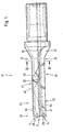
- FIG. 1 shows a drilling tool 11 according to the invention, on the end face thereof 12 two indexable inserts 13, 14 are arranged at an angle of 172 ° are offset from each other.
- the hexagonal indexable inserts 13, 14 have two cutting edges 16, 17; 18, 19 on that at a roof angle are arranged to each other.
- a radially outer insert 14 determines the drilling diameter.
- a radially inner indexable insert 13 is arranged in such a way that their radially inner cutting edge 16 slightly over a drill axis or Longitudinal shaft axis 20 protrudes.
- the indexable inserts 13, 14 have an overlapping one Workspace.
- a recess 22 for chip removal is assigned to the outer indexable insert 14, which is referred to below as the outside span area.
- the outer chip space 22 extends along the longitudinal axis 20 of the shaft over the entire drill shaft 26 and turns into an outlet 27.
- a recess 21 is also assigned to the inner indexable insert 13 hereinafter referred to as the interior chip space.
- the inner chip space 21 has one the indexable insert 13 receiving boundary wall 53 and a substantially Side surface 43 arranged at right angles thereto. In the course of one front area 31 seen in the rear area 32 of the drill shaft 26 this a thread-like pitch.
- the interior chip space passes in a transition region 33 21 in the outside chip space 22, whereby the chip removal in the rear Area 32 of the drill shaft 26 takes place via a common chip space 23.
- the Common chip space 23 is advantageously the continuation of the external chip space 22.
- both the inner chip space 21 and the outer chip space 22 have a helix angle and into a common chip space 23 pass over, which can also be made larger in cross section.
- the common one Chip space 23 can be both straight to the longitudinal axis 20 of the drill and be transferred at a helix angle to the chip outlet 27.
- the inner chip space 21 has an overlap 36, which is at least partially extends over the length of the inner chip space 21 seen in the longitudinal axis direction. advantageously, the overlap 36 extends into the transition region 33, so that the resulting chip on the inner insert 13 within a channel-like trained chip space 21 is guided. Because of the interior chip room 21 arranged cover 36, a closed system has been created.
- the interior chip space has a right-hand twist with an angle in the range of 20 ° to 40 ° on, so that in the closed system a promotional effect for chip evacuation given is.
- the overlap 36 also has the advantage that the chips running off are not pressed against the bore wall, but are discharged in this channel can be avoided, whereby further reaction forces on the drill shaft 26 are avoided are and the drilling tool 11 can thus run much smoother.
- This coverage 36 advantageously represents a measure to calm the vibration or avoidance of vibrations or their excitation is provided.
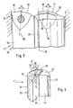
- FIG. 2 shows an end view of the drilling tool 11 according to the invention.
- the overlap 36 arranged on the inner chip space 21 flows smoothly into the lateral surface 34 of the drill shaft 26 over.
- the wall thickness of the cover 36 has in the 5 x D drilling tool according to the invention a wall thickness in one area between 0.5 mm and 4 mm, preferably a wall thickness in the thinnest area is not less than 1 mm. Because of the overlap 36 can be a significant one Stiffening of the basic drill body in the front area, in the case of the invention Drilling tool an angle ⁇ of 172 ° can be achieved. Thereby is the section modulus of the two quarter circle cross sections 37, 38 by essential increases.
- a deviation of the arranged at a certain angle to each other Cutting arrangement can thus be largely prevented, whereby again a reduction in vibration and at the same time an increase in cutting force can be achieved. This is also due to the fact that the small in the interior chip space 21 lying moment of inertia is increased.
- the angular arrangement of 172 ° has the further advantage that the inner chip space 21 is opened or enlarged, whereby a favored chip flow on the inner Enables indexable insert and vibration stabilization is given.
- a coolant bore 39 in a radial inner indexable insert 13 receiving quarter circle cross section is predominant due to the slope of the inner chip space 21, which in the outer chip space 22nd passes, not made possible.
- the interior chip space 21 advantageously goes into the middle to rear area Outer chip space 22 over, so that the rear region 32 of the drill shaft 26 approximately can have a third ⁇ 20% of the total length of the drill shaft 26.
- the cover 36 can cover the inner chip space 21 to such an extent that the transition area 33 exclusively in the plane of a side surface 41 of the Outer chip space 22 is located which receives the radially outer indexable insert 14 Boundary wall 54 is arranged opposite.
- the end face 42 of the cover 36 lies in the side surface 41, to this Side surface 41 is arranged set back, so that the inner chip space 21 only partially is covered.
- end face 42 compared to that previously described axially extending side surface 41 extends radially, so that also the inner chip space 21 is only partially covered and a larger transition area 33 is created can be.
- Fig. 3 is a schematic cross section of the drilling tool 11 along the line III-III shown in Fig. 1. In this area the cross section is approximate Three-quarter full cross section of the drill shaft 26 is formed.
- the common chip space 23 directly adjoins the outer chip space 22 and essentially has the same chip flow volume.
- This side surface 41 and boundary wall 54 are arranged approximately at right angles to one another and form a chip space, which is essentially the first quadrant of the XY-axis coordinate system corresponds.
- At the outer edge zones 56 of the side surface 41 and the boundary wall 54 are each provided with a stiffening bead 57, 58.
- the stiffening bead 57 which is assigned to the side surface 41, extends extends over the entire length of the drill shaft 26 and thereby enables an increase the section modulus as well as the moment of inertia.
- the stiffening bead 57 is formed continuously along the drill shaft 26, provided that one end face 42 of the overlap 36 lies in the side surface 41. If this is not the case, you can the stiffening bead 57 extend into the transition area 33.
- the stiffening bead 58 which is provided on the boundary wall 54, can advantageously up to the front area 31 of the indexable insert 14 extend. It can also be provided that this stiffening bead 58 in the transition area 33 ends.
- the stiffening bead 57, 58 is formed in a strip shape and has a slight increase over the side surfaces 41, 54. In the transition area from the side surface 41 and the boundary wall 54 to the stiffening beads 57, 58 a smooth transition is created.
- the outer edge region 56 of the Stiffening bead 57, 58 directly adjoins a lateral surface 34 of the drill shank 26 and can thereby form a further guide surface.
- the increase the stiffening bead 57, 58 opposite the side surface 41, 54 can be in the range of a few millimeters.
- the width of the stiffening bead 57, 58 is opposite to that Side surface 41, 54 formed small, so that the chip space 23 essentially in size remains completely intact. It also adds to an essential Amount increases the moment of inertia and resistance.
- the indexable inserts 131 14 can be implemented with a clamping bolt exchangeably attached
- the indexable inserts 13, 14 are each with two Cutting edges 16, 17; 18, 19 in the cutting engagement, the indexable insert 13 a adjacent to the longitudinal axis 20 of the drill and overlapping it to a small extent Area intersects and the insert 14 the area of the bore cuts that reaches the circumference of the drill.
- the individual work areas of Indexable inserts 13, 14 overlap in their work areas.
- the indexable inserts 13, 14 each have their cutting edges 16, 17 and 18, 19 an angle bisector 28, 29 which, in relation to a longitudinal axis 20 of a shaft Range between 0 ° and 10 °, preferably around 4 °, with respect to the longitudinal axis of the drill 20 is twisted together.
- This can in connection with the insert arrangement from an angle ⁇ in the range from 165 ° to 185 °, preferably from 172 °, can be achieved that the sum of the effective engaged from all Cutting edges 16, 17; 18, 19 resulting radial force components different from zero is. It can thereby be achieved that the drill 11 during the drilling process with a slightly larger diameter when drilling. This creates the advantage that the drilling tool can not jam in the hole and when When pulling out the drill shaft, there are no retraction marks in the bore wall can.
- the starting material for the production of a drilling tool 11 is a round rod, which is made of known and suitable material for the drilling tool 11. This Round rod is centered in the middle and then one axially over the drill shaft 26 milled outer clamping groove 22, which forms the outer chip space and ends in the outlet 27.
- the inner chip space 21 is milled in, the one in the front region 31 initially essentially at 180 ° to the outer chip space 22 offset inner chip space 21 with a substantially constant Slope is milled, so that it advantageously in a transition area in the central region of the drill shaft 26 merges into the outer chip space 22 and one good promotional effect for chip removal can be achieved. It can be advantageous be provided that the inner chip space 21 from the end face 12 of the drilling tool 11 first seen a straight line before this due to the slope changes into an inclined surface.
- a diameter area is turned off, to which a sleeve, which serves to form the cover 36, is applied.
- the turned diameter range extends along the longitudinal axis 20 towards the rear area 32 of the drill shaft 26.
- the sleeve is turned on the Diameter range applied positively and / or non-positively. This can by known methods such as welding, shrinking, soldering or the like respectively.
- the round bar now becomes off-center to the previous step for the next step clamped so that the round rod is eccentric to its longitudinal axis of the the first operation is recorded by the processing machine.
- the eccentric The round bar taken up in a lathe is now completely turned, so that a common lateral surface 34 of the drilling tool 11 is formed, the extends over the entire length of the drill shaft 26.
- the chip space 22 will thus exposed (by breaking through the sleeve), the chip space 21 still is covered by the sleeve.
- a drill can be created in a small number of manufacturing steps who have high rigidity and low vibration excitation, the is also inexpensive to manufacture.
Landscapes
- Engineering & Computer Science (AREA)
- Mechanical Engineering (AREA)
- Drilling Tools (AREA)
- Processing Of Stones Or Stones Resemblance Materials (AREA)
- Surgical Instruments (AREA)
- Saccharide Compounds (AREA)
- Steroid Compounds (AREA)
Claims (20)
- Outil de perçage pour alésages dans un matériau en métal massif, comprenant une tige (26), avec au moins deux plaquettes de coupe amovibles (13, 14) au moins géométriquement similaires, disposées à une distance radiale différente l'une de l'autre sur la face frontale (12) de la tige (26), dont les zones de travail se recouvrent et dont chacune présente deux arêtes de coupe de même longueur (16, 17, 18, 19), qui sont voisines et inclinées l'une par rapport à l'autre suivant un angle obtus, et qui sont simultanément en engagement, la plaquette de coupe amovible radialement interne (13) dépassant légèrement de l'axe de l'outil 1 de perçage (20) avec l'une de ses arêtes de coupe (16) en prise, la plaquette de coupe amovible radialement extérieure formant le diamètre de perçage avec l'une de ses arêtes de coupe (18) en prise, au moins l'une des bissectrices (28, 29) des arêtes de coupe (16, 17, 18, 19) d'une plaquette de coupe amovible (13, 14) étant inclinée vers l'axe longitudinal de l'outil de perçage (20) suivant un angle (α), avec à chaque fois un logement (21, 22) associé à l'une des plaquettes de coupe amovibles (13, 14), adjacent à une surface d'enveloppe (34) de la tige (26) et avec au moins un logement (21, 22), qui s'étend en position adjacente à la surface d'enveloppe (34) sur toute la tige (26) jusqu'à la sortie (27), caractérisé en ce qu'au moins un logement (21, 22) présente un recouvrement (36) qui s'étend au moins partiellement sur la longueur du logement (21, 22).
- Outil de perçage selon la revendication 1, caractérisé en ce que le recouvrement (36) recouvre un logement (21) associé à la plaquette de coupe amovible radialement interne (13).
- Outil de perçage selon la revendication 1, caractérisé en ce que le logement (22) associé à la plaquette de coupe amovible radialement externe (14) et le logement (21) associé à la plaquette de coupe radialement interne (13) se prolongent en un logement commun (23).
- Outil de perçage selon la revendication 3, caractérisé en ce que le logement commun (23) est la prolongation du logement (22) associé à la plaquette de coupe amovible radialement externe (14).
- Outil de perçage selon l'une quelconque des revendications précédentes, caractérisé en ce que le recouvrement (36) s'étend dans l'axe longitudinal de la tige (20) au moins sur un quart de la longueur de la tige (26).
- Outil de perçage selon l'une quelconque des revendications précédentes, caractérisé en ce que le logement (21) présente une inclinaison conduisant dans un logement (22) s'étendant essentiellement axialement par rapport à l'axe longitudinal de la tige (20).
- Outil de perçage selon l'une quelconque des revendications précédentes, caractérisé en ce que le recouvrement (36) présente une épaisseur de paroi de 0,5 mm à 4 mm.
- Outil de perçage selon l'une quelconque des revendications précédentes, caractérisé en ce que le recouvrement (36) s'étend jusque dans une face latérale (41) du logement (22).
- Outil de perçage selon l'une quelconque des revendications précédentes, caractérisé en ce que le recouvrement (36) est réalisé sous forme d'une partie de la tige (26).
- Outil de perçage selon la revendication 1, caractérisé en ce que l'évidement (22) s'étendant axialement présente au moins sur une face latérale (41) en regard de la plaquette de coupe amovible (14) un bourrelet de renfort (57) adjacent à une surface d'enveloppe (34) de la tige (26), s'étendant axialement au moins partiellement sur toute la longueur de l'évidement (22).
- Outil de perçage selon la revendication 10, caractérisé en ce que le bourrelet de renfort (57) s'étend sur toute la longueur de la tige (26).
- Outil de perçage selon la revendication 10, caractérisé en ce que le bourrelet de renfort (57) est mince par rapport à la largeur de la face latérale (41).
- Outil de perçage selon la revendication 10, caractérisé en ce que le bourrelet de renfort (57) augmente le moment d'inertie et/ou le moment résistant de la tige (26).
- Outil de perçage selon la revendication 10, caractérisé en ce qu'une zone périphérique extérieure du bourrelet de renfort (57) forme une partie de la surface d'enveloppe (34) de la tige (26) et est réalisée en tant que surface de guidage.
- Outil de perçage selon la revendication 10, caractérisé en ce que le bourrelet de renfort (57) dépasse de moins de trois millimètres par rapport à la face latérale (41) du logement (22).
- Outil de perçage selon la revendication 10, caractérisé en ce que le bourrelet de renfort (57) s'étend jusqu'à la zone de transition (33).
- Outil de perçage selon la revendication 1, caractérisé en ce que la tige (26) présente au moins deux logements (21, 22) essentiellement diamétralement opposés, dont la paroi de limitation (53, 54) est disposée à angle droit par rapport à ses faces latérales (41, 43) au moins partiellement le long de la tige (26).
- Outil de perçage selon la revendication 17, caractérisé en ce qu'une section de segment de quart de cercle (63) recevant dans la zone avant (31) de la tige (26) la plaquette de coupe amovible radialement externe (14) présente un alésage pour fluide de refroidissement (39).
- Outil de perçage selon la revendication 17, caractérisé en ce que les faces de limitation (53, 54) et les faces latérales (41, 43) sont essentiellement petites.
- Procédé de fabrication d'un outil de perçage selon l'une quelconque des revendications 1 à 19, caractérisé en ce queune barre ronde est centrée au milieu,un logement (22) pour l'évacuation des copeaux, s'étendant depuis la face frontale (12) de l'outil de perçage (11) le long de la tige (26) est fraisé,un logement (21) pour l'évacuation des copeaux, décalé mutuellement d'un angle périphérique essentiellement égal au niveau de la face frontale (12) de l'outil de perçage (11) et s'étendant au moins partiellement le long de la tige (26) est fraisé, les logements (21, 22) se prolongeant dans une zone arrière (32) de la tige (26) en un logement commun (23),une portion s'étendant depuis la face frontale (12) de la tige (26) au moins partiellement le long de la tige (26) est usinée au tour à un diamètre réduit par rapport au diamètre de la tige,sur cette portion de diamètre réduit, on place, par engagement par force et/ou positif, un manchon,la barre ronde est ensuite serrée de manière excentrique,le manchon et la tige (26) sont usinés au tour à une surface d'enveloppe commune (36) de la tige (26).
Applications Claiming Priority (2)
| Application Number | Priority Date | Filing Date | Title |
|---|---|---|---|
| DE19522836 | 1995-06-23 | ||
| DE19522836A DE19522836A1 (de) | 1995-06-23 | 1995-06-23 | Bohrwerkzeug |
Publications (2)
| Publication Number | Publication Date |
|---|---|
| EP0749795A1 EP0749795A1 (fr) | 1996-12-27 |
| EP0749795B1 true EP0749795B1 (fr) | 2003-01-08 |
Family
ID=7765087
Family Applications (1)
| Application Number | Title | Priority Date | Filing Date |
|---|---|---|---|
| EP96109375A Expired - Lifetime EP0749795B1 (fr) | 1995-06-23 | 1996-06-12 | Outil de perçage |
Country Status (6)
| Country | Link |
|---|---|
| US (1) | US5782587A (fr) |
| EP (1) | EP0749795B1 (fr) |
| KR (1) | KR970000409A (fr) |
| CN (1) | CN1065795C (fr) |
| AT (1) | ATE230646T1 (fr) |
| DE (2) | DE19522836A1 (fr) |
Families Citing this family (17)
| Publication number | Priority date | Publication date | Assignee | Title |
|---|---|---|---|---|
| JP3164479B2 (ja) * | 1994-11-01 | 2001-05-08 | 兼房株式会社 | 回転穿孔工具 |
| DE10021879A1 (de) * | 2000-05-05 | 2001-11-08 | Komet Stahlhalter Werkzeuge | Vollbohrer für Werkzeugmaschinen |
| US7004691B2 (en) * | 2002-11-15 | 2006-02-28 | Unitac Incorporated | Deep hole cutter |
| KR100556681B1 (ko) * | 2003-04-28 | 2006-03-07 | 대구텍 주식회사 | 다기능 절삭 가공용 툴홀더 조립체 |
| DE102006027552B4 (de) * | 2006-06-14 | 2011-06-01 | Audi Ag | Bohrwerkzeug insbesondere für metallische Werkstoffe |
| DE102006049088A1 (de) * | 2006-10-13 | 2008-04-24 | Kennametal Inc. | Modulares Bohrwerkzeug und Verfahren zu seiner Herstellung |
| DE102007042280A1 (de) * | 2007-09-06 | 2009-03-12 | Komet Group Holding Gmbh | Bohrwerkzeug für Werkzeugmaschinen sowie Verfahren zu dessen Herstellung |
| KR101106526B1 (ko) * | 2009-12-10 | 2012-01-20 | 큰산기술 주식회사 | 체크밸브를 갖는 지하수공의 오염방지장치 |
| CN102233441B (zh) * | 2011-04-13 | 2013-01-23 | 中北大学 | 一种基于喷吸机理的连续自动内排屑深孔内扩孔刀具 |
| CN104308232B (zh) * | 2014-09-18 | 2016-10-05 | 宁波市荣科迈特数控刀具有限公司 | 一种多功能钻杆 |
| DE102016113816A1 (de) * | 2016-07-27 | 2018-02-01 | Komet Group Gmbh | Zerspanungswerkzeug |
| CN106625870B (zh) * | 2017-02-20 | 2018-07-10 | 延锋彼欧汽车外饰系统有限公司 | 一种钻孔刀具 |
| EP3401043B1 (fr) * | 2017-05-11 | 2020-03-25 | Sandvik Intellectual Property AB | Corps de trépan et trépan |
| EP3556496A1 (fr) * | 2018-04-17 | 2019-10-23 | Walter Ag | Outil de forage |
| DE102018114139A1 (de) * | 2018-06-13 | 2019-12-19 | Botek Präzisionsbohrtechnik Gmbh | Tieflochbohrer und Bohrwerkzeug mit einer oder mehreren Mulden in der Spanfläche |
| CN109158664B (zh) * | 2018-08-14 | 2021-06-18 | 株洲钻石切削刀具股份有限公司 | 一种可转位钻孔刀具 |
| CN110666890B (zh) * | 2019-09-25 | 2021-05-18 | 绍兴兴裕门窗有限公司 | 一种木质家具加工用木条钻孔设备 |
Family Cites Families (14)
| Publication number | Priority date | Publication date | Assignee | Title |
|---|---|---|---|---|
| US1104989A (en) * | 1914-01-15 | 1914-07-28 | Pratt & Whitney Co | Drill. |
| SU562389A1 (ru) * | 1975-04-08 | 1977-06-25 | Специальное Проектно-Конструкторское Бюро Объединения "Ленмебель" | Спиральное сверло |
| SE411310B (sv) * | 1976-11-17 | 1979-12-17 | Sandvik Ab | Borr, foretredesvis med vendsker |
| SU677826A1 (ru) * | 1977-06-30 | 1979-08-05 | Предприятие П/Я А-3282 | Сверло дл глубокого сверлени |
| DE2903814C2 (de) * | 1979-02-01 | 1982-08-19 | Mapal Fabrik für Präzisionswerkzeuge Dr.Kress KG, 7080 Aalen | Bohrkopf |
| US4340327A (en) * | 1980-07-01 | 1982-07-20 | Gulf & Western Manufacturing Co. | Tool support and drilling tool |
| AT384977B (de) * | 1980-12-22 | 1988-02-10 | Plansee Metallwerk | Bohrwerkzeug |
| CN2046414U (zh) * | 1989-03-24 | 1989-10-25 | 深圳南南电器设备有限公司 | 不锈钢深孔钻头 |
| US4966503A (en) * | 1989-05-30 | 1990-10-30 | The Boeing Company | Drill bit for drilling a hole in layered material of different hardness |
| CN1020075C (zh) * | 1989-09-09 | 1993-03-17 | 西安石油学院 | 一种非对称布置外排屑槽的深孔钻 |
| JPH03142118A (ja) * | 1989-10-27 | 1991-06-17 | Mitsubishi Materials Corp | 穴明け工具 |
| DE4018043A1 (de) * | 1990-06-06 | 1991-12-12 | Krupp Widia Gmbh | Bohrwerkzeug |
| SE504315C2 (sv) * | 1994-05-09 | 1997-01-13 | Sandvik Ab | Borr för metallborrning |
| ATE165033T1 (de) * | 1994-12-10 | 1998-05-15 | Kennametal Hertel Ag | Bohrwerkzeug für bohrungen in metallvollmaterial |
-
1995
- 1995-06-23 DE DE19522836A patent/DE19522836A1/de not_active Ceased
-
1996
- 1996-06-12 AT AT96109375T patent/ATE230646T1/de not_active IP Right Cessation
- 1996-06-12 EP EP96109375A patent/EP0749795B1/fr not_active Expired - Lifetime
- 1996-06-12 DE DE59610035T patent/DE59610035D1/de not_active Expired - Fee Related
- 1996-06-18 CN CN96106350A patent/CN1065795C/zh not_active Expired - Fee Related
- 1996-06-21 KR KR1019960022957A patent/KR970000409A/ko active IP Right Grant
- 1996-06-21 US US08/667,547 patent/US5782587A/en not_active Expired - Fee Related
Also Published As
| Publication number | Publication date |
|---|---|
| DE59610035D1 (de) | 2003-02-13 |
| DE19522836A1 (de) | 1997-01-02 |
| US5782587A (en) | 1998-07-21 |
| EP0749795A1 (fr) | 1996-12-27 |
| CN1065795C (zh) | 2001-05-16 |
| CN1142997A (zh) | 1997-02-19 |
| ATE230646T1 (de) | 2003-01-15 |
| KR970000409A (ko) | 1997-01-21 |
Similar Documents
| Publication | Publication Date | Title |
|---|---|---|
| EP0749795B1 (fr) | Outil de perçage | |
| EP0750960B1 (fr) | Foret, en particulier pour matériaux métalliques | |
| DE3037097C2 (de) | Vollbohrwerkzeug, insbesondere Spiralbohrer | |
| EP1184116B1 (fr) | Outil de fraisage et de perçage | |
| DE69930449T2 (de) | Drehendes Schneidwerkzeug mit Wendeschneideinsatz | |
| EP0597871B1 (fr) | Plaquettes de coupe et outil de per age pour le per age de materiau plein | |
| EP2237913B9 (fr) | Outil de perçage et pointe correspondante | |
| DE69909856T2 (de) | Schaftfräser und Schneidmethode | |
| EP0532532B1 (fr) | Outil de perçage | |
| EP0749794B1 (fr) | Outil de perçage | |
| DE2733705A1 (de) | Bohrwerkzeug mit schneideinsatz | |
| DE4236823A1 (de) | Polierbohrer | |
| EP0146030A2 (fr) | Outil de coupe pour l'usinage de métal par enlèvement de copeaux | |
| WO1991006387A1 (fr) | Foret helicoidal | |
| DE3704106A1 (de) | Bohrwerkzeug zur bearbeitung von langspanenden werkstoffen | |
| EP0334002A2 (fr) | Fraise de filetage | |
| DE3800489C2 (de) | Gewinde-Strehlwerkzeug | |
| EP2076345A1 (fr) | Outil de perçage modulaire et son procédé de fabrication | |
| DE3604390C2 (fr) | ||
| DE4237618A1 (de) | Befestigungsanordnung für einen Werkzeughalter auf einer Werkzeugmaschine | |
| EP0798063B1 (fr) | Outil à aléser | |
| EP1536905B1 (fr) | Outil a percer presentant des matrices de decoupage alternatif, et matrices de decoupage alternatif destinees a un outil a percer de ce type | |
| DE19983133B4 (de) | Reibahle, Reibahlenanordnung und Verfahren zum Fertigbearbeiten einer Anzahl von Öffnungen | |
| EP0264642B1 (fr) | Outil de coupe pour l'usinage de métaux par enlèvement de copeaux en particulier outil de rainurage | |
| DE10144514A1 (de) | Schneidwerkzeug |
Legal Events
| Date | Code | Title | Description |
|---|---|---|---|
| PUAI | Public reference made under article 153(3) epc to a published international application that has entered the european phase |
Free format text: ORIGINAL CODE: 0009012 |
|
| AK | Designated contracting states |
Kind code of ref document: A1 Designated state(s): AT BE CH DE ES FR GB LI NL SE |
|
| RIN1 | Information on inventor provided before grant (corrected) |
Inventor name: BASTECK, ANDREAS, DR. |
|
| 17P | Request for examination filed |
Effective date: 19970613 |
|
| 17Q | First examination report despatched |
Effective date: 19991013 |
|
| GRAG | Despatch of communication of intention to grant |
Free format text: ORIGINAL CODE: EPIDOS AGRA |
|
| GRAG | Despatch of communication of intention to grant |
Free format text: ORIGINAL CODE: EPIDOS AGRA |
|
| GRAH | Despatch of communication of intention to grant a patent |
Free format text: ORIGINAL CODE: EPIDOS IGRA |
|
| GRAH | Despatch of communication of intention to grant a patent |
Free format text: ORIGINAL CODE: EPIDOS IGRA |
|
| GRAA | (expected) grant |
Free format text: ORIGINAL CODE: 0009210 |
|
| AK | Designated contracting states |
Kind code of ref document: B1 Designated state(s): AT BE CH DE ES FR GB LI NL SE |
|
| PG25 | Lapsed in a contracting state [announced via postgrant information from national office to epo] |
Ref country code: FR Free format text: LAPSE BECAUSE OF FAILURE TO SUBMIT A TRANSLATION OF THE DESCRIPTION OR TO PAY THE FEE WITHIN THE PRESCRIBED TIME-LIMIT Effective date: 20030108 |
|
| REF | Corresponds to: |
Ref document number: 230646 Country of ref document: AT Date of ref document: 20030115 Kind code of ref document: T |
|
| REG | Reference to a national code |
Ref country code: GB Ref legal event code: FG4D Free format text: NOT ENGLISH |
|
| REG | Reference to a national code |
Ref country code: CH Ref legal event code: EP |
|
| REF | Corresponds to: |
Ref document number: 59610035 Country of ref document: DE Date of ref document: 20030213 Kind code of ref document: P |
|
| PG25 | Lapsed in a contracting state [announced via postgrant information from national office to epo] |
Ref country code: SE Free format text: LAPSE BECAUSE OF FAILURE TO SUBMIT A TRANSLATION OF THE DESCRIPTION OR TO PAY THE FEE WITHIN THE PRESCRIBED TIME-LIMIT Effective date: 20030408 |
|
| GBT | Gb: translation of ep patent filed (gb section 77(6)(a)/1977) |
Effective date: 20030513 |
|
| REG | Reference to a national code |
Ref country code: CH Ref legal event code: NV Representative=s name: DR. LUSUARDI AG |
|
| PG25 | Lapsed in a contracting state [announced via postgrant information from national office to epo] |
Ref country code: ES Free format text: LAPSE BECAUSE OF FAILURE TO SUBMIT A TRANSLATION OF THE DESCRIPTION OR TO PAY THE FEE WITHIN THE PRESCRIBED TIME-LIMIT Effective date: 20030730 |
|
| PLBE | No opposition filed within time limit |
Free format text: ORIGINAL CODE: 0009261 |
|
| STAA | Information on the status of an ep patent application or granted ep patent |
Free format text: STATUS: NO OPPOSITION FILED WITHIN TIME LIMIT |
|
| EN | Fr: translation not filed | ||
| 26N | No opposition filed |
Effective date: 20031009 |
|
| PGFP | Annual fee paid to national office [announced via postgrant information from national office to epo] |
Ref country code: BE Payment date: 20040409 Year of fee payment: 9 |
|
| PGFP | Annual fee paid to national office [announced via postgrant information from national office to epo] |
Ref country code: AT Payment date: 20040614 Year of fee payment: 9 |
|
| PGFP | Annual fee paid to national office [announced via postgrant information from national office to epo] |
Ref country code: CH Payment date: 20040628 Year of fee payment: 9 |
|
| PGFP | Annual fee paid to national office [announced via postgrant information from national office to epo] |
Ref country code: NL Payment date: 20040629 Year of fee payment: 9 Ref country code: GB Payment date: 20040629 Year of fee payment: 9 |
|
| PGFP | Annual fee paid to national office [announced via postgrant information from national office to epo] |
Ref country code: DE Payment date: 20040901 Year of fee payment: 9 |
|
| PG25 | Lapsed in a contracting state [announced via postgrant information from national office to epo] |
Ref country code: GB Free format text: LAPSE BECAUSE OF NON-PAYMENT OF DUE FEES Effective date: 20050612 Ref country code: AT Free format text: LAPSE BECAUSE OF NON-PAYMENT OF DUE FEES Effective date: 20050612 |
|
| PG25 | Lapsed in a contracting state [announced via postgrant information from national office to epo] |
Ref country code: LI Free format text: LAPSE BECAUSE OF NON-PAYMENT OF DUE FEES Effective date: 20050630 Ref country code: CH Free format text: LAPSE BECAUSE OF NON-PAYMENT OF DUE FEES Effective date: 20050630 Ref country code: BE Free format text: LAPSE BECAUSE OF NON-PAYMENT OF DUE FEES Effective date: 20050630 |
|
| PG25 | Lapsed in a contracting state [announced via postgrant information from national office to epo] |
Ref country code: NL Free format text: LAPSE BECAUSE OF NON-PAYMENT OF DUE FEES Effective date: 20060101 |
|
| PG25 | Lapsed in a contracting state [announced via postgrant information from national office to epo] |
Ref country code: DE Free format text: LAPSE BECAUSE OF NON-PAYMENT OF DUE FEES Effective date: 20060103 |
|
| REG | Reference to a national code |
Ref country code: HK Ref legal event code: WD Ref document number: 1012601 Country of ref document: HK |
|
| REG | Reference to a national code |
Ref country code: CH Ref legal event code: PL |
|
| GBPC | Gb: european patent ceased through non-payment of renewal fee |
Effective date: 20050612 |
|
| NLV4 | Nl: lapsed or anulled due to non-payment of the annual fee |
Effective date: 20060101 |
|
| BERE | Be: lapsed |
Owner name: AUGUST *BECK G.M.B.H. & CO. Effective date: 20050630 |