EP0749795B1 - Drilling tool - Google Patents
Drilling tool Download PDFInfo
- Publication number
- EP0749795B1 EP0749795B1 EP96109375A EP96109375A EP0749795B1 EP 0749795 B1 EP0749795 B1 EP 0749795B1 EP 96109375 A EP96109375 A EP 96109375A EP 96109375 A EP96109375 A EP 96109375A EP 0749795 B1 EP0749795 B1 EP 0749795B1
- Authority
- EP
- European Patent Office
- Prior art keywords
- drilling tool
- recess
- tool according
- drill shank
- drill
- Prior art date
- Legal status (The legal status is an assumption and is not a legal conclusion. Google has not performed a legal analysis and makes no representation as to the accuracy of the status listed.)
- Expired - Lifetime
Links
Images


Classifications
-
- B—PERFORMING OPERATIONS; TRANSPORTING
- B23—MACHINE TOOLS; METAL-WORKING NOT OTHERWISE PROVIDED FOR
- B23B—TURNING; BORING
- B23B51/00—Tools for drilling machines
- B23B51/02—Twist drills
-
- B—PERFORMING OPERATIONS; TRANSPORTING
- B23—MACHINE TOOLS; METAL-WORKING NOT OTHERWISE PROVIDED FOR
- B23B—TURNING; BORING
- B23B51/00—Tools for drilling machines
-
- B—PERFORMING OPERATIONS; TRANSPORTING
- B23—MACHINE TOOLS; METAL-WORKING NOT OTHERWISE PROVIDED FOR
- B23B—TURNING; BORING
- B23B2200/00—Details of cutting inserts
- B23B2200/04—Overall shape
- B23B2200/0404—Hexagonal
- B23B2200/0419—Hexagonal trigonal
-
- B—PERFORMING OPERATIONS; TRANSPORTING
- B23—MACHINE TOOLS; METAL-WORKING NOT OTHERWISE PROVIDED FOR
- B23B—TURNING; BORING
- B23B2251/00—Details of tools for drilling machines
- B23B2251/04—Angles, e.g. cutting angles
-
- B—PERFORMING OPERATIONS; TRANSPORTING
- B23—MACHINE TOOLS; METAL-WORKING NOT OTHERWISE PROVIDED FOR
- B23B—TURNING; BORING
- B23B2251/00—Details of tools for drilling machines
- B23B2251/40—Flutes, i.e. chip conveying grooves
- B23B2251/406—Flutes, i.e. chip conveying grooves of special form not otherwise provided for
-
- B—PERFORMING OPERATIONS; TRANSPORTING
- B23—MACHINE TOOLS; METAL-WORKING NOT OTHERWISE PROVIDED FOR
- B23B—TURNING; BORING
- B23B2251/00—Details of tools for drilling machines
- B23B2251/50—Drilling tools comprising cutting inserts
-
- Y—GENERAL TAGGING OF NEW TECHNOLOGICAL DEVELOPMENTS; GENERAL TAGGING OF CROSS-SECTIONAL TECHNOLOGIES SPANNING OVER SEVERAL SECTIONS OF THE IPC; TECHNICAL SUBJECTS COVERED BY FORMER USPC CROSS-REFERENCE ART COLLECTIONS [XRACs] AND DIGESTS
- Y10—TECHNICAL SUBJECTS COVERED BY FORMER USPC
- Y10S—TECHNICAL SUBJECTS COVERED BY FORMER USPC CROSS-REFERENCE ART COLLECTIONS [XRACs] AND DIGESTS
- Y10S408/00—Cutting by use of rotating axially moving tool
- Y10S408/713—Tool having detachable cutting edge
-
- Y—GENERAL TAGGING OF NEW TECHNOLOGICAL DEVELOPMENTS; GENERAL TAGGING OF CROSS-SECTIONAL TECHNOLOGIES SPANNING OVER SEVERAL SECTIONS OF THE IPC; TECHNICAL SUBJECTS COVERED BY FORMER USPC CROSS-REFERENCE ART COLLECTIONS [XRACs] AND DIGESTS
- Y10—TECHNICAL SUBJECTS COVERED BY FORMER USPC
- Y10T—TECHNICAL SUBJECTS COVERED BY FORMER US CLASSIFICATION
- Y10T408/00—Cutting by use of rotating axially moving tool
- Y10T408/44—Cutting by use of rotating axially moving tool with means to apply transient, fluent medium to work or product
- Y10T408/45—Cutting by use of rotating axially moving tool with means to apply transient, fluent medium to work or product including Tool with duct
- Y10T408/455—Conducting channel extending to end of Tool
-
- Y—GENERAL TAGGING OF NEW TECHNOLOGICAL DEVELOPMENTS; GENERAL TAGGING OF CROSS-SECTIONAL TECHNOLOGIES SPANNING OVER SEVERAL SECTIONS OF THE IPC; TECHNICAL SUBJECTS COVERED BY FORMER USPC CROSS-REFERENCE ART COLLECTIONS [XRACs] AND DIGESTS
- Y10—TECHNICAL SUBJECTS COVERED BY FORMER USPC
- Y10T—TECHNICAL SUBJECTS COVERED BY FORMER US CLASSIFICATION
- Y10T408/00—Cutting by use of rotating axially moving tool
- Y10T408/55—Cutting by use of rotating axially moving tool with work-engaging structure other than Tool or tool-support
- Y10T408/557—Frictionally engaging sides of opening in work
- Y10T408/558—Opening coaxial with Tool
- Y10T408/5583—Engaging sides of opening being enlarged by Tool
- Y10T408/5586—Engaging surface subsequent to tool-action on that surface
-
- Y—GENERAL TAGGING OF NEW TECHNOLOGICAL DEVELOPMENTS; GENERAL TAGGING OF CROSS-SECTIONAL TECHNOLOGIES SPANNING OVER SEVERAL SECTIONS OF THE IPC; TECHNICAL SUBJECTS COVERED BY FORMER USPC CROSS-REFERENCE ART COLLECTIONS [XRACs] AND DIGESTS
- Y10—TECHNICAL SUBJECTS COVERED BY FORMER USPC
- Y10T—TECHNICAL SUBJECTS COVERED BY FORMER US CLASSIFICATION
- Y10T408/00—Cutting by use of rotating axially moving tool
- Y10T408/89—Tool or Tool with support
- Y10T408/909—Having peripherally spaced cutting edges
- Y10T408/9095—Having peripherally spaced cutting edges with axially extending relief channel
- Y10T408/9097—Spiral channel
Definitions
- the invention relates to a drilling tool for drilling in solid metal according to the Preamble of claim 1 and as from EP-A-0054913 is known.
- a drilling tool for drilling in solid metal material is known from EP 0 054 913 A2, the one drill shaft with at least two at the same circumferential angle intervals has offset recordings, in each of which at least one or more Exchangeable indexable inserts with radial cutting edges of the same length Direction is arranged. There is a recess for each of these inserts intended for chip removal, which extends axially into a rear area of the drill shank extends.
- the respective bisector of the engaged one Cutting edges enclose an acute angle with a parallel to the drilling axis. This allows a radial cut compensation to be created so that the drill centered itself and causes material removal along the drilling axis.
- the object of the invention is therefore to create a drilling tool, which increases the rigidity of the drill shank and reduces vibration Process enables the invention is also based on the object specify a method by which such a drilling tool in a simple Wise and inexpensive to manufacture.
- This task is accomplished by a drilling tool according to the characteristic features of claim 1 solved.
- the formation of an overlap from a chip space in the the front area of the drill shank enables a higher rigidity of the drill shank cross section.
- the two are arranged essentially opposite one another Cutting edges of the indexable inserts can thereby be removed during the cutting process essentially in their given by the cross section of the drill shaft Positioning are held. This can minimize vibration excitation be reduced.
- This has the advantage that the cutting force or the cutting engagement can be kept essentially constant over the entire drilling process, whereby the resulting force acting on the cutting edges is also essentially a has constant size. Through this vibration-free drilling process can increase the feed force and thus shorten the drilling time be made possible, at the same time the drilling base and the drilling wall of high Quality level are and in particular the drilling ground is free of chatter marks
- An advantageous embodiment of the invention is that one of the radially inner indexable insert assigned internal chip space in one of the radially outer indexable insert assigned outside span area
- the outside span area extends advantageously along the longitudinal axis of the drill, the inner chip space advantageously has a slope, so that in the front area by substantially Inner chip space arranged at 180 ° to the outer chip space into the outer chip space can pass over. This can be in the rear area of the drill shaft in turn a cross-sectional enlargement can be achieved which is a substantial increase the rigidity of the drilling tool.
- transition area from the inside chip area to the outside chip area in the middle to rear area of the drill shaft can be provided so that a rear region of the drill shaft can be provided with a 3/4 cross-section, which is in relation to the The cross section in the front area of the drill shank is large the common chip space adjoining the transition area essentially corresponds the size of the external chip space and advantageously runs in its size constant over the remaining length of the drill shank.
- Another advantageous embodiment of the drilling tool provides that the Large transition area between the inner chip space and the outer chip space is so that the to be discharged and meet in this area Chips can still be easily removed without causing chips or a ball formation occurs.
- the Bisectors of the equally long cutting edges of the radially inner and outer Inserts together around the longitudinal axis of the drill shank are inclined at a small angle.
- This twist especially in the arrangement of the indexable inserts, seen radially to the longitudinal axis of the drill shank are arranged at about 172 ° offset from each other, an intervention of the Indexable inserts can be selected in which the resulting radial force components are different from zero. This allows holes to be cut whose Diameter is slightly larger than the drill diameter. When pulling out the drilling tool from the borehole cannot pull back occur more.
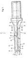
- FIG. 1 shows a drilling tool 11 according to the invention, on the end face thereof 12 two indexable inserts 13, 14 are arranged at an angle of 172 ° are offset from each other.
- the hexagonal indexable inserts 13, 14 have two cutting edges 16, 17; 18, 19 on that at a roof angle are arranged to each other.
- a radially outer insert 14 determines the drilling diameter.
- a radially inner indexable insert 13 is arranged in such a way that their radially inner cutting edge 16 slightly over a drill axis or Longitudinal shaft axis 20 protrudes.
- the indexable inserts 13, 14 have an overlapping one Workspace.
- a recess 22 for chip removal is assigned to the outer indexable insert 14, which is referred to below as the outside span area.
- the outer chip space 22 extends along the longitudinal axis 20 of the shaft over the entire drill shaft 26 and turns into an outlet 27.
- a recess 21 is also assigned to the inner indexable insert 13 hereinafter referred to as the interior chip space.
- the inner chip space 21 has one the indexable insert 13 receiving boundary wall 53 and a substantially Side surface 43 arranged at right angles thereto. In the course of one front area 31 seen in the rear area 32 of the drill shaft 26 this a thread-like pitch.
- the interior chip space passes in a transition region 33 21 in the outside chip space 22, whereby the chip removal in the rear Area 32 of the drill shaft 26 takes place via a common chip space 23.
- the Common chip space 23 is advantageously the continuation of the external chip space 22.
- both the inner chip space 21 and the outer chip space 22 have a helix angle and into a common chip space 23 pass over, which can also be made larger in cross section.
- the common one Chip space 23 can be both straight to the longitudinal axis 20 of the drill and be transferred at a helix angle to the chip outlet 27.
- the inner chip space 21 has an overlap 36, which is at least partially extends over the length of the inner chip space 21 seen in the longitudinal axis direction. advantageously, the overlap 36 extends into the transition region 33, so that the resulting chip on the inner insert 13 within a channel-like trained chip space 21 is guided. Because of the interior chip room 21 arranged cover 36, a closed system has been created.
- the interior chip space has a right-hand twist with an angle in the range of 20 ° to 40 ° on, so that in the closed system a promotional effect for chip evacuation given is.
- the overlap 36 also has the advantage that the chips running off are not pressed against the bore wall, but are discharged in this channel can be avoided, whereby further reaction forces on the drill shaft 26 are avoided are and the drilling tool 11 can thus run much smoother.
- This coverage 36 advantageously represents a measure to calm the vibration or avoidance of vibrations or their excitation is provided.
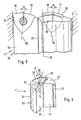
- FIG. 2 shows an end view of the drilling tool 11 according to the invention.
- the overlap 36 arranged on the inner chip space 21 flows smoothly into the lateral surface 34 of the drill shaft 26 over.
- the wall thickness of the cover 36 has in the 5 x D drilling tool according to the invention a wall thickness in one area between 0.5 mm and 4 mm, preferably a wall thickness in the thinnest area is not less than 1 mm. Because of the overlap 36 can be a significant one Stiffening of the basic drill body in the front area, in the case of the invention Drilling tool an angle ⁇ of 172 ° can be achieved. Thereby is the section modulus of the two quarter circle cross sections 37, 38 by essential increases.
- a deviation of the arranged at a certain angle to each other Cutting arrangement can thus be largely prevented, whereby again a reduction in vibration and at the same time an increase in cutting force can be achieved. This is also due to the fact that the small in the interior chip space 21 lying moment of inertia is increased.
- the angular arrangement of 172 ° has the further advantage that the inner chip space 21 is opened or enlarged, whereby a favored chip flow on the inner Enables indexable insert and vibration stabilization is given.
- a coolant bore 39 in a radial inner indexable insert 13 receiving quarter circle cross section is predominant due to the slope of the inner chip space 21, which in the outer chip space 22nd passes, not made possible.
- the interior chip space 21 advantageously goes into the middle to rear area Outer chip space 22 over, so that the rear region 32 of the drill shaft 26 approximately can have a third ⁇ 20% of the total length of the drill shaft 26.
- the cover 36 can cover the inner chip space 21 to such an extent that the transition area 33 exclusively in the plane of a side surface 41 of the Outer chip space 22 is located which receives the radially outer indexable insert 14 Boundary wall 54 is arranged opposite.
- the end face 42 of the cover 36 lies in the side surface 41, to this Side surface 41 is arranged set back, so that the inner chip space 21 only partially is covered.
- end face 42 compared to that previously described axially extending side surface 41 extends radially, so that also the inner chip space 21 is only partially covered and a larger transition area 33 is created can be.
- Fig. 3 is a schematic cross section of the drilling tool 11 along the line III-III shown in Fig. 1. In this area the cross section is approximate Three-quarter full cross section of the drill shaft 26 is formed.
- the common chip space 23 directly adjoins the outer chip space 22 and essentially has the same chip flow volume.
- This side surface 41 and boundary wall 54 are arranged approximately at right angles to one another and form a chip space, which is essentially the first quadrant of the XY-axis coordinate system corresponds.
- At the outer edge zones 56 of the side surface 41 and the boundary wall 54 are each provided with a stiffening bead 57, 58.
- the stiffening bead 57 which is assigned to the side surface 41, extends extends over the entire length of the drill shaft 26 and thereby enables an increase the section modulus as well as the moment of inertia.
- the stiffening bead 57 is formed continuously along the drill shaft 26, provided that one end face 42 of the overlap 36 lies in the side surface 41. If this is not the case, you can the stiffening bead 57 extend into the transition area 33.
- the stiffening bead 58 which is provided on the boundary wall 54, can advantageously up to the front area 31 of the indexable insert 14 extend. It can also be provided that this stiffening bead 58 in the transition area 33 ends.
- the stiffening bead 57, 58 is formed in a strip shape and has a slight increase over the side surfaces 41, 54. In the transition area from the side surface 41 and the boundary wall 54 to the stiffening beads 57, 58 a smooth transition is created.
- the outer edge region 56 of the Stiffening bead 57, 58 directly adjoins a lateral surface 34 of the drill shank 26 and can thereby form a further guide surface.
- the increase the stiffening bead 57, 58 opposite the side surface 41, 54 can be in the range of a few millimeters.
- the width of the stiffening bead 57, 58 is opposite to that Side surface 41, 54 formed small, so that the chip space 23 essentially in size remains completely intact. It also adds to an essential Amount increases the moment of inertia and resistance.
- the indexable inserts 131 14 can be implemented with a clamping bolt exchangeably attached
- the indexable inserts 13, 14 are each with two Cutting edges 16, 17; 18, 19 in the cutting engagement, the indexable insert 13 a adjacent to the longitudinal axis 20 of the drill and overlapping it to a small extent Area intersects and the insert 14 the area of the bore cuts that reaches the circumference of the drill.
- the individual work areas of Indexable inserts 13, 14 overlap in their work areas.
- the indexable inserts 13, 14 each have their cutting edges 16, 17 and 18, 19 an angle bisector 28, 29 which, in relation to a longitudinal axis 20 of a shaft Range between 0 ° and 10 °, preferably around 4 °, with respect to the longitudinal axis of the drill 20 is twisted together.
- This can in connection with the insert arrangement from an angle ⁇ in the range from 165 ° to 185 °, preferably from 172 °, can be achieved that the sum of the effective engaged from all Cutting edges 16, 17; 18, 19 resulting radial force components different from zero is. It can thereby be achieved that the drill 11 during the drilling process with a slightly larger diameter when drilling. This creates the advantage that the drilling tool can not jam in the hole and when When pulling out the drill shaft, there are no retraction marks in the bore wall can.
- the starting material for the production of a drilling tool 11 is a round rod, which is made of known and suitable material for the drilling tool 11. This Round rod is centered in the middle and then one axially over the drill shaft 26 milled outer clamping groove 22, which forms the outer chip space and ends in the outlet 27.
- the inner chip space 21 is milled in, the one in the front region 31 initially essentially at 180 ° to the outer chip space 22 offset inner chip space 21 with a substantially constant Slope is milled, so that it advantageously in a transition area in the central region of the drill shaft 26 merges into the outer chip space 22 and one good promotional effect for chip removal can be achieved. It can be advantageous be provided that the inner chip space 21 from the end face 12 of the drilling tool 11 first seen a straight line before this due to the slope changes into an inclined surface.
- a diameter area is turned off, to which a sleeve, which serves to form the cover 36, is applied.
- the turned diameter range extends along the longitudinal axis 20 towards the rear area 32 of the drill shaft 26.
- the sleeve is turned on the Diameter range applied positively and / or non-positively. This can by known methods such as welding, shrinking, soldering or the like respectively.
- the round bar now becomes off-center to the previous step for the next step clamped so that the round rod is eccentric to its longitudinal axis of the the first operation is recorded by the processing machine.
- the eccentric The round bar taken up in a lathe is now completely turned, so that a common lateral surface 34 of the drilling tool 11 is formed, the extends over the entire length of the drill shaft 26.
- the chip space 22 will thus exposed (by breaking through the sleeve), the chip space 21 still is covered by the sleeve.
- a drill can be created in a small number of manufacturing steps who have high rigidity and low vibration excitation, the is also inexpensive to manufacture.
Landscapes
- Engineering & Computer Science (AREA)
- Mechanical Engineering (AREA)
- Drilling Tools (AREA)
- Processing Of Stones Or Stones Resemblance Materials (AREA)
- Surgical Instruments (AREA)
- Saccharide Compounds (AREA)
- Steroid Compounds (AREA)
Abstract
Description
Die Erfindung betrifft ein Bohrwerkzeug für Bohrungen in Metallvollmaterial gemäß dem Oberbegriff des Patentanspruchs 1 und wie aus der EP-A-0054913 bekannt ist.The invention relates to a drilling tool for drilling in solid metal according to the Preamble of claim 1 and as from EP-A-0054913 is known.
Aus der EP 0 054 913 A2 ist ein Bohrwerkzeug für Bohrungen in Metallvollmaterial bekannt, das einen Bohrerschaft mit mindestens zwei in gleichen Umfangswinkel-Abständen versetzten Aufnahmen aufweist, in die jeweils mindestens eine, mehrere gleich lange Schneidkanten aufweisende, auswechselbare Wendeschneidplatten in radialer Richtung angeordnet ist. Für jede dieser Wendeschneidplatte ist eine Ausnehmung für die Spanabfuhr vorgesehen, die sich axial in einen hinteren Bereich des Bohrerschaftes erstreckt. Die jeweilige Winkelhalbierende der in Eingriff stehenden Schneidkanten schließt mit einer Parallelen zur Bohrachse einen spitzen Winkel ein. Dadurch kann ein radialer Schnittausgleich geschaffen werden, so daß sich der Bohrer selbst zentriert und entlang der Bohrachse einen Materialabtrag bewirkt.A drilling tool for drilling in solid metal material is known from EP 0 054 913 A2, the one drill shaft with at least two at the same circumferential angle intervals has offset recordings, in each of which at least one or more Exchangeable indexable inserts with radial cutting edges of the same length Direction is arranged. There is a recess for each of these inserts intended for chip removal, which extends axially into a rear area of the drill shank extends. The respective bisector of the engaged one Cutting edges enclose an acute angle with a parallel to the drilling axis. This allows a radial cut compensation to be created so that the drill centered itself and causes material removal along the drilling axis.
Derartige Bohrer haben jedoch den Nachteil, daß sie aufgrund ihres Querschnittsprofils über den gesamten Bohrerschaft eine geringe Steifigkeit aufweisen, was zur Folge hat, daß während des Schneidvorganges das Bohrwerkzeug in Schwingungen versetzt wird, wodurch Rattermarken im Bohrgrund entstehen können. Ferner ist damit eine Verminderung der Schnittleistung und Standzeiten verbunden. Aufgrund der Wendeschneicfpiafienanordnung ist zwar ein Ausgleich der radialen Schnittkraft gegeben, jedoch entstehen dadurch beim Herausziehen des Bohrwerkzeuges Rückzugsriefen, die die Qualität der Bohrung beeinflussen.However, such drills have the disadvantage that they are due to their cross-sectional profile have low stiffness over the entire drill shank, which means that the drilling tool vibrates during the cutting process , which can cause chatter marks in the bottom of the drill. It is also a Reduction of cutting performance and downtimes. Because of the indexable cutting arrangement the radial cutting force is compensated, however This creates retraction grooves when pulling out the drilling tool influence the quality of the hole.
Der Erfindung liegt deshalb die Aufgabe zugrunde, ein Bohrwerkzeug zu schaffen, welches die Steifigkeit des Bohrerschaftes erhöht und einen schwingungsberuhigten Vorgang ermöglicht Des weiteren liegt der Erfindung die Aufgabe zugrunde, ein Verfahren anzugeben, durch welches ein derartiges Bohrwerkzeug in einfacher Weise und kostengünstig hergestellt wird.The object of the invention is therefore to create a drilling tool, which increases the rigidity of the drill shank and reduces vibration Process enables the invention is also based on the object specify a method by which such a drilling tool in a simple Wise and inexpensive to manufacture.
Diese Aufgabe wird durch ein Bohrwerkzeug gemäß den kennzeichnenden Merkmalen des Anspruchs 1 gelöst. Die Ausbildung einer Überdeckung von einem Spanraum im vorderen Bereich des Bohrerschaftes ermöglicht eine höhere Steifigkeit des Bohrerschaftquerschnittes. Die beiden im wesentlichen einander gegenüberliegend angeordneten Schneidkanten der Wendeschneidplatten können dadurch während des Schneidvorganges im wesentlichen in ihrer durch den Querschnitt des Bohrschaftes gegebenen Positionierung gehalten werden. Dadurch kann eine Schwingungserregung auf ein Minimum reduziert werden. Dies hat den Vorteil, daß die Schnittkraft bzw. der Schneideingriff im wesentlichen über den gesamten Bohrvorgang konstant gehalten werden kann, wodurch die an den Schneidkanten angreifende resultierende Kraft ebenso eine im wesentlichen konstante Größe aufweist. Durch diesen schwingungsberuhigten Bohrvorgang kann eine Erhöhung der Vorschubkraft und somit eine Verkürzung der Bohrzeit ermöglicht sein, wobei gleichzeitig der Bohrgrund als auch die Bohrwandung von hoher Qualitätsstufe sind und insbesondere der Bohrgrund frei von Rattermarken istThis task is accomplished by a drilling tool according to the characteristic features of claim 1 solved. The formation of an overlap from a chip space in the the front area of the drill shank enables a higher rigidity of the drill shank cross section. The two are arranged essentially opposite one another Cutting edges of the indexable inserts can thereby be removed during the cutting process essentially in their given by the cross section of the drill shaft Positioning are held. This can minimize vibration excitation be reduced. This has the advantage that the cutting force or the cutting engagement can be kept essentially constant over the entire drilling process, whereby the resulting force acting on the cutting edges is also essentially a has constant size. Through this vibration-free drilling process can increase the feed force and thus shorten the drilling time be made possible, at the same time the drilling base and the drilling wall of high Quality level are and in particular the drilling ground is free of chatter marks
Eine vorteilhafte Ausführungsform der Erfindung ist es, daß ein der radial inneren Wendeschneidplatte zugeordneter Innenspanraum in einen der radial äußeren Wendeschneidplatte zugeordneten Außenspanraum übergeht Der Außenspanraum erstreckt sich dabei vorteilhafterweise längs der Bohrerlängsachse, wobei der Innenspanraum vorteilhafterweise eine Steigung aufweist, damit der im vorderen Bereich um im wesentlichen 180° versetzt zu dem Außenspanraum angeordnete Innenspanraum in den Außenspanraum übergehen kann. Dadurch kann im hinteren Bereich des Bohrerschaftes wiederum eine Querschnittsvergrößerung erzielt werden, die eine wesentliche Erhöhung der Steifigkeit des Bohrwerkzeuges ermöglicht. An advantageous embodiment of the invention is that one of the radially inner indexable insert assigned internal chip space in one of the radially outer indexable insert assigned outside span area The outside span area extends advantageously along the longitudinal axis of the drill, the inner chip space advantageously has a slope, so that in the front area by substantially Inner chip space arranged at 180 ° to the outer chip space into the outer chip space can pass over. This can be in the rear area of the drill shaft in turn a cross-sectional enlargement can be achieved which is a substantial increase the rigidity of the drilling tool.
Eine weitere vorteilhafte Ausführungsform der Erfindung sieht vor, daß der Übergangsbereich von den Innenspanraum in den Außenspanraum im mittleren bis hinteren Bereich des Bohrerschaftes vorgesehen sein kann, so daß ein hinterer Bereich des Bohrerschaftes mit einem 3/4-Querschnitt vorgesehen sein kann, der im Verhältnis zu dem Querschnitt im vorderen Bereich des Bohrerschaftes groß ausgebildet ist Der sich an den Übergangsbereich anschließende gemeinsame Spanraum entspricht im wesentlichen der Größe des Außenspanraumes und verläuft vorteilhafterweise in seiner Größe konstant über die Restlänge des Bohrerschaftes.Another advantageous embodiment of the invention provides that the transition area from the inside chip area to the outside chip area in the middle to rear area of the drill shaft can be provided so that a rear region of the drill shaft can be provided with a 3/4 cross-section, which is in relation to the The cross section in the front area of the drill shank is large the common chip space adjoining the transition area essentially corresponds the size of the external chip space and advantageously runs in its size constant over the remaining length of the drill shank.
Eine weitere vorteilhafte Ausführungsform des Bohrwerkzeuges sieht vor, daß der Übergangsbereich zwischen dem Innenspanraum und dem Außenspanraum groß ausgebildet ist, so daß die abzuführenden und in diesem Bereich aufeinandertreffende Späne weiterhin gut abgeführt werden können, ohne daß es zu einem Spänestau oder einer Knäuelbildung kommt. Die dabei auftretenden, auf den Bohrerschaft einwirkenden Kräfte, die durch das Aufeinandertreffen der Späne des Innen- und Außenspanraumes auftreten könnten, werden von dem Bohrerschaft problemlos aufgenommen, der in diesem Bereich bereits aufgrund des 3/4-Querschnitts bzw. nur einem gemeinsamen Spanraum eine hohe Steifigkeit aufweist.Another advantageous embodiment of the drilling tool provides that the Large transition area between the inner chip space and the outer chip space is so that the to be discharged and meet in this area Chips can still be easily removed without causing chips or a ball formation occurs. The occurring, acting on the drill shank Forces caused by the collision of the chips of the inner and outer chip space could occur, are easily taken up by the drill shank, which in this Area already due to the 3/4 cross-section or only a common one Chip space has a high rigidity.
Nach einer weiteren vorteilhaften Ausgestaltung der Erfindung ist vorgesehen, daß die Winkelhalbierenden der gleich langen Schneidkanten der radial inneren und äußeren Wendeschneidplatten gemeinsam gegenüber der Längsachse des Bohrerschaftes um einen geringen Winkel geneigt sind. Durch diese Verdrehung, insbesondere bei der Anordnung der Wendeschneidplatten, die radial zur Längsachse des Bohrerschaftes gesehen um in etwa 172° einander versetzt angeordnet sind, kann bewußt ein Eingriff der Wendeschneidplatten gewählt werden, bei dem die resultierenden Radialkraftkomponenten von Null verschieden sind. Dadurch können Bohrlöcher geschnitten werden, deren Durchmesser geringfügig größer als der Bohrerdurchmesser ist. Beim Herausziehen des Bohrwerkzeuges aus dem Bohrloch können dadurch keine Rückzugsriefen mehr auftreten. According to a further advantageous embodiment of the invention it is provided that the Bisectors of the equally long cutting edges of the radially inner and outer Inserts together around the longitudinal axis of the drill shank are inclined at a small angle. This twist, especially in the arrangement of the indexable inserts, seen radially to the longitudinal axis of the drill shank are arranged at about 172 ° offset from each other, an intervention of the Indexable inserts can be selected in which the resulting radial force components are different from zero. This allows holes to be cut whose Diameter is slightly larger than the drill diameter. When pulling out the drilling tool from the borehole cannot pull back occur more.
In den weiteren Unteransprüchen und der Beschreibung sind weitere vorteilhafte Ausgestaltungen und Weiterbildungen des erfindungsgemäßen Bohrwerkzeuges angegeben.Further advantageous configurations are in the further subclaims and the description and further developments of the drilling tool according to the invention specified.
In den Zeichnungen ist ein bevorzugtes Ausführungsbeispiel dargestellt. Es zeigen:
- Fig. 1
- eine Seitenansicht des erfindungsgemäßen Bohrwerkzeuges,
- Fig. 2
- eine Stimansicht des Bohrwerkzeuges nach Fig. 1,
- Fig. 3
- einen schematischen Querschnitt des Bohrwerkzeuges entlang der Linie III-III in Fig. 1,
- Fig. 4
- eine perspektivische Ansicht auf einen vorderen Bereich des erfindungsgemäßen Bohrwerkzeuges und
- Fig. 5
- eine schematische Darstellung des erfindungsgemäßen Bohrwerkzeuges mit symmetrischer Verdrehung der Wendeschneidplatten.
- Fig. 1
- a side view of the drilling tool according to the invention,
- Fig. 2
- 1 shows an end view of the drilling tool according to FIG. 1,
- Fig. 3
- 2 shows a schematic cross section of the drilling tool along the line III-III in FIG. 1,
- Fig. 4
- a perspective view of a front region of the drilling tool according to the invention and
- Fig. 5
- is a schematic representation of the drilling tool according to the invention with symmetrical rotation of the inserts.
In Fig. 1 ist ein erfindungsgemäßes Bohrwerkzeug 11 dargestellt, an dessen Stirnseite
12 zwei Wendeschneidplatten 13, 14 angeordnet sind, die in einem Winkel von 172°
zueinander versetzt sind. Die sechseckigen Wendeschneidplatten 13, 14 weisen zwei
im wesentlichen gleich lange Schneidkanten 16, 17; 18, 19 auf, die in einem Dachwinkel
zueinander angeordnet sind. Eine radial äußere Wendeschneidplatte 14 bestimmt
den Bohrdurchmesser. Eine radial innere Wendeschneidplatte 13 ist derart angeordnet,
daß deren radial innere Schneidkante 16 geringfügig über eine Bohrerachse bzw.
Schaftlängsachse 20 hinausragt. Die Wendeschneidplatten 13, 14 weisen einen überlappenden
Arbeitsbereich auf.1 shows a
Der äußeren Wendeschneidplatte 14 ist eine Ausnehmung 22 zur Spanabfuhr zugeordnet,
die im folgenden als Außenspanraum bezeichnet wird. Der Außenspanraum 22 erstreckt
sich längs der Schaftlängsachse 20 über den gesamten Bohrerschaft 26 und
geht in einen Auslauf 27 über.A
Der inneren Wendeschneidplatte 13 ist ebenfalls eine Ausnehmung 21 zugeordnet, die
im folgenden als Innenspanraum bezeichnet wird. Der Innenspanraum 21 weist eine
die Wendeschneidplatte 13 aufnehmende Begrenzungswand 53 und eine im wesentlichen
rechtwinklig dazu angeordnete Seitenfläche 43 auf. In seinem Verlauf von einem
vorderen Bereich 31 in den hinteren Bereich 32 des Bohrerschaftes 26 gesehen weist
dieser eine gewindeähnliche Steigung auf. In einem Übergangsbereich 33 geht der Innenspanraum
21 in den Außenspanraum 22 über, wodurch die Spanabfuhr im hinteren
Bereich 32 des Bohrerschaftes 26 über einen gemeinsamen Spanraum 23 erfolgt. Der
gemeinsame Spanraum 23 ist vorteilhafterweise die Fortsetzung des Außenspanraumes
22. Alternativ kann vorgesehen sein, daß sowohl der Innenspanraum 21 als auch
der Außenspanraum 22 einen Drallwinkel aufweisen und in einen gemeinsamen Spanraum
23 übergehen, der im Querschnitt auch größer ausgebildet sein kann. Der gemeinsame
Spanraum 23 kann sowohl geradlinig zu der Bohrerlängsachse 20 als auch
unter einen Drallwinkel zum Spanauslauf 27 übergeführt werden.A
Der Innenspanraum 21 weist eine Überdeckung 36 auf, die sich zumindest teilweise
über die Länge des Innenspanraumes 21 in Achslängsrichtung gesehen erstreckt. Vorteilhafterweise
erstreckt sich die Überdeckung 36 bis in den Übergangsbereich 33, so
daß der an der inneren Wendeschneidplatte 13 anfallende Span innerhalb eines kanalartig
ausgebildeten Spanraumes 21 geführt wird. Aufgrund der zu dem Innenspanraum
21 angeordneten Überdeckung 36 ist ein geschlossenes System geschaffen worden.
Der Innenspanraum weist einen Rechtsdrall mit einem Winkel im Bereich von 20° bis
40° auf, damit in dem geschlossenen System eine Förderwirkung für die Spanabfuhr
gegeben ist.The
Die Überdeckung 36 weist desweiteren den Vorteil auf, daß die ablaufenden Späne
nicht gegen die Bohrungswand gedrückt werden, sondern in diesem Kanal abgeführt
werden können, wodurch weitere Reaktionskräfte auf den Bohrerschaft 26 vermieden
werden und das Bohrwerkzeug 11 somit wesentlich ruhiger laufen kann. Diese Überdeckung
36 stellt vorteilhafterweise eine Maßnahme dar, die zur Schwingungsberuhigung
oder Vermeidung von Schwingungen bzw. deren Erregung vorgesehen ist.The
In Fig. 2 ist eine Stirnansicht des erfindungsgemäßen Bohrwerkzeuges 11 dargestellt.
Die an dem Innenspanraum 21 angeordnete Überdeckung 36 geht fließend in die Mantelfläche
34 des Bohrerschaftes 26 über. Die Wandstärke der Überdeckung 36 weist
bei dem erfindungsgemäßen 5 x D-Bohrwerkzeug eine Wandstärke in einem Bereich
zwischen 0,5 mm und 4 mm auf, wobei vorzugsweise im dünnsten Bereich eine Wandstärke
von 1 mm nicht unterschritten ist. Aufgrund der Überdeckung 36 kann eine wesentliche
Versteifung des Bohrgrundkörpers im vorderen Bereich, die bei dem erfindungsgemäßen
Bohrwerkzeug einen Winkel Ω von 172° beträgt, erreicht werden. Dadurch
ist das Widerstandsmoment der beiden Viertelkreisquerschnitte 37, 38 um ein
wesentliches erhöht. Ein Abweichen der in einem bestimmten Winkel zueinander angeordneten
Schneidenanordnung kann damit weitgehendst unterbunden werden, wodurch
wiederum eine Schwingungsverringerung und gleichzeitig eine Schnittkrafterhöhung
erzielt werden kann. Dies beruht auch darauf, daß das ansich geringe im Innenspanraum
21 liegende Trägheitsmoment erhöht wird.FIG. 2 shows an end view of the
Die Winkelanordnung von 172° hat des weiteren den Vorteil, daß der Innenspanraum
21 geöffnet bzw. vergrößert wird, wodurch ein begünstigter Spanablauf an der inneren
Wendeschneidplatte ermöglicht und eine Schwingungsberuhigung gegeben ist.The angular arrangement of 172 ° has the further advantage that the
Zur Kühlung des Bohrwerkzeuges 11 während des Schneideinsatzes ist eine Kühlflüssigkeitsbohrung
39 in einem die radial äußere Wendeschneidplatte 14 aufnehmenden
Viertelkreisquerschnitt 63 vorgesehen. Eine Kühlflüssigkeitsbohrung 39 in einem die radial
innere Wendeschneidplatte 13 aufnehmenden Viertelkreisquerschnitt wird überwiegend
aufgrund der Steigung des Innenspanraumes 21, der in den Außenspanraum 22
übergeht, nicht ermöglicht.To cool the
Der Innenspanraum 21 geht vorteilhafterweise im mittleren bis hinteren Bereich in den
Außenspanraum 22 über, so daß der hintere Bereich 32 des Bohrerschaftes 26 in etwa
ein Drittel ± 20% der Gesamtlänge des Bohrerschaftes 26 aufweisen kann. Aufgrund
der Erhöhung der Steifigkeit im zumindest hinteren Bereich 32 des Bohrerschaftes 26
kann die Bohrerstabilität erhöht werden, wodurch wiederum eine Verringerung der
Schwingungserregung ermöglicht ist, so daß eine weitere Qualitätssteigerung des
Bohrwerkzeuges 11 gegeben ist.The
Die Überdeckung 36 kann den Innenspanraum 21 soweit überdecken, daß der Übergangsbereich
33 ausschließlich in der Ebene einer Seitenfläche 41 des
Außenspanraumes 22 liegt, die einer die radial äußere Wendeschneidplatte 14 aufnehmenden
Begrenzungswand 54 gegenüberliegend angeordnet ist.The
Alternativ kann ebenso vorgesehen sein, daß die Stirnseite 42 der Überdeckung 36, die
gemäß dem bevorzugten Ausführungsbeispiel in der Seitenfläche 41 liegt, zu dieser
Seitenfläche 41 zurückversetzt angeordnet ist, so daß der Innenspanraum 21 nur teilweise
überdeckt ist.Alternatively, it can also be provided that the
Ferner kann vorgesehen sein, daß die Stirnseite 42 gegenüber der zuvor beschriebenen
axial sich erstreckenden Seitenfläche 41 radial erstreckt, so daß ebenso der Innenspanraum
21 nur teilweise überdeckt ist und ein größerer Übergangsbereich 33 geschaffen
werden kann.Furthermore, it can be provided that the
In Fig. 3 ist ein schematischer Querschnitt des Bohrwerkzeuges 11 entlang der Linie III-III
in Fig. 1 dargestellt. In diesem Bereich ist der Querschnitt als ein annähernd
Dreiviertel-Vollquerschnitt des Bohrerschaftes 26 ausgebildet. Der gemeinsame Spanraum
23 schließt sich unmittelbar an den Außenspanraum 22 an und weist im wesentlichen
das gleiche Spanablaufvolumen auf. Eine Seitenfläche 41 und eine Begrenzungswand
54, in der im vorderen Bereich 31 des Bohrerschaftes 26 die Wendeschneidplatte
14 angeordnet ist, bildet den gemeinsamen Außenspanraum 23. Diese Seitenfläche 41
und Begrenzungswand 54 sind in etwa rechtwinklig zueinander angeordnet und bilden
einen Spanraum, der gemäß der Fig. 3 im wesentlichen dem ersten Quadranten des
XY-Achsen-Koordinaten-Systems entspricht. An den äußeren Randzonen 56 der Seitenfläche
41 und Begrenzungswand 54 sind jeweils eine Versteifungswulst 57, 58 vorgesehen.
Die Versteifungswulst 57, die der Seitenfläche 41 zugeordnet ist, erstreckt
sich über die gesamte Länge des Bohrerschaftes 26 und ermöglicht dadurch eine Erhöhung
des Widerstandsmoments als auch des Trägheitsmoments. Die Versteifungswulst
57 ist entlang des Bohrerschaftes 26 durchgehend ausgebildet, sofern eine Stirnseite
42 der Überdeckung 36 in der Seitenfläche 41 liegt. Sofern dies nicht der Fall ist, kann
die Versteifungswulst 57 bis in den Übergangsbereich 33 reichen.In Fig. 3 is a schematic cross section of the
Die Versteifungswulst 58, die an der Begrenzungswand 54 vorgesehen ist, kann sich
vorteilhafterweise bis in den vorderen Bereich 31 der Wendeschneidplatte 14
erstrecken. Ebenso kann vorgesehen sein, daß diese Versteifungswulst 58 im Übergangsbereich
33 endet. Die Versteifungswulst 57, 58 ist streifenförmig ausgebildet und
weist eine geringfügige Erhöhung gegenüber den Seitenflächen 41, 54 auf. Im Übergangsbereich
von der Seitenfläche 41 und Begrenzungswand 54 zu den Versteifungswülsten
57, 58 ist ein fließender Übergang geschaffen. Der äußere Randbereich 56 der
Versteifungswulst 57, 58 schließt sich unmittelbar an eine Mantelfläche 34 des Bohrerschaftes
26 an und kann dadurch eine weitere Führungsfläche bilden. Die Erhöhung
der Versteifungswulst 57, 58 gegenüber der Seitenfläche 41, 54 kann im Bereich von
wenigen Millimetern liegen. Die Breite der Versteifungswulst 57, 58 ist gegenüber der
Seitenfläche 41, 54 klein ausgebildet, so daß der Spanraum 23 in seiner Größe im wesentlichen
vollständig erhalten bleibt. Zusätzlich wird dadurch um einen wesentlichen
Betrag das Trägheits- und Widerstandsmoment erhöht.The stiffening
In Fig. 5 ist ein vorderer Bereich 31 des erfindungsgemäßen Bohrwerkzeuges 11 dargestellt.
Die Wendeschneidplatten 131 14 sind mit einem Klemmbolzen umsetzbar- und
auswechselbar befestigt Die Wendeschneidplatten 13, 14 stehen jeweils mit zwei
Schneidkanten 16, 17; 18, 19 im Schneideingriff, wobei die Wendeschneidplatte 13 einen
an die Bohrerlängsachse 20 angrenzenden und diese in geringem Umfang übergreifenden
Bereich schneidet und die Wendeschneidplatte 14 den Bereich der Bohrung
schneidet, der an den Bohrerumfang heranreicht. Die einzelnen Arbeitsbereiche der
Wendeschneidplatten 13, 14 überdecken sich in ihren Arbeitsbereichen. Die Wendeschneidplatten
13, 14 weisen bezüglich ihrer Schneidkanten 16, 17 und 18, 19 jeweils
eine Winkelhalbierende 28, 29 auf, die gegenüber einer Schaftlängsachse 20 in einen
Bereich zwischen 0° und 10°, vorzugsweise um 4°, gegenüber der Bohrerlängsachse
20 gemeinsam verdreht ist. Dadurch kann in Zusammenhang mit der Wendeschneidplattenanordnung
von einem Winkel Ω im Bereich von 165° bis 185°, vorzugsweise von
172°, erreicht werden, daß die Summe der aus allen in Eingriff stehenden wirksamen
Schneidkanten 16, 17; 18, 19 resultierenden Radialkraftkomponenten von Null verschieden
ist. Dadurch kann erreicht werden, daß der Bohrer 11 während des Bohrvorganges
mit einem etwas größeren Durchmesser beim Bohren arbeitet. Hierdurch entsteht
der Vorteil, daß das Bohrwerkzeug nicht in der Bohrung klemmen kann und beim
Herausziehen des Bohrerschaftes keine Rückzugsriefen in der Bohrungswand auftreten
können.5 shows a
Im folgenden ist nun das erfindungsgemäße Verfahren zur Herstellung eines 5 x D-Bohrwerkzeuges
11 mit einer Überdeckung beschrieben. Es versteht sich von selbst,
daß dieses Verfahren nicht nur auf dieses Bohrwerkzeug begrenzt ist.The following is the method according to the invention for producing a 5 ×
Das Ausgangsmaterial zur Herstellung eines Bohrwerkzeuges 11 ist ein Rundstab, der
aus für das Bohrwerkzeug 11 bekanntem und geeignetem Material hergestellt ist. Dieser
Rundstab wird in dessen Mitte zentriert und nachfolgend eine axial über den Bohrerschaft
26 sich erstreckende Außenspannut 22 gefräst, die den Außenspanraum bildet
und in dem Auslauf 27 endet.The starting material for the production of a
Nach Anbringung des Außenspanraumes 22 wird der Innenspanraum 21 eingefräst,
wobei der im vorderen Bereich 31 zunächst im wesentlichen um 180° zu dem Außenspanraum
22 versetzt angeordnete Innenspanraum 21 mit einer im wesentlichen konstanten
Steigung gefräst wird, so daß er in einem Übergangsbereich vorteilhafterweise
im mittleren Bereich des Bohrerschaftes 26 in den Außenspanraum 22 übergeht und eine
gute Förderwirkung für die Spanabfuhr erzielt werden kann. Dabei kann vorieilhafterweise
vorgesehen sein, daß der Innenspanraum 21 von der Stirnseite 12 des Bohrwerkzeuges
11 gesehen zunächst geradlinig verläuft, bevor dieser aufgrund der Steigung
in eine geneigte Fläche übergeht.After attaching the
Im vorderen Bereich 31 des Bohrerschaftes 26 wird ein Durchmesserbereich abgedreht,
auf den eine Hülse, die zur Bildung der Überdeckung 36 dient, aufgebracht wird.
In Abhängigkeit des Überdeckungsgrades bzw. der Ausbildung des Übergangsbereiches
33 erstreckt sich der abgedrehte Durchmesserbereich entlang der Längsachse 20
auf den hinteren Bereich 32 des Bohrerschaftes 26 zu. Die Hülse wird auf den abgedrehten
Durchmesserbereich form- und/oder kraftschlüssig aufgebracht. Dies kann
durch bekannte Verfahren, wie Aufschweißen, Schrumpfen, Löten oder dergleichen
erfolgen.In the
Der Rundstab wird nun außermittig zu dem vorherigen Arbeitsgang für den weiteren Arbeitsgang
eingespannt, so daß der Rundstab exzentrisch zu seiner Längsachse des
ersten Arbeitsganges von der Bearbeitungsmaschine aufgenommen ist. Der exzentrisch
in einer Drehmaschine aufgenommene Rundstab wird nun vollständig überdreht,
so daß eine gemeinsame Mantelfläche 34 des Bohrwerkzeuges 11 gebildet wird, die
sich über die gesamte Länge des Bohrerschaftes 26 erstreckt. Der Spanraum 22 wird
somit freigelegt (durch Durchbrechen der Hülse), wobei der Spanraum 21 weiterhin
durch die Hülse überdeckt ist.The round bar now becomes off-center to the previous step for the next step
clamped so that the round rod is eccentric to its longitudinal axis of the
the first operation is recorded by the processing machine. The eccentric
The round bar taken up in a lathe is now completely turned,
so that a
Somit kann in einer geringen Anzahl von Fertigungsschritten ein Bohrer geschaffen werden, der eine hohe Steifigkeit und eine geringe Schwingungserregung aufweist, der zudem kostengünstig herstellbar ist.Thus, a drill can be created in a small number of manufacturing steps who have high rigidity and low vibration excitation, the is also inexpensive to manufacture.
Claims (20)
- Drilling tool for drilling solid metal material, comprising a drill shank (26), at least two geometrically at least similar indexable inserts (13, 14) which are arranged at the end (12) of the drill shank (26), are at different radial distances from each other and whose working areas overlap and of which each has two equally long cutting edges (16, 17, 18, 19) which are adjacent and inclined at an obtuse angle to each other and which are in cutting engagement at the same time, the radially inner indexable insert (13) slightly overlapping the drill axis (20) with its cutting edge (16) in cutting engagement, the radially outer indexable insert forming the drill diameter with its cutting edge (18) in cutting engagement, at least one of the bisectors (28, 29) of the cutting edges (16, 17, 18, 19) of an indexable insert (13, 14) being inclined with respect to the drill longitudinal axis (20) at an angle (α), comprising a recess (21, 22) in each case associated with the indexable insert (13, 14), which adjoin an outer surface (34) of the drill shank (26), and comprising at least one recess (21, 22) which extends over the entire drill shank (26) as far as the outlet (27) and is adjacent to the outer surface (34), characterized in that at least one recess (21, 22) has a cover (36) which extends at least partly over the length of the recess (21, 22)
- Drilling tool according to Claim 1, characterized in that the cover (36) covers a recess (21) associated with the radially inner indexable insert (13).
- Drilling tool according to Claim 1, characterized in that the recess (22) associated with the radially outer indexable insert (14), and the recess (21) associated with the radially inner indexable insert (13) merge into a common recess (23).
- Drilling tool according to Claim 1, characterized in that the common recess (23) is the continuation of the recess (22) associated with the radially outer indexable insert (14).
- Drilling tool according to one of the preceding claims, characterized in that the cover (36) extends in the shank longitudinal axis (20), at least over one quarter of the length of the drill shank (26).
- Drilling tool according to one of the preceding claims, characterized in that the recess (21) has a pitch leading into a recess (22) that extends substantially axially with respect to the shank longitudinal axis (20).
- Drilling tool according to one of the preceding claims, characterized in that the cover (36) has a wall thickness of 0.5 mm to 4 mm.
- Drilling tool according to one of the preceding claims, characterized in that the cover (36) extends as far as a side face (41) of the recess (22).
- Drilling tool according to one of the preceding claims, characterized in that the cover (36) is designed as part of the drill shank (26).
- Drilling tool according to Claim 1, characterized in that the recess (22) that extends axially, at least on a side face (41) lying opposite the indexable insert (14), has a stiffening bead (57) which adjoins an outer surface (34) of the drill shank (26) and extends axially at least to some extent over the entire length of the recess (22).
- Drilling tool according to Claim 10, characterized in that the stiffening bead (57) extends over the entire length of the drill shank (26).
- Drilling tool according to Claim 10, characterized in that the stiffening bead (57) is narrow in relation to the width of the side face (41).
- Drilling tool according to Claim 10, characterized in that the stiffening bead (57) increases the moment of inertia and/or section modulus of the drill shank (26).
- Drilling tool according to Claim 10, characterized in that an outer marginal zone of the stiffening bead (57) forms part of the outer surface (34) of the drill shank (26) and is designed as a guide surface.
- Drilling tool according to Claim 10, characterized in that the stiffening bead (57) projects by less than three millimetres with respect to the side face (41) of the recess (22).
- Drilling tool according to Claim 10, characterized in that the stiffening bead (57) extends as far as the transition area (33).
- Drilling tool according to Claim 1, characterized in that the drill shank (26) has at least two recesses (21, 22) which lie substantially diametrically opposite each other and whose boundary wall (53, 54) is arranged substantially at right angles to its side faces (41, 43), at least to some extent along the drill shank (26).
- Drilling tool according to Claim 17, characterized in that a quarter-circle segment section (63) accommodating the radially outer indexable insert (14) in the front area (31) of the drill shank (26) has a cooling liquid bore (39).
- Drilling tool according to Claim 17, characterized in that the boundary surfaces (53, 54) and side faces (41, 43) are substantially small.
- Method of producing a drilling tool according to one of Claims 1 to 19, characterized in thata round rod is centred,a recess (22) extending from the end (12) of the drilling tool (11) along the drill shank (26) is milled in order to carry away swarf,a recess (21.1) at the end (12) of the drilling tool (11), offset with respect to each other by substantially the same circumferential angle and extending at least to some extent along the drill shank (26) is milled in order to carry away swarf, the recesses (21, 22) merging into a common recess. (23) in a rear area (32) of the drill shank (26),a section extending from the end (12) of the drill shank (26) at least to some extent along the drill shank (26) is turned down to a diameter which is reduced as compared with the shank diameter,a sleeve is applied with a force fit and/or form fit to this section of reduced diameter,the round rod is subsequently clamped in eccentrically,the sleeve and the drill shank (26) are turned down to a common outer surface (36) of the drill shank (26).
Applications Claiming Priority (2)
| Application Number | Priority Date | Filing Date | Title |
|---|---|---|---|
| DE19522836 | 1995-06-23 | ||
| DE19522836A DE19522836A1 (en) | 1995-06-23 | 1995-06-23 | Drilling tool |
Publications (2)
| Publication Number | Publication Date |
|---|---|
| EP0749795A1 EP0749795A1 (en) | 1996-12-27 |
| EP0749795B1 true EP0749795B1 (en) | 2003-01-08 |
Family
ID=7765087
Family Applications (1)
| Application Number | Title | Priority Date | Filing Date |
|---|---|---|---|
| EP96109375A Expired - Lifetime EP0749795B1 (en) | 1995-06-23 | 1996-06-12 | Drilling tool |
Country Status (6)
| Country | Link |
|---|---|
| US (1) | US5782587A (en) |
| EP (1) | EP0749795B1 (en) |
| KR (1) | KR970000409A (en) |
| CN (1) | CN1065795C (en) |
| AT (1) | ATE230646T1 (en) |
| DE (2) | DE19522836A1 (en) |
Families Citing this family (17)
| Publication number | Priority date | Publication date | Assignee | Title |
|---|---|---|---|---|
| JP3164479B2 (en) * | 1994-11-01 | 2001-05-08 | 兼房株式会社 | Rotary drilling tool |
| DE10021879A1 (en) * | 2000-05-05 | 2001-11-08 | Komet Stahlhalter Werkzeuge | Solid drill for machine tools has two or more reversible cutting plates with main cutting blades and secondary cutting blades perpendicular thereto with a working angle of less than three point two degrees |
| US7004691B2 (en) * | 2002-11-15 | 2006-02-28 | Unitac Incorporated | Deep hole cutter |
| KR100556681B1 (en) * | 2003-04-28 | 2006-03-07 | 대구텍 주식회사 | tool holder assembly for multifunctional machining |
| DE102006027552B4 (en) * | 2006-06-14 | 2011-06-01 | Audi Ag | Drilling tool, in particular for metallic materials |
| DE102006049088A1 (en) * | 2006-10-13 | 2008-04-24 | Kennametal Inc. | Modular drilling tool and method for its manufacture |
| DE102007042280A1 (en) * | 2007-09-06 | 2009-03-12 | Komet Group Holding Gmbh | Drilling tool for machine tools and method for its production |
| KR101106526B1 (en) * | 2009-12-10 | 2012-01-20 | 큰산기술 주식회사 | Apparatus for preventing pollution of subterranean water |
| CN102233441B (en) * | 2011-04-13 | 2013-01-23 | 中北大学 | Continuous automatic inner-chip removal deep-hole inner-reaming cutter based on spray-absorption mechanism |
| CN104308232B (en) * | 2014-09-18 | 2016-10-05 | 宁波市荣科迈特数控刀具有限公司 | A kind of Multifunctional drill rod |
| DE102016113816A1 (en) * | 2016-07-27 | 2018-02-01 | Komet Group Gmbh | cutting tool |
| CN106625870B (en) * | 2017-02-20 | 2018-07-10 | 延锋彼欧汽车外饰系统有限公司 | A kind of drilling tool |
| EP3401043B1 (en) * | 2017-05-11 | 2020-03-25 | Sandvik Intellectual Property AB | Drill body and drill |
| EP3556496A1 (en) * | 2018-04-17 | 2019-10-23 | Walter Ag | A drilling tool |
| DE102018114139A1 (en) * | 2018-06-13 | 2019-12-19 | Botek Präzisionsbohrtechnik Gmbh | Deep hole drill and drilling tool with one or more recesses in the rake face |
| CN109158664B (en) * | 2018-08-14 | 2021-06-18 | 株洲钻石切削刀具股份有限公司 | Indexable drilling tool |
| CN110666890B (en) * | 2019-09-25 | 2021-05-18 | 绍兴兴裕门窗有限公司 | Wood strip drilling equipment for processing wooden furniture |
Family Cites Families (14)
| Publication number | Priority date | Publication date | Assignee | Title |
|---|---|---|---|---|
| US1104989A (en) * | 1914-01-15 | 1914-07-28 | Pratt & Whitney Co | Drill. |
| SU562389A1 (en) * | 1975-04-08 | 1977-06-25 | Специальное Проектно-Конструкторское Бюро Объединения "Ленмебель" | Spiral drill |
| SE411310B (en) * | 1976-11-17 | 1979-12-17 | Sandvik Ab | DRILL, PREFERABLY WITH FRIENDS |
| SU677826A1 (en) * | 1977-06-30 | 1979-08-05 | Предприятие П/Я А-3282 | Deep-drilling drill |
| DE2903814C2 (en) * | 1979-02-01 | 1982-08-19 | Mapal Fabrik für Präzisionswerkzeuge Dr.Kress KG, 7080 Aalen | Drill head |
| US4340327A (en) * | 1980-07-01 | 1982-07-20 | Gulf & Western Manufacturing Co. | Tool support and drilling tool |
| AT384977B (en) * | 1980-12-22 | 1988-02-10 | Plansee Metallwerk | DRILLING TOOL |
| CN2046414U (en) * | 1989-03-24 | 1989-10-25 | 深圳南南电器设备有限公司 | Stainless steel deep hole drill |
| US4966503A (en) * | 1989-05-30 | 1990-10-30 | The Boeing Company | Drill bit for drilling a hole in layered material of different hardness |
| CN1020075C (en) * | 1989-09-09 | 1993-03-17 | 西安石油学院 | Assmmetrical drill with double chip-removing slots |
| JPH03142118A (en) * | 1989-10-27 | 1991-06-17 | Mitsubishi Materials Corp | Boring tool |
| DE4018043A1 (en) * | 1990-06-06 | 1991-12-12 | Krupp Widia Gmbh | DRILLING TOOL |
| SE504315C2 (en) * | 1994-05-09 | 1997-01-13 | Sandvik Ab | Drill for metal drilling |
| DE59501938D1 (en) * | 1994-12-10 | 1998-05-20 | Kennametal Hertel Ag | DRILLING TOOL FOR HOLES IN SOLID METAL MATERIAL |
-
1995
- 1995-06-23 DE DE19522836A patent/DE19522836A1/en not_active Ceased
-
1996
- 1996-06-12 EP EP96109375A patent/EP0749795B1/en not_active Expired - Lifetime
- 1996-06-12 AT AT96109375T patent/ATE230646T1/en not_active IP Right Cessation
- 1996-06-12 DE DE59610035T patent/DE59610035D1/en not_active Expired - Fee Related
- 1996-06-18 CN CN96106350A patent/CN1065795C/en not_active Expired - Fee Related
- 1996-06-21 KR KR1019960022957A patent/KR970000409A/en active IP Right Grant
- 1996-06-21 US US08/667,547 patent/US5782587A/en not_active Expired - Fee Related
Also Published As
| Publication number | Publication date |
|---|---|
| DE19522836A1 (en) | 1997-01-02 |
| CN1142997A (en) | 1997-02-19 |
| EP0749795A1 (en) | 1996-12-27 |
| US5782587A (en) | 1998-07-21 |
| DE59610035D1 (en) | 2003-02-13 |
| CN1065795C (en) | 2001-05-16 |
| KR970000409A (en) | 1997-01-21 |
| ATE230646T1 (en) | 2003-01-15 |
Similar Documents
| Publication | Publication Date | Title |
|---|---|---|
| EP0749795B1 (en) | Drilling tool | |
| DE69312603T2 (en) | Cutting insert for a milling cutter | |
| EP0750960B1 (en) | Drill, particularly for metallic materials | |
| DE69715654T2 (en) | CUTTING TOOL | |
| DE69902159T2 (en) | End mill with multiple spiral grooves with different screw angles | |
| DE3037097C2 (en) | Solid drilling tools, especially twist drills | |
| EP1184116B1 (en) | Slot drill | |
| DE69930449T2 (en) | Turning cutting tool with indexable insert | |
| DE69711681T2 (en) | MILLS | |
| DE69304288T2 (en) | Groove cutting insert | |
| DE69909856T2 (en) | End mill and cutting method | |
| EP0532532B1 (en) | Drilling tool | |
| EP0749794B1 (en) | Drilling tool | |
| EP0146030A2 (en) | Cutting tool for chip removing metal cutting | |
| DE8803565U1 (en) | THREAD MILLING | |
| DE3704106A1 (en) | DRILLING TOOL FOR THE PROCESSING OF LONG-CHIPING MATERIALS | |
| DE3800489C2 (en) | Thread chasing tool | |
| EP1536905B1 (en) | Drilling tool with alternating cutting plates and alternating cutting plates for said drilling tool | |
| DE20303656U1 (en) | Conical drill bit adjacent step-graduated sections linked by conical transition zones | |
| DE19983133B4 (en) | Reamer, reamer assembly and method of finishing a number of apertures | |
| EP0264642B1 (en) | Cutting tool for metal cutting in particular grooving tool | |
| EP0798063B1 (en) | Boring tool | |
| DE20015550U1 (en) | Step drill | |
| DE10144514A1 (en) | cutting tool | |
| EP0264599B1 (en) | Boring tool |
Legal Events
| Date | Code | Title | Description |
|---|---|---|---|
| PUAI | Public reference made under article 153(3) epc to a published international application that has entered the european phase |
Free format text: ORIGINAL CODE: 0009012 |
|
| AK | Designated contracting states |
Kind code of ref document: A1 Designated state(s): AT BE CH DE ES FR GB LI NL SE |
|
| RIN1 | Information on inventor provided before grant (corrected) |
Inventor name: BASTECK, ANDREAS, DR. |
|
| 17P | Request for examination filed |
Effective date: 19970613 |
|
| 17Q | First examination report despatched |
Effective date: 19991013 |
|
| GRAG | Despatch of communication of intention to grant |
Free format text: ORIGINAL CODE: EPIDOS AGRA |
|
| GRAG | Despatch of communication of intention to grant |
Free format text: ORIGINAL CODE: EPIDOS AGRA |
|
| GRAH | Despatch of communication of intention to grant a patent |
Free format text: ORIGINAL CODE: EPIDOS IGRA |
|
| GRAH | Despatch of communication of intention to grant a patent |
Free format text: ORIGINAL CODE: EPIDOS IGRA |
|
| GRAA | (expected) grant |
Free format text: ORIGINAL CODE: 0009210 |
|
| AK | Designated contracting states |
Kind code of ref document: B1 Designated state(s): AT BE CH DE ES FR GB LI NL SE |
|
| PG25 | Lapsed in a contracting state [announced via postgrant information from national office to epo] |
Ref country code: FR Free format text: LAPSE BECAUSE OF FAILURE TO SUBMIT A TRANSLATION OF THE DESCRIPTION OR TO PAY THE FEE WITHIN THE PRESCRIBED TIME-LIMIT Effective date: 20030108 |
|
| REF | Corresponds to: |
Ref document number: 230646 Country of ref document: AT Date of ref document: 20030115 Kind code of ref document: T |
|
| REG | Reference to a national code |
Ref country code: GB Ref legal event code: FG4D Free format text: NOT ENGLISH |
|
| REG | Reference to a national code |
Ref country code: CH Ref legal event code: EP |
|
| REF | Corresponds to: |
Ref document number: 59610035 Country of ref document: DE Date of ref document: 20030213 Kind code of ref document: P |
|
| PG25 | Lapsed in a contracting state [announced via postgrant information from national office to epo] |
Ref country code: SE Free format text: LAPSE BECAUSE OF FAILURE TO SUBMIT A TRANSLATION OF THE DESCRIPTION OR TO PAY THE FEE WITHIN THE PRESCRIBED TIME-LIMIT Effective date: 20030408 |
|
| GBT | Gb: translation of ep patent filed (gb section 77(6)(a)/1977) |
Effective date: 20030513 |
|
| REG | Reference to a national code |
Ref country code: CH Ref legal event code: NV Representative=s name: DR. LUSUARDI AG |
|
| PG25 | Lapsed in a contracting state [announced via postgrant information from national office to epo] |
Ref country code: ES Free format text: LAPSE BECAUSE OF FAILURE TO SUBMIT A TRANSLATION OF THE DESCRIPTION OR TO PAY THE FEE WITHIN THE PRESCRIBED TIME-LIMIT Effective date: 20030730 |
|
| PLBE | No opposition filed within time limit |
Free format text: ORIGINAL CODE: 0009261 |
|
| STAA | Information on the status of an ep patent application or granted ep patent |
Free format text: STATUS: NO OPPOSITION FILED WITHIN TIME LIMIT |
|
| EN | Fr: translation not filed | ||
| 26N | No opposition filed |
Effective date: 20031009 |
|
| PGFP | Annual fee paid to national office [announced via postgrant information from national office to epo] |
Ref country code: BE Payment date: 20040409 Year of fee payment: 9 |
|
| PGFP | Annual fee paid to national office [announced via postgrant information from national office to epo] |
Ref country code: AT Payment date: 20040614 Year of fee payment: 9 |
|
| PGFP | Annual fee paid to national office [announced via postgrant information from national office to epo] |
Ref country code: CH Payment date: 20040628 Year of fee payment: 9 |
|
| PGFP | Annual fee paid to national office [announced via postgrant information from national office to epo] |
Ref country code: NL Payment date: 20040629 Year of fee payment: 9 Ref country code: GB Payment date: 20040629 Year of fee payment: 9 |
|
| PGFP | Annual fee paid to national office [announced via postgrant information from national office to epo] |
Ref country code: DE Payment date: 20040901 Year of fee payment: 9 |
|
| PG25 | Lapsed in a contracting state [announced via postgrant information from national office to epo] |
Ref country code: GB Free format text: LAPSE BECAUSE OF NON-PAYMENT OF DUE FEES Effective date: 20050612 Ref country code: AT Free format text: LAPSE BECAUSE OF NON-PAYMENT OF DUE FEES Effective date: 20050612 |
|
| PG25 | Lapsed in a contracting state [announced via postgrant information from national office to epo] |
Ref country code: LI Free format text: LAPSE BECAUSE OF NON-PAYMENT OF DUE FEES Effective date: 20050630 Ref country code: CH Free format text: LAPSE BECAUSE OF NON-PAYMENT OF DUE FEES Effective date: 20050630 Ref country code: BE Free format text: LAPSE BECAUSE OF NON-PAYMENT OF DUE FEES Effective date: 20050630 |
|
| PG25 | Lapsed in a contracting state [announced via postgrant information from national office to epo] |
Ref country code: NL Free format text: LAPSE BECAUSE OF NON-PAYMENT OF DUE FEES Effective date: 20060101 |
|
| PG25 | Lapsed in a contracting state [announced via postgrant information from national office to epo] |
Ref country code: DE Free format text: LAPSE BECAUSE OF NON-PAYMENT OF DUE FEES Effective date: 20060103 |
|
| REG | Reference to a national code |
Ref country code: HK Ref legal event code: WD Ref document number: 1012601 Country of ref document: HK |
|
| REG | Reference to a national code |
Ref country code: CH Ref legal event code: PL |
|
| GBPC | Gb: european patent ceased through non-payment of renewal fee |
Effective date: 20050612 |
|
| NLV4 | Nl: lapsed or anulled due to non-payment of the annual fee |
Effective date: 20060101 |
|
| BERE | Be: lapsed |
Owner name: AUGUST *BECK G.M.B.H. & CO. Effective date: 20050630 |