DE102006027552B4 - Drilling tool, in particular for metallic materials - Google Patents
Drilling tool, in particular for metallic materials Download PDFInfo
- Publication number
- DE102006027552B4 DE102006027552B4 DE102006027552A DE102006027552A DE102006027552B4 DE 102006027552 B4 DE102006027552 B4 DE 102006027552B4 DE 102006027552 A DE102006027552 A DE 102006027552A DE 102006027552 A DE102006027552 A DE 102006027552A DE 102006027552 B4 DE102006027552 B4 DE 102006027552B4
- Authority
- DE
- Germany
- Prior art keywords
- drilling tool
- side wall
- chip space
- tool according
- cutting element
- Prior art date
- Legal status (The legal status is an assumption and is not a legal conclusion. Google has not performed a legal analysis and makes no representation as to the accuracy of the status listed.)
- Expired - Fee Related
Links
Images


Classifications
-
- B—PERFORMING OPERATIONS; TRANSPORTING
- B23—MACHINE TOOLS; METAL-WORKING NOT OTHERWISE PROVIDED FOR
- B23B—TURNING; BORING
- B23B51/00—Tools for drilling machines
- B23B51/04—Drills for trepanning
- B23B51/0486—Drills for trepanning with lubricating or cooling equipment
- B23B51/0493—Drills for trepanning with lubricating or cooling equipment with exchangeable cutting inserts, e.g. able to be clamped
-
- Y—GENERAL TAGGING OF NEW TECHNOLOGICAL DEVELOPMENTS; GENERAL TAGGING OF CROSS-SECTIONAL TECHNOLOGIES SPANNING OVER SEVERAL SECTIONS OF THE IPC; TECHNICAL SUBJECTS COVERED BY FORMER USPC CROSS-REFERENCE ART COLLECTIONS [XRACs] AND DIGESTS
- Y10—TECHNICAL SUBJECTS COVERED BY FORMER USPC
- Y10T—TECHNICAL SUBJECTS COVERED BY FORMER US CLASSIFICATION
- Y10T408/00—Cutting by use of rotating axially moving tool
- Y10T408/44—Cutting by use of rotating axially moving tool with means to apply transient, fluent medium to work or product
- Y10T408/45—Cutting by use of rotating axially moving tool with means to apply transient, fluent medium to work or product including Tool with duct
- Y10T408/455—Conducting channel extending to end of Tool
-
- Y—GENERAL TAGGING OF NEW TECHNOLOGICAL DEVELOPMENTS; GENERAL TAGGING OF CROSS-SECTIONAL TECHNOLOGIES SPANNING OVER SEVERAL SECTIONS OF THE IPC; TECHNICAL SUBJECTS COVERED BY FORMER USPC CROSS-REFERENCE ART COLLECTIONS [XRACs] AND DIGESTS
- Y10—TECHNICAL SUBJECTS COVERED BY FORMER USPC
- Y10T—TECHNICAL SUBJECTS COVERED BY FORMER US CLASSIFICATION
- Y10T408/00—Cutting by use of rotating axially moving tool
- Y10T408/89—Tool or Tool with support
- Y10T408/909—Having peripherally spaced cutting edges
- Y10T408/9095—Having peripherally spaced cutting edges with axially extending relief channel
-
- Y—GENERAL TAGGING OF NEW TECHNOLOGICAL DEVELOPMENTS; GENERAL TAGGING OF CROSS-SECTIONAL TECHNOLOGIES SPANNING OVER SEVERAL SECTIONS OF THE IPC; TECHNICAL SUBJECTS COVERED BY FORMER USPC CROSS-REFERENCE ART COLLECTIONS [XRACs] AND DIGESTS
- Y10—TECHNICAL SUBJECTS COVERED BY FORMER USPC
- Y10T—TECHNICAL SUBJECTS COVERED BY FORMER US CLASSIFICATION
- Y10T408/00—Cutting by use of rotating axially moving tool
- Y10T408/94—Tool-support
- Y10T408/95—Tool-support with tool-retaining means
- Y10T408/953—Clamping jaws
Landscapes
- Engineering & Computer Science (AREA)
- Mechanical Engineering (AREA)
- Drilling Tools (AREA)
Abstract
Bohrwerkzeug, insbesondere für metallische Werkstoffe, mit einem Spannschaft (1) und einem im wesentlichen zylindrischen Bohrkörper (3), zwischen dessen Stirnseite (9) und dem Spannschaft (1) sich zumindest ein nutenförmiger Spanraum (5) erstreckt, der von Seitenwänden (11, 13) begrenzt ist, von denen eine Seitenwand (13) an der Bohrerkörperstirnseite (9) ein Schneidelement (15) trägt, wobei die das Schneidelement (15) tragende Seitenwand (13) einen, von der Seitenwand (13) in der Umfangsrichtung hochgezogenen Steg (19) aufweist, der sich in der Bohrerlängsrichtung erstreckt, wobei der Steg (19) zusammen mit einer gegenüberliegenden Seitenwand (11) des Spanraums (5) eine Nut (21) ausbildet, die sich in der Bohrerkörperlängsrichtung erstreckt, dadurch gekennzeichnet, dass die Nuttiefe (a1, a2) der zwischen dem Steg (19) und der gegenüberliegenden Seitenwand (11) des Spanraums (5) gebildeten Nut (21) sich in Richtung des Spannschafts (1) erhöht und der Steg (19) mit seiner Oberkante im wesentlichen bündig mit einer Oberseite des Schneidelements (15) abschließt.Drilling tool, in particular for metallic materials, having a clamping shank (1) and a substantially cylindrical drill body (3), between whose end face (9) and the clamping shank (1) at least one groove-shaped chip space (5) extends, of side walls (11 , 13), of which a side wall (13) on the drill body end face (9) carries a cutting element (15), the side wall (13) supporting the cutting element (15) extending in the circumferential direction from the side wall (13) Web (19) extending in the drill longitudinal direction, wherein the web (19) together with an opposite side wall (11) of the chip space (5) forms a groove (21) extending in the drill body longitudinal direction, characterized in that the groove depth (a 1 , a 2 ) of the groove (21) formed between the web (19) and the opposite side wall (11) of the chip space (5) increases in the direction of the clamping shank (1) and the web (19) increases with its r upper edge is substantially flush with an upper surface of the cutting element (15).
Description
Die Erfindung betrifft ein Bohrwerkzeug insbesondere für metallische Werkstoffe nach dem Oberbegriff des Patentanspruches 1.The invention relates to a drilling tool, in particular for metallic materials according to the preamble of
Solche Bohrwerkzeuge werden im Fahrzeugbau, z. B. bei der Herstellung von Zylinderkopf-Bohrungen, zum Bohren aus einem Vollmaterial oder zum Aufbohren bereits vorgefertigter Bohrlöcher verwendet.Such drilling tools are used in vehicle construction, z. B. used in the production of cylinder head bores, for drilling of a solid material or for drilling already pre-made holes.
So ist aus der
Die das Schneidelement tragende Seitenwand des jeweiligen Spanraums ist hierbei eben ausgebildet und schließt bündig mit der Oberseite des Schneidelements ab. Die beiden Spanräume erstrecken sich teilweise gewendelt in der Bohrkörperlängsachse.The side wall of the respective chip space carrying the cutting element is flat and terminates flush with the upper side of the cutting element. The two chip spaces extend partially coiled in the Bohrkörperlängsachse.
Durch diesen teilweise gewendelten Verlauf der Spanräume sowie die radial offene Gestaltung der Spanräume ist die Spanabfuhr aus dem Bohrloch beeinträchtigt. So können die Späne aufgrund der Zentrifugalkraft an die Bohrungswand gedrängt werden. Dies hat insbesondere bei einer vorgefertigten Zylinderkopf-Bohrung, in deren Wand Hohlräume, etwa Taschen oder Querbohrungen, vorhanden sind, den Nachteil, dass sich Späne in den Hohlräumen klemmen. Die Hohlräume müssen daher nach dem Bohrvorgang zeitaufwendig manuell von den Spänen befreit werden, um deren Funktionsfähigkeit zu gewährleisten.Due to this partially coiled course of the chip spaces as well as the radially open design of the chip spaces the chip removal from the borehole is impaired. Thus, the chips can be forced to the bore wall due to the centrifugal force. This has the disadvantage, in particular in the case of a prefabricated cylinder head bore, in whose wall cavities, for example pockets or transverse bores, that chips are jammed in the cavities. The cavities must therefore be time-consuming manually removed from the chips after the drilling process to ensure their functionality.
Aus der
Die Aufgabe der Erfindung besteht darin, ein Bohrwerkzeug insbesondere für metallische Werkstoffe bereitzustellen, bei dem während des Bohrvorgangs anfallende Späne zuverlässig aus der Bohrung abgeführt werden.The object of the invention is to provide a drilling tool, in particular for metallic materials, in which chips arising during the drilling process are reliably removed from the bore.
Die Aufgabe der Erfindung ist durch die Merkmale des Patentanspruches 1 ge löst. Vorteilhafte Weiterbildungen der Erfindung sind in den Unteransprüchen offenbart.The object of the invention is achieved by the features of
Gemäß dem kennzeichnenden Teil des Patentanspruches 1 weist die, das Schneidelement tragende Seitenwand einen, von der Seitenwand in der Umfangsrichtung hochgezogenen Steg auf, der sich in der Bohrerlängsrichtung erstreckt. Durch den in der Umfangsrichtung hochgezogenen Steg ist der Spanraum außenseitig zumindest teilweise geschlossen. Die während des Bohrvorgangs durch den Spanraum transportierten Späne werden somit aufgrund der Zentrifugalkraft nicht gegen die Bohrungswand, sondern gegen den Steg gedrängt, so dass die Späne berührungsfrei gegenüber der Bohrungswand abgeführt werden.According to the characterizing part of
Der erfindungsgemäße Steg begrenzt somit den Spanraum in der Radialrichtung nach außen und ist am außenumfangsseitigen Rand der Seitenwand gebildet. Die somit zwischen dem Steg und einer gegenüberliegenden Seitenwand des Spanraums gebildete Nut ist damit ausreichend breit dimensioniert, d. h. größer als die Spanbreite von geteilten und/oder ungeteilten Spänen.The web according to the invention thus limits the chip space in the radial direction to the outside and is formed on the outer peripheral side edge of the side wall. The groove thus formed between the web and an opposite side wall of the chip space is thus dimensioned sufficiently wide, d. H. greater than the span width of split and / or undivided chips.
Erfindungsgemäß werden somit die entstehenden Späne aufgrund der wirkenden Fliehkräfte in die Nut gedrückt, die sich bevorzugt geradlinig, ohne eine Wendelung, in der Bohrkörperlängsrichtung erstrecken kann. Ein solcher geradliniger Nutverlauf begünstigt eine schnelle Spanabfuhr.According to the invention, the resulting chips are thus pressed into the groove due to the centrifugal forces acting, which can preferably extend in a straight line, without a helix, in the drill body longitudinal direction. Such a straight groove course favors a quick chip removal.
Zur Ausbildung der oben genannten Nut schießt der Steg erfindungsgemäß mit seiner Oberkante im wesentlichen bündig mit der Oberseite des Schneidelements abschließen. Auf diese Weise ist die durch den Steg begrenzte Nut mit ihrem Nutboden gegenüber dem Schneidelement in der Drehrichtung des Bohrwerkzeugs nach hinten verlagert. Die Späne können so aufgrund der wirkenden Zentrifugalkraft zuverlässig in die Nut gedrückt werden.To form the above-mentioned groove shoots the bridge according to the invention with its upper edge substantially flush with the top of the cutting element. In this way, the limited by the web groove is shifted with its groove bottom relative to the cutting element in the direction of rotation of the drilling tool to the rear. The chips can thus be reliably pressed into the groove due to the centrifugal force acting.
Wie bereits erwähnt, ist es besonders bevorzugt, wenn die von dem Steg begrenzte Nut zwischen der Bohrkörper-Stirnseite und dem Spannschaft geradlinig verläuft. Auf diese Weise wird ein rinnenförmig ausgestalteter geradlinig verlaufender Spanraum ohne jegliche Wendelung bereitgestellt, der einen schnellen Abtransport der Späne ermöglicht. Ein Radialwinkel der Seitenwände des Spanraums kann dabei bei null liegen. As already mentioned, it is particularly preferred if the groove delimited by the web extends in a straight line between the drill body end face and the clamping shank. In this way, a groove-shaped rectilinear rectilinear chip space is provided without any helical twisting, which enables rapid removal of the chips. A radial angle of the side walls of the chip space can be zero.
Die Förderung der Späne durch den Spanraum wird weiter begünstigt, wenn die Seitenwände des Spanraums eben ausgebildet sind und/oder zueinander im wesentlichen rechtwinklig angeordnet sind. Vorzugsweise kann die zwischen dem Steg und der gegenüberliegenden Seitenwand des Bohrkörpers gebildete Nut schaftseitig mit einem Auslass seitlich geöffnet sein, um eine Förderung der Späne aus dem Spanraum heraus zu ermöglichen.The promotion of the chips through the chip space is further promoted when the side walls of the chip space are flat and / or arranged substantially at right angles to each other. Preferably, the groove formed between the web and the opposite side wall of the drill body may be laterally open on the shank side with an outlet in order to allow the chips to be conveyed out of the chip space.
Die Spanabfuhr kann durch den Einsatz eines Kühlmittels unterstützt werden, das mit hohem Druck im Bereich der Stirnseite des Bohrwerkzeugs aus einem Kühlmittelaustritt in den Spanraum geführt ist und die Späne aus der Bohrung herausspült.The chip removal can be assisted by the use of a coolant, which is guided at high pressure in the region of the end face of the drilling tool from a coolant outlet into the chip space and flushes the chips out of the bore.
Erfindungsgemäß kann das Kühlmittel über einen ersten Kühlmittelaustritt und einem zweiten Kühlmittelaustritt mit hohem Druck in den Spanraum geführt werden. Die beiden Kühlmittelaustritte können dabei so zueinander positioniert werden, dass die entstehenden Späne beabstandet von der Bohrungswand im Bereich eines Scheitels zwischen den Spanraumwänden gebündelt werden.According to the invention, the coolant can be conducted into the chip space via a first coolant outlet and a second coolant outlet at high pressure. The two coolant outlets can be positioned relative to one another such that the resulting chips are bundled at a distance from the bore wall in the region of a vertex between the chip space walls.
Die Bündelung der entstehenden Späne mit Hilfe der austretenden Kühlmittelströme kann unterstützt werden, wenn die beiden Kühlmittelkanäle in unterschiedliche Seitenwände des Spanraums münden.The bundling of the resulting chips with the aid of the exiting coolant flows can be assisted if the two coolant channels open into different side walls of the chip space.
Zur Versorgung des Bohrwerkzeugs mit Kühlmittel kann das Bohrwerkzeug zumindest eine zentrale Kühlmittelleitung aufweist, von der ein erster und zweiter Kühlmittelkanal abzweigen. Alternativ kann die zentrale Kühlmittelleitung über eine Querbohrung mit dem ersten und zweiten Kühlmittelkanal strömungstechnisch in Verbindung sein. Dabei kann der erste Kühlmittelkanal als ein Hauptkanal mit größerem Strömungsquerschnitt in die, dem Steg gegenüberliegende Seitenwand des Spanraums münden. Der zweite Kühlmittelkanal kann als ein Nebenkanal mit geringerem Strömungsquerschnitt in die, das Schneidelement tragende Seitenwand münden. Durch die Anordnung des zweiten Kühlmittelkanals unterhalb des Schneidelements kann die Spanabfuhr sowie die Bündelung der Späne im Scheitelbereich weiter unterstützt werden.To supply the drilling tool with coolant, the drilling tool can have at least one central coolant line, from which a first and a second coolant channel branch off. Alternatively, the central coolant line may be fluidly connected to the first and second coolant channels via a transverse bore. In this case, the first coolant channel as a main channel with a larger flow cross-section open into the, the web opposite side wall of the chip space. The second coolant channel can open as a secondary channel with a smaller flow cross-section in the side wall carrying the cutting element. The arrangement of the second coolant channel below the cutting element, the chip removal and the bundling of the chips in the apex area can be further supported.
Die Strömungsgeschwindigkeit des aus den Kanälen austretenden Kühlmittels in der Bohrkörperlängsrichtung hängt vom Volumenstrom und vom Austrittsdurchmesser der Kühlmittelkanäle ab. Eine zusätzliche Kühlmittelgeschwindigkeitskomponente wird bei rotierendem Bohrwerkzeug durch die Zentrifugalkraft erzeugt. Die hohe Strömungsgeschwindigkeit des Kühlmittels führt zu einem geringen statischen Druck des Kühlmittels, was im Spanraum eine Saugwirkung erzeugt. Ein aufgrund der hohen Strömungsgeschwindigkeit entstehender großer dynamischer Druck bewirkt, dass das Kühlmittel die Späne aus dem Spanraum wirkungsvoll abführen kann.The flow velocity of the coolant exiting the channels in the drill body longitudinal direction depends on the volume flow and the outlet diameter of the coolant channels. An additional coolant velocity component is generated by the centrifugal force when the drilling tool is rotating. The high flow velocity of the coolant leads to a low static pressure of the coolant, which generates a suction effect in the chip space. A high dynamic pressure arising due to the high flow rate causes the coolant to effectively remove the chips from the chip space.
Nachfolgend sind zwei nicht von der Erfindung umfasste Vergleichsbeispiele und ein Ausführungsbeispiel der Erfindung anhand der beigefügten Figuren beschrieben.In the following, two comparative examples not embodying the invention and one embodiment of the invention will be described with reference to the attached figures.
Es zeigen:Show it:
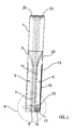
In der
Von den beiden Seitenwänden
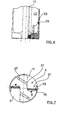
In der
Wie aus der
An der, das Schneidelement
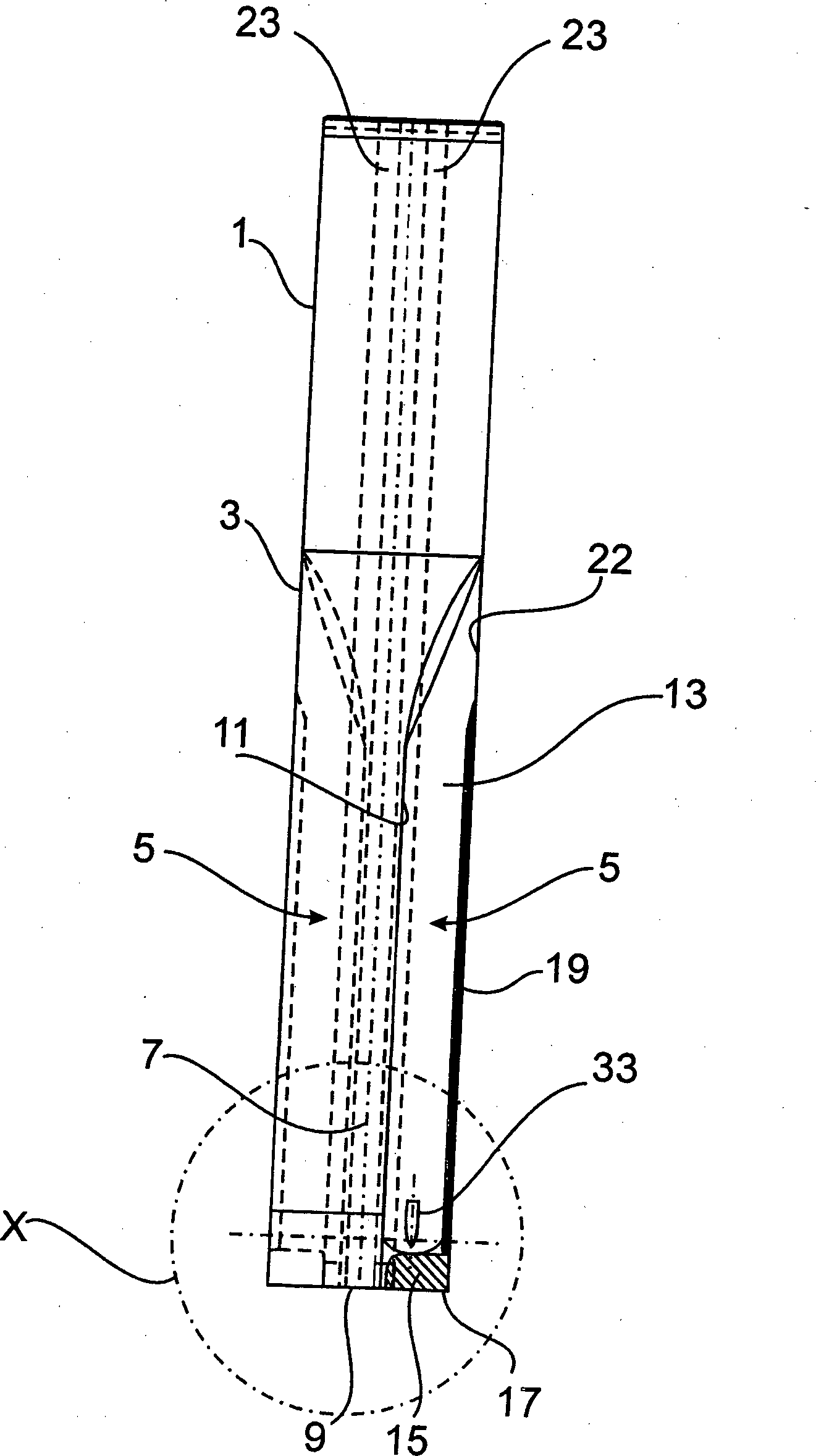
Wie aus der
Wie aus der
Um das Bohrwerkzeug mit einem Kühlmittel zu versorgen, erstrecken sich in der
In den
Bei einem Bohrvorgang werden die entstehenden Späne aufgrund der Zentrifugalkraft in die Nut
In den
Die Versorgung der Spanräume
In dem Vergleichsbeispiel der
Claims (15)
Priority Applications (9)
| Application Number | Priority Date | Filing Date | Title |
|---|---|---|---|
| DE102006027552A DE102006027552B4 (en) | 2006-06-14 | 2006-06-14 | Drilling tool, in particular for metallic materials |
| EP07785808A EP2032297B1 (en) | 2006-06-14 | 2007-06-06 | Drilling tool, particularly for metallic materials |
| DE502007006547T DE502007006547D1 (en) | 2006-06-14 | 2007-06-06 | DRILLING TOOL, ESPECIALLY FOR METALLIC MATERIALS |
| JP2009514675A JP5072961B2 (en) | 2006-06-14 | 2007-06-06 | Drilling tools especially for metal materials |
| US12/304,346 US20090155008A1 (en) | 2006-06-14 | 2007-06-06 | Drilling tool, in particular for metallic materials |
| PL07785808T PL2032297T3 (en) | 2006-06-14 | 2007-06-06 | Drilling tool, particularly for metallic materials |
| PCT/EP2007/005011 WO2007144098A2 (en) | 2006-06-14 | 2007-06-06 | Drilling tool, particularly for metallic materials |
| AT07785808T ATE499167T1 (en) | 2006-06-14 | 2007-06-06 | DRILLING TOOL ESPECIALLY FOR METALLIC MATERIALS |
| ES07785808T ES2359272T3 (en) | 2006-06-14 | 2007-06-06 | DRILL TOOL, IN PARTICULAR FOR METAL MATERIALS. |
Applications Claiming Priority (1)
| Application Number | Priority Date | Filing Date | Title |
|---|---|---|---|
| DE102006027552A DE102006027552B4 (en) | 2006-06-14 | 2006-06-14 | Drilling tool, in particular for metallic materials |
Publications (2)
| Publication Number | Publication Date |
|---|---|
| DE102006027552A1 DE102006027552A1 (en) | 2007-12-20 |
| DE102006027552B4 true DE102006027552B4 (en) | 2011-06-01 |
Family
ID=38544190
Family Applications (2)
| Application Number | Title | Priority Date | Filing Date |
|---|---|---|---|
| DE102006027552A Expired - Fee Related DE102006027552B4 (en) | 2006-06-14 | 2006-06-14 | Drilling tool, in particular for metallic materials |
| DE502007006547T Active DE502007006547D1 (en) | 2006-06-14 | 2007-06-06 | DRILLING TOOL, ESPECIALLY FOR METALLIC MATERIALS |
Family Applications After (1)
| Application Number | Title | Priority Date | Filing Date |
|---|---|---|---|
| DE502007006547T Active DE502007006547D1 (en) | 2006-06-14 | 2007-06-06 | DRILLING TOOL, ESPECIALLY FOR METALLIC MATERIALS |
Country Status (8)
| Country | Link |
|---|---|
| US (1) | US20090155008A1 (en) |
| EP (1) | EP2032297B1 (en) |
| JP (1) | JP5072961B2 (en) |
| AT (1) | ATE499167T1 (en) |
| DE (2) | DE102006027552B4 (en) |
| ES (1) | ES2359272T3 (en) |
| PL (1) | PL2032297T3 (en) |
| WO (1) | WO2007144098A2 (en) |
Families Citing this family (3)
| Publication number | Priority date | Publication date | Assignee | Title |
|---|---|---|---|---|
| JP2009241239A (en) * | 2008-03-31 | 2009-10-22 | Fuji Seiko Ltd | Drill and boring machining method |
| JP5256240B2 (en) * | 2010-04-09 | 2013-08-07 | 株式会社アライドマテリアル | Workpiece machining method using reamer |
| EP3736072A1 (en) * | 2019-05-07 | 2020-11-11 | AB Sandvik Coromant | Milling tool with coolant distributing holes |
Citations (5)
| Publication number | Priority date | Publication date | Assignee | Title |
|---|---|---|---|---|
| DE1552463A1 (en) * | 1966-09-15 | 1970-07-23 | Tiefbohr Technik Gmbh | Single-lip bur |
| DE7830277U1 (en) * | 1978-10-11 | 1980-03-20 | Komet Stahlhalter- Und Werkzeugfabrik Robert Breuning Gmbh, 7122 Besigheim | DRILLING TOOL FOR HOLES IN SOLID METAL MATERIAL |
| DE4307553A1 (en) * | 1992-03-12 | 1993-09-16 | Mitsubishi Materials Corp | Two fluted twist drill - has thick-webbed spiral fluted section at front end which runs out into thin-webbed straight-fluted section with wider flutes at rear end |
| EP0750960B1 (en) * | 1995-06-26 | 1999-08-04 | Walter Ag | Drill, particularly for metallic materials |
| DE19844363A1 (en) * | 1998-09-28 | 2000-03-30 | Baumgaertner Peter | Drilling tool has stock guiding device extending parallel to longitudinal axis of tool and facing clearing grooves to clear away chippings |
Family Cites Families (17)
| Publication number | Priority date | Publication date | Assignee | Title |
|---|---|---|---|---|
| US1407546A (en) * | 1919-10-15 | 1922-02-21 | Joseph Felix Alexander | Twist drill |
| US4160616A (en) * | 1977-10-03 | 1979-07-10 | Winblad Michael E | Drill containing minimum cutting material |
| US4220429A (en) * | 1979-04-16 | 1980-09-02 | Trw Inc. | Indexable insert drill |
| JPS6042012Y2 (en) * | 1981-03-16 | 1985-12-23 | 三菱マテリアル株式会社 | Throw-away drill mounting device |
| DE8536123U1 (en) * | 1985-12-21 | 1987-04-16 | Komet Stahlhalter- Und Werkzeugfabrik Robert Breuning Gmbh, 7122 Besigheim | Drilling tool |
| EP0320881B2 (en) * | 1987-12-14 | 2003-10-22 | Mitsubishi Materials Corporation | Twist drill |
| US5092718A (en) * | 1990-12-10 | 1992-03-03 | Metal Cutting Tools Corp. | Drill with replaceable cutting inserts |
| DE4231381A1 (en) * | 1992-09-19 | 1994-03-24 | Mitsubishi Materials Corp | drill |
| DE19522836A1 (en) * | 1995-06-23 | 1997-01-02 | Beck August Gmbh Co | Drilling tool |
| EP0839082B1 (en) * | 1995-07-14 | 2001-05-23 | Kennametal Inc. | Drill with cooling-lubricant channel |
| KR100485987B1 (en) * | 1996-02-29 | 2005-08-03 | 코메트 그룹 홀딩 게엠베하 | Drill tools for machine tools and methods of making the drill tools |
| EP0876867B1 (en) * | 1997-04-30 | 2002-06-26 | Seco Tools Ab | Drill |
| DE19834635C2 (en) * | 1998-07-31 | 2001-07-26 | Guehring Joerg | Drilling tool with an exchangeable cutting insert that is secured against loosening |
| SE519575C2 (en) * | 2000-04-11 | 2003-03-18 | Sandvik Ab | Metal-cutting drill has a tip formed of cutting edges of a specific geometry designed to optimise metal cutting speed |
| DE10030297A1 (en) * | 2000-06-27 | 2002-01-10 | Komet Stahlhalter Werkzeuge | drilling |
| ITMI20011365A1 (en) * | 2001-06-28 | 2002-12-28 | Camozzi Holding S P A | HIGH SPEED ROTARY TOOL WITH FLUID REFRIGERATED HARD MATERIAL INSERT |
| DE10333340A1 (en) * | 2003-07-23 | 2005-02-17 | Kennametal Inc. | Drill tool, comprising coolant ducts arranged parallel to central axis with outlets positioned in cutting grooves |
-
2006
- 2006-06-14 DE DE102006027552A patent/DE102006027552B4/en not_active Expired - Fee Related
-
2007
- 2007-06-06 WO PCT/EP2007/005011 patent/WO2007144098A2/en not_active Ceased
- 2007-06-06 PL PL07785808T patent/PL2032297T3/en unknown
- 2007-06-06 ES ES07785808T patent/ES2359272T3/en active Active
- 2007-06-06 DE DE502007006547T patent/DE502007006547D1/en active Active
- 2007-06-06 AT AT07785808T patent/ATE499167T1/en active
- 2007-06-06 EP EP07785808A patent/EP2032297B1/en not_active Not-in-force
- 2007-06-06 JP JP2009514675A patent/JP5072961B2/en active Active
- 2007-06-06 US US12/304,346 patent/US20090155008A1/en not_active Abandoned
Patent Citations (5)
| Publication number | Priority date | Publication date | Assignee | Title |
|---|---|---|---|---|
| DE1552463A1 (en) * | 1966-09-15 | 1970-07-23 | Tiefbohr Technik Gmbh | Single-lip bur |
| DE7830277U1 (en) * | 1978-10-11 | 1980-03-20 | Komet Stahlhalter- Und Werkzeugfabrik Robert Breuning Gmbh, 7122 Besigheim | DRILLING TOOL FOR HOLES IN SOLID METAL MATERIAL |
| DE4307553A1 (en) * | 1992-03-12 | 1993-09-16 | Mitsubishi Materials Corp | Two fluted twist drill - has thick-webbed spiral fluted section at front end which runs out into thin-webbed straight-fluted section with wider flutes at rear end |
| EP0750960B1 (en) * | 1995-06-26 | 1999-08-04 | Walter Ag | Drill, particularly for metallic materials |
| DE19844363A1 (en) * | 1998-09-28 | 2000-03-30 | Baumgaertner Peter | Drilling tool has stock guiding device extending parallel to longitudinal axis of tool and facing clearing grooves to clear away chippings |
Also Published As
| Publication number | Publication date |
|---|---|
| JP5072961B2 (en) | 2012-11-14 |
| EP2032297A2 (en) | 2009-03-11 |
| EP2032297B1 (en) | 2011-02-23 |
| JP2009539634A (en) | 2009-11-19 |
| ES2359272T3 (en) | 2011-05-20 |
| WO2007144098A2 (en) | 2007-12-21 |
| PL2032297T3 (en) | 2011-07-29 |
| ATE499167T1 (en) | 2011-03-15 |
| DE102006027552A1 (en) | 2007-12-20 |
| DE502007006547D1 (en) | 2011-04-07 |
| WO2007144098A3 (en) | 2008-04-10 |
| US20090155008A1 (en) | 2009-06-18 |
Similar Documents
| Publication | Publication Date | Title |
|---|---|---|
| DE3853518T3 (en) | Twist Drill. | |
| EP2237913B9 (en) | Drilling tool having point thinning | |
| DE102007037911B4 (en) | drill | |
| EP2205403B1 (en) | Chisel, particularly for motor-driven machines | |
| DE60016782T2 (en) | SELF DRILLING ANCHOR BOLT | |
| EP0685629A2 (en) | Rock drill bit | |
| DE112013005653T5 (en) | Cutting tool and cutting insert with a rear elastic slot | |
| DE102017120077A1 (en) | REDUCING MOLFE WITH COOLANT FLOW AND CUTTING ASSEMBLY USING SUCH A REDUCING MUFF | |
| DE19724373A1 (en) | Rock drill | |
| DE3131794A1 (en) | "DRILL" | |
| EP0707129B1 (en) | Drilling tool with tool body and cutting inserts | |
| DE102005005982A1 (en) | Gun drills | |
| DE2856363C2 (en) | Drilling tool | |
| DE19810193A1 (en) | Drilling tool | |
| DE102007062539B4 (en) | drilling | |
| DE202009013808U1 (en) | Cutter with a shaft-like basic shape | |
| DE69013340T2 (en) | Self-drilling screw with cutting edges curved towards the head side. | |
| EP1083295B1 (en) | Drilling tool | |
| EP1604793A1 (en) | Drill | |
| EP2032297B1 (en) | Drilling tool, particularly for metallic materials | |
| CH637048A5 (en) | DRILLING TOOL FOR HOLES IN METAL FULL MATERIAL OF WORKPIECES. | |
| DE112019006105T5 (en) | Drills and insert for drills with improved centering ability and cutting performance | |
| EP3656494A1 (en) | Step drill | |
| DE102014203327A1 (en) | drilling | |
| DE102008062298B4 (en) | Drill body |
Legal Events
| Date | Code | Title | Description |
|---|---|---|---|
| OP8 | Request for examination as to paragraph 44 patent law | ||
| R018 | Grant decision by examination section/examining division | ||
| R020 | Patent grant now final |
Effective date: 20110902 |
|
| R119 | Application deemed withdrawn, or ip right lapsed, due to non-payment of renewal fee |