EP0749628B1 - Einrichtung zur funktionssicherheitsüberwachung von leistungsschalteinrichtungen (diagnosegerät) - Google Patents
Einrichtung zur funktionssicherheitsüberwachung von leistungsschalteinrichtungen (diagnosegerät) Download PDFInfo
- Publication number
- EP0749628B1 EP0749628B1 EP95910445A EP95910445A EP0749628B1 EP 0749628 B1 EP0749628 B1 EP 0749628B1 EP 95910445 A EP95910445 A EP 95910445A EP 95910445 A EP95910445 A EP 95910445A EP 0749628 B1 EP0749628 B1 EP 0749628B1
- Authority
- EP
- European Patent Office
- Prior art keywords
- microprocessor
- power switching
- microprocessor unit
- current
- memory
- Prior art date
- Legal status (The legal status is an assumption and is not a legal conclusion. Google has not performed a legal analysis and makes no representation as to the accuracy of the status listed.)
- Expired - Lifetime
Links
Images
Classifications
-
- H—ELECTRICITY
- H02—GENERATION; CONVERSION OR DISTRIBUTION OF ELECTRIC POWER
- H02H—EMERGENCY PROTECTIVE CIRCUIT ARRANGEMENTS
- H02H11/00—Emergency protective circuit arrangements for preventing the switching-on in case an undesired electric working condition might result
- H02H11/005—Emergency protective circuit arrangements for preventing the switching-on in case an undesired electric working condition might result in case of too low isolation resistance, too high load, short-circuit; earth fault
-
- H—ELECTRICITY
- H01—ELECTRIC ELEMENTS
- H01H—ELECTRIC SWITCHES; RELAYS; SELECTORS; EMERGENCY PROTECTIVE DEVICES
- H01H11/00—Apparatus or processes specially adapted for the manufacture of electric switches
-
- H—ELECTRICITY
- H01—ELECTRIC ELEMENTS
- H01H—ELECTRIC SWITCHES; RELAYS; SELECTORS; EMERGENCY PROTECTIVE DEVICES
- H01H11/00—Apparatus or processes specially adapted for the manufacture of electric switches
- H01H11/0062—Testing or measuring non-electrical properties of switches, e.g. contact velocity
- H01H2011/0068—Testing or measuring non-electrical properties of switches, e.g. contact velocity measuring the temperature of the switch or parts thereof
-
- H—ELECTRICITY
- H01—ELECTRIC ELEMENTS
- H01H—ELECTRIC SWITCHES; RELAYS; SELECTORS; EMERGENCY PROTECTIVE DEVICES
- H01H33/00—High-tension or heavy-current switches with arc-extinguishing or arc-preventing means
- H01H33/60—Switches wherein the means for extinguishing or preventing the arc do not include separate means for obtaining or increasing flow of arc-extinguishing fluid
- H01H33/66—Vacuum switches
- H01H33/666—Operating arrangements
Definitions
- the invention relates to a device for functional safety monitoring of power switching devices, in particular vacuum circuit breakers in medium voltage switchgear, with data processing microprocessor units consisting of a microprocessor, a microprocessor control and a processor-oriented storage device, with current detection devices for detection and conversion a nominal current of the power switching device and the detection and revaluation of the drive of the mobile Part of the power switching device causing motor current, and with a current detection device with current transformers for signal adaptation
- Such a defined device for functional safety monitoring of power switching devices is known from WO 93/23760.
- Different operating parameters of critical power switchgear are registered here by corresponding monitoring devices and stored in monitoring-specific storage devices. This data is then queried by a higher-level computer unit and compared and evaluated with existing data from non-critical power switchgear. In the event of larger deviations, maintenance processes can be initiated or complete shutdown processes can be triggered if necessary.
- a test program for the determination of environmental Influences on the power switching devices mentioned above is for example through the publication "Developments in Design and Performance of EHV Switching Equipment ", IEEE Conference Publication Number 182, 1979, pages 126 to 129 described. Then electrical switching performance tests with the help of a synthetic test circuit as well a series of mechanical tests to: for example over a certain number of expired switching operations u. a. the switching capacity of the actual switching elements and their contact resistance and the immediate vicinity of the contact pieces, such as to check the gas pressure ratios. Also be mechanical loads on moving parts of the power switchgear examined, so depending on the Frequency of switching to functional safety-relevant To be able to close data of the power switching devices.
- a microprocessor unit defined in this way as a device for function monitoring of power switching devices, all operating parameters can be entered directly as non-calculated data information and data can be produced by means of suitable linking mechanisms, from which appropriate statistical evaluations can be used to draw conclusions about the state of the power switching device currently being examined.
- An essential component of this device according to the invention contains the angular pulse rotation direction detection device, with which both the size and the course of the switching angle of the switching shaft within certain time sequences as well as the rotation angle speed itself can be transmitted to the microprocessor as data.
- the microprocessor with the current detection device has current detection available in two ways. On the one hand the motor current flowing through the motor to lift the spring drive and on the other hand the coil current generated in the current transformer is measured.
- the actual current detection device essentially consists of two parts, the actual current transformer and the signal adaptation with the filter unit for the elimination of interference voltages that may be interfered with.
- the output signal generated by the current transformer is proportional to the flowing nominal current, so that, for example, with a nominal current of 100 A in the transformer can be represented by an alternating current of 100 mA.
- This alternating current is converted in a known manner into a voltage that can be processed by an AD converter of the microprocessor, rectified and filtered.
- the ambient temperature within the power switching device is detected with the sensor device and is likewise fed to the microprocessor via the filter device and an AD converter.
- the individual switching functions of the power switching devices in particular the power switch, can be queried in the service department. For this purpose, a defined measuring voltage is applied to the linked power switching devices and the corresponding incoming signals are transmitted to the microprocessor via the further filter device and the downstream pulse shaping device.
- the memory device is configured in such a way that the lower address area is arranged in the external random access memory so that, for example, the fast data transfer can be used in a photoelectric oscillogram creation.
- the data exchange caused by the initialization between the programmable read-only memory and the random access memory is controlled by the multiple data transmission unit.
- the device for functional safety monitoring of the power switching devices in simple way with the power switching devices to be monitored connected and the necessary for evaluation Data can be collected without difficulty.
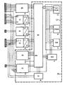
- the invention is illustrated in an exemplary embodiment explained in more detail, in which the individual among themselves linked function blocks for functional safety monitoring the power switching devices of the better For reasons of overview are only shown in extracts.
- the device for the functional safety monitoring of power switching devices contains the data processors Microprocessor unit ME, which essentially consists of the microprocessor MP with the appropriate microprocessor control MS and the processor-oriented storage device SP consists. At the microprocessor MP is with the help of the angular pulse direction detection device WD the movement of the moving part of the respective power switching device in the form of microprocessor-processable data transfer.
- the microprocessor unit ME is also included a current detection device SE connected to the detection and conversion of the nominal current of the power switching device in a coil current SS and the detection and Revaluation of the drive of the moving part of the power switchgear effecting motor current SM is used.
- the current detection device SE also contains the Current converter I / U, which in cooperation with the Power voltage filter unit SF the angular pulse direction of rotation data transmits directly to the microprocessor MP.
- the microprocessor unit ME with the Ambient temperature in the power switching device Sensor device SN transmit output signals that in the same way via the filter unit FE and the analog-digital converter unit AD transmitted to the microprocessor MP become.
- a digital input device not shown EG, with which the switching functions of the respective Load power switching device are recognized, their incoming signals L1 to L3 also via a filter device FI led to subsequently under the influence of taxes the pulse shaping device ST also to the microprocessor MP to be able to be transmitted.
- the interface conversion unit SU can have corresponding input signals to control the microprocessor unit ME directly to the Microprocessor MP can be entered.
- the memory device SP of the microprocessor unit ME is presented both by the random access memory RAM and by the releasably programmable read-only memory EPROM, the targeted data control of which is carried out via the multiple data transmission unit MUX.
- the erasable programmable read-only memory EPROM contains a fast access area flash EPROM in order to enable the write and erase processes caused by fast write processes when producing oscillograms.
- the microprocessor control MS also contains a voltage detector (not shown) which, when the supply voltage device VS falls below a minimum permissible supply voltage, generates the power failure signal NAU, which leads to the termination of the data determination during the functional safety monitoring of the power switching devices.
- the entire device is arranged in multilayer technology on a printed circuit board, which may also be located outside of the power switching devices to be diagnosed.
- the information determined by appropriate sensors within the power switching devices is fed directly to the printed circuit board via electromagnetically shieldable connector cables.
- the directly detectable and recorded in oscillograms such as motor, tripping and short-circuit currents, operating voltages and changes in angle of rotation in values and speeds with corresponding temperature changes, all serve to individually characterize the power switching device examined in each case, so that reliable statements about their motor and switching functions available.
- the individual power switching device values can then be subjected to a temperature, voltage and / or time-compensated classification as required, so that with a correspondingly large number of comparison values of a certain type of system types, for example, the scatter ranges of certain individual features can be produced. This makes it possible to make statements about the availability of such power switching devices in the current state and can be used on site for both acceptance and commissioning of the power switching devices.
Description
Hier werden unterschiedliche Betriebsparameter von kritischen Leistungsschaltanlagen durch entsprechende Überwachungseinrichtungen registriert und in überwachungsindividuellen Speichereinrichtungen abgespeichert. Anschließend werden diese Daten von einer übergeordneten Rechnereinheit abgefragt und mit bereits vorhandenen Daten unkritisch arbeitender Leistungsschaltanlagen verglichen und ausgewertet. Bei größeren Abweichungen können im Bedarfsfall Wartungsvorgänge veranlaßt oder auch gänzliche Abschaltvorgänge ausgelöst werden.
Die der Erfindung zugrundeliegende Aufgabe besteht darin, diese bekannten Verfahren hinsichtlich ihrer Auswertung wesentlich zu erweitern und insbesondere die einzelnen Verfahrensschritte so zu präzisieren, daß zu den im Normalvorhandenen rein mechanischen Gegebenheiten möglichst sämtliche relevanten Einflußgrößen zur Bewertung der Funktionssicherheit derartiger Leistungsschalteinrichtungen mit einbezogen werden können. Erfindungsgemäß wird dies durch die folgenden Merkmale erreicht:
Darüber hinaus wird mit der Sensoreinrichtung die Umgebungstemperatur innerhalb der Leistungsschalteinrichtung erfaßt und gleichermaßen über die Filtereinrichtung und einem AD-Wandler dem Mikroprozessor zugeführt.
Mit der digitalen Eingabeeinrichtung sind im Servicedienst die einzelnen Schaltfunktionen der Leistungsschalteinrichtungen, insbesondere der Leistungsschalter, abzufragen. Dazu wird eine definierte Meßspannung an die verketteten Leistungsschalteinrichtungen angelegt und die entsprechend eingehenden Signale über die weitere Filtereinrichtung und die nachgeschaltete Impulsformeinrichtung an den Mikroprozessor übertragen.
Darüber hinaus wird der durch die Initialisierung bedingte Datenaustausch zwischen den programmierbaren Nur-Lese-Speicher und dem wahlfreien Zugriffsspeicher durch die Mehrfach-Datenübertragungseinheit gesteuert.
Die Mikroprozessorsteuerung MS enthält außerdem einen nicht dargestellten Spannungsdetektor, der beim Unterschreiten einer minimal zulässigen Versorgungsspannung durch die Versorgungsspannungseinrichtung VS das Netzausfallsignal NAU erzeugt, daß zum Abbruch der Datenermittlung bei der Funktionssicherheitsüberwachung der Leistungsschalteinrichtungen führt.
Die individuellen Leistungsschalteinrichtungswerte können dann je nach Bedarf einer temperatur-, spannungs- und/oder zeitkompensierten Klassifizierung unterzogen werden, so daß bei entsprechend großer Anzahl von Vergleichswerten einer bestimmten Art von Anlagentypen beispielsweise die Streubandbreiten bestimmter Einzelmerkmale produzierbar sind. Damit sind Aussagen über die Verfügbarkeit derartiger Leistungsschalteinrichtungen im Ist-Zustand möglich und können vor Ort sowohl zur Abnahme als auch zur Inbetriebsetzung der Leistungsschalteinrichtungen herangezogen werden.
Mit diesen Einrichtungen können darüber hinaus auch Aussagen und Prognosen über das zukünftige Funktionsverhalten der Leistungsschalteinrichtung getroffen werden, wodurch deren Funktionssicherheit erheblich gesteigert ist. Andererseits ist mit dem Einsatz dieser Einrichtung für den Fall, daß die Anlagen zuverlässig arbeiten, eine erhebliche Verlängerung der Wartungsintervalle und damit eine präventive Schadensbegrenzung erreichbar.
Claims (5)
- Einrichtung zur Funktionssicherheitsüberwachung von Leistungsschalteinrichtungen, insbesondere von Vakuumleistungsschalter in Mittelspannungsschaltanlagen, mit datenverarbeitenden Mikroprozessoreinheiten bestehend aus einem Mikroprozessor , einer Mikroprozessorsteuerung und einer prozessororientierten Speichereinrichtung, mit Stromerfassungseinrichtungen zur Erkennung und Umwertung eines Nennstromes der Leistungschalteinrichtung und der Erkennung und Umwertung eines den Antrieb des beweglichen Teils der Leistungsschalteinrichtung bewirkenden Motorstroms, und mit einer Stromerfassungseinrichtung mit Stromwandlern zur Signalanpassung,
gekennzeichnet durch die Merkmale1.1 die Mikroprozessoreinheit (ME) steht mit einer Winkelimpuls-Drehrichtungs-Erkennungseinrichtung (WD) in Verbindung, die die Umsetzung einer Bewegung eines beweglichen Teils der jeweiligen Leistungsschalteinrichtung in mikroprozessorverarbeitbare Daten bewirkt, die in der Speichereinrichtung (SP)prozessororientiert gespeichert sind,1.2 der Stromerfassungseinrichtung (SE) sind ein Stromspannungswandler (I/U) und eine Störspannungsfiltereinrichtung (SF) nachgeschaltet, deren Stromwerte als Daten in der Speichereinrichtung (SP) prozessororientiert gespeichert sind,1.3 die Mikroprozessoreinheit (ME) ist mit einer die Umgebungstemperatur in der Leistungsschalteinrichtung erfassenden Sensoreinrichtung (SN) verbunden, deren Ausgangssignal über eine Filtereinheit (FE) und eine Analog-Digital-Wandlereinheit (AD) der Mikroprozessoreinrichtung (ME) zugeführt und als Daten in der Speichereinrichtung (SP) prozessororientiert gespeichert sind,1.4 die Mikroprozessoreinheit (ME) ist mit einer Schaltfunktionen der jeweiligen Leistungsschalteinrichtung erkennenden digitalen Eingabeeinrichtung (EG) verbunden, deren eingehende Signale (L1-3) über eine weitere Filtereinrichtung (FI) und eine Impulsformeinrichtung (ST) der Mikroprozessoreinheit (ME) zugeführt und als Daten in der Speichereinrichtung (SP) prozessororientiert gespeichert sind,1.5 die Mikroprozessoreinheit (ME) steht mit einer Eingangssteuersignale empfangenden Schnittstellenumsetzeinheit (SU) in Verbindung,1.6 die in der Speichereinrichtung (SP) prozessororientiert gespeicherten Daten sind von der digitalen Eingabeeinrichtung (EG), mit der die Schaltfunktionen der jeweiligen Leistungsschalteinrichtung erkannt werden, mittels geeigneter Verknüpfungsmechanismen prozessororientiert abrufbar. - Einrichtung zur Funktionssicherheitsüberwachung von Leistungsschalteinrichtungen nach Anspruch 1,
gekennzeichnet durch die Merkmale2.1 die Speichereinrichtung (SP) ist mit einem Speicherbereich ausgestattet, der durch einen wahlfreien Zugriffsspeicher (RAM) und einen löschbar programmierbaren Nur-Lese-Speicher (EPROM) repräsentiert ist,2.2 die Speichereinrichtung (SP) steht mit der Mikroprozessoreinheit (ME) über eine Mehrfach-Datenübertragungseinheit (MUX) in Verbindung. - Einrichtung zur Funktionsüberwachung von Leistungsschalteinrichtungen nach Anspruch 2,
gekennzeichnet durch das Merkmal3.1 der löschbar programmierbare Nur-Lese-Speicher (EPROM) enthält einen Schreib- und Löschvorgang durch schnelle Schreibvorgänge der Mikroprozessoreinheit (ME) aufnehmenden Schnellzugriffsbereich (Flash-EPROM), deren Zustand in einem darin integrierten Statusregister gespeichert und auch während der Schreib-Löschvorgänge abrufbar ist. - Einrichtung zur Funktionsüberwachung von Leistungsschalteinrichtungen nach Anspruch 1,
gekennzeichnet durch die Merkmale4.1 die Mikroprozessorsteuerung (MS) ist mit einem Spannungsdetektor ausgestattet, der beim Unterschreiten einer minimal zulässigen Versorgungsspannung der Mikroprozessoreinheit (ME) ein Störfallsignal erzeugt,4.2 das Störfallsignal ist der Mikroprozessoreinheit (ME) als Netzausfallsignal (NAU) übertragbar. - Einrichtung zur Funktionsüberwachung von Leistungsschalteinrichtungen nach einem der vorangegangenen Ansprüche 1 bis 4,
gekennzeichnet durch die Merkmale5.1 die Mikroprozessoreinheit (ME) ist in Multilayeranordnung auf einer Flachbaugruppe angeordnet,5.2 der Mikroprozessoreinheit (ME) sind eine die Anzahl der sensorisch erfaßbaren Funktionsüberwachungen entsprechende Zahl von elektromagnetisch abschirmbaren Steckverbinderleitungen zugeführt.
Applications Claiming Priority (3)
| Application Number | Priority Date | Filing Date | Title |
|---|---|---|---|
| DE4408631 | 1994-03-09 | ||
| DE4408631A DE4408631C2 (de) | 1994-03-09 | 1994-03-09 | Einrichtung zur Funktionssicherheitsüberwachung von Leistungsschalteinrichtungen (Diagnosegerät) |
| PCT/DE1995/000296 WO1995024725A1 (de) | 1994-03-09 | 1995-02-22 | Einrichtung zur funktionssicherheitsüberwachung von leistungsschalteinrichtungen (diagnosegerät) |
Publications (2)
| Publication Number | Publication Date |
|---|---|
| EP0749628A1 EP0749628A1 (de) | 1996-12-27 |
| EP0749628B1 true EP0749628B1 (de) | 1999-09-08 |
Family
ID=6512757
Family Applications (1)
| Application Number | Title | Priority Date | Filing Date |
|---|---|---|---|
| EP95910445A Expired - Lifetime EP0749628B1 (de) | 1994-03-09 | 1995-02-22 | Einrichtung zur funktionssicherheitsüberwachung von leistungsschalteinrichtungen (diagnosegerät) |
Country Status (12)
| Country | Link |
|---|---|
| US (1) | US5801461A (de) |
| EP (1) | EP0749628B1 (de) |
| JP (1) | JP3512188B2 (de) |
| KR (1) | KR100364921B1 (de) |
| AT (1) | ATE184421T1 (de) |
| CA (1) | CA2185017A1 (de) |
| DE (2) | DE4408631C2 (de) |
| DK (1) | DK0749628T3 (de) |
| ES (1) | ES2136837T3 (de) |
| TW (1) | TW279211B (de) |
| UA (1) | UA28039C2 (de) |
| WO (1) | WO1995024725A1 (de) |
Cited By (1)
| Publication number | Priority date | Publication date | Assignee | Title |
|---|---|---|---|---|
| DE102010026528A1 (de) * | 2010-07-08 | 2012-01-12 | Areva Energietechnik Gmbh | Elektrischer Leistungsschalter und Verfahren zum Betreiben eines elektrischen Leistungsschalters |
Families Citing this family (12)
| Publication number | Priority date | Publication date | Assignee | Title |
|---|---|---|---|---|
| DE19734224C1 (de) * | 1997-08-07 | 1999-02-04 | Siemens Ag | Verfahren und Vorrichtung zur Bestimmung von schaltgerätespezifischen Daten an Kontakten in Schaltgeräten und/oder zur Bestimmung von betriebsspezifischen Daten im damit geschalteten Netz |
| US6362445B1 (en) * | 2000-01-03 | 2002-03-26 | Eaton Corporation | Modular, miniaturized switchgear |
| US7463036B2 (en) * | 2006-12-28 | 2008-12-09 | General Electric Company | Measurement of analog coil voltage and coil current |
| WO2009046747A1 (de) * | 2007-10-08 | 2009-04-16 | Siemens Aktiengesellschaft | Verfahren zur prüfung des freiauslöseverhaltens eines elektromechanisch betätigbaren, leistungsschalters und vorrichtung zur durchführung des verfahrens |
| WO2009046746A1 (de) * | 2007-10-08 | 2009-04-16 | Siemens Aktiengesellschaft | Verfahren zur prüfung des freiauslöseverhaltens eines mechanisch betätigbaren leistungsschalters und vorrichtung zur durchführung des verfahrens |
| ES2523495T3 (es) * | 2009-04-03 | 2014-11-26 | Enel Distribuzione S.P.A. | Circuito disyuntor eléctrico y procedimiento para operar un circuito disyuntor eléctrico |
| DE102010041998A1 (de) * | 2010-10-05 | 2012-04-05 | Robert Bosch Gmbh | Verfahren zur Vorhersage der Einsatzfähigkeit eines Relais oder eines Schützes |
| RU2013144196A (ru) | 2011-03-02 | 2015-04-10 | Франклин Фьюэлинг Системз, Инк. | Система отслеживания плотности газа |
| CN103163455A (zh) * | 2011-12-15 | 2013-06-19 | 海洋王照明科技股份有限公司 | 温度保护开关的寿命测试方法 |
| WO2013126397A1 (en) | 2012-02-20 | 2013-08-29 | Franklin Fueling Systems, Inc. | Moisture monitoring system |
| EP3043187B1 (de) * | 2015-01-09 | 2020-01-01 | ABB Schweiz AG | Verfahren zur Bestimmung des Betriebszustands einer elektromagnetischen Mittelspannungsschaltvorrichtung |
| CN105676018B (zh) * | 2015-11-23 | 2018-07-31 | 江苏省电力公司 | 一种基于稳态学习机制的电网低频振荡模糊综合预警方法 |
Family Cites Families (9)
| Publication number | Priority date | Publication date | Assignee | Title |
|---|---|---|---|---|
| US3765015A (en) * | 1971-09-20 | 1973-10-09 | Data General Corp | Switch monitoring circuitry |
| DE2921095C2 (de) * | 1979-05-22 | 1983-03-31 | Auergesellschaft Gmbh, 1000 Berlin | Verfahren zur Überwachung des Schaltzustandes von Schaltelementen |
| DE3001940C2 (de) * | 1980-01-21 | 1983-01-27 | Siemens AG, 1000 Berlin und 8000 München | Anordnung zur Ermittlung der Schaltstellung eines Schalters und zur Überwachung der zugehörigen Leitung auf Kurzschluß und Unterbrechung |
| JPH0721981B2 (ja) * | 1987-04-13 | 1995-03-08 | 株式会社日立製作所 | 開閉器の動作監視装置 |
| DE3822342A1 (de) * | 1987-07-09 | 1989-01-19 | Mitsubishi Electric Corp | Strompfadunterbrecher |
| DE4131828C1 (de) * | 1991-09-20 | 1993-04-08 | Siemens Ag, 8000 Muenchen, De | |
| EP0594830A4 (de) * | 1992-05-12 | 1994-11-23 | Square D Co | Überwachungssystem für sicherkeitsautomaten und alarmeinrichtung zur vorbeugenden wartung. |
| DE4318189A1 (de) * | 1993-06-01 | 1994-12-08 | Abb Management Ag | Vorrichtung und Verfahren zur Überwachung einer Schalterstellung |
| US5629869A (en) * | 1994-04-11 | 1997-05-13 | Abb Power T&D Company | Intelligent circuit breaker providing synchronous switching and condition monitoring |
-
1994
- 1994-03-09 DE DE4408631A patent/DE4408631C2/de not_active Expired - Fee Related
-
1995
- 1995-01-26 TW TW084100692A patent/TW279211B/zh active
- 1995-02-22 AT AT95910445T patent/ATE184421T1/de not_active IP Right Cessation
- 1995-02-22 US US08/702,642 patent/US5801461A/en not_active Expired - Lifetime
- 1995-02-22 CA CA002185017A patent/CA2185017A1/en not_active Abandoned
- 1995-02-22 JP JP52314995A patent/JP3512188B2/ja not_active Expired - Fee Related
- 1995-02-22 KR KR1019960704961A patent/KR100364921B1/ko not_active IP Right Cessation
- 1995-02-22 DK DK95910445T patent/DK0749628T3/da active
- 1995-02-22 EP EP95910445A patent/EP0749628B1/de not_active Expired - Lifetime
- 1995-02-22 WO PCT/DE1995/000296 patent/WO1995024725A1/de active IP Right Grant
- 1995-02-22 ES ES95910445T patent/ES2136837T3/es not_active Expired - Lifetime
- 1995-02-22 UA UA96093471A patent/UA28039C2/uk unknown
- 1995-02-22 DE DE59506797T patent/DE59506797D1/de not_active Expired - Fee Related
Cited By (1)
| Publication number | Priority date | Publication date | Assignee | Title |
|---|---|---|---|---|
| DE102010026528A1 (de) * | 2010-07-08 | 2012-01-12 | Areva Energietechnik Gmbh | Elektrischer Leistungsschalter und Verfahren zum Betreiben eines elektrischen Leistungsschalters |
Also Published As
| Publication number | Publication date |
|---|---|
| EP0749628A1 (de) | 1996-12-27 |
| UA28039C2 (uk) | 2000-10-16 |
| DE4408631C2 (de) | 1996-11-14 |
| ES2136837T3 (es) | 1999-12-01 |
| TW279211B (de) | 1996-06-21 |
| KR970701915A (ko) | 1997-04-12 |
| KR100364921B1 (ko) | 2003-04-10 |
| WO1995024725A1 (de) | 1995-09-14 |
| JPH09510041A (ja) | 1997-10-07 |
| CA2185017A1 (en) | 1995-09-14 |
| ATE184421T1 (de) | 1999-09-15 |
| JP3512188B2 (ja) | 2004-03-29 |
| DE59506797D1 (de) | 1999-10-14 |
| DE4408631A1 (de) | 1995-11-09 |
| DK0749628T3 (da) | 2000-04-03 |
| US5801461A (en) | 1998-09-01 |
Similar Documents
| Publication | Publication Date | Title |
|---|---|---|
| EP0749628B1 (de) | Einrichtung zur funktionssicherheitsüberwachung von leistungsschalteinrichtungen (diagnosegerät) | |
| EP2980659B1 (de) | Vorrichtung und Verfahren zum Überwachen und Schalten eines Lastkreises | |
| EP1695055B1 (de) | Messeinrichtung, insbesondere temperaturmessumformer | |
| DE102016107598B3 (de) | Vorrichtung und verfahren zum überwachen eines hochvolt-schützes in einem fahrzeug | |
| WO2013057216A1 (de) | Vorrichtung zur positionserfassung einer aufzugkabine | |
| DE102004021380A1 (de) | Vorrichtung zur Stromversorgung | |
| EP3557598B1 (de) | Sicherheitsschalter | |
| DE102014221042A1 (de) | Fehlerstromschutzvorrichtung zur Ableitstromerfassung | |
| EP0864099A2 (de) | Verfahren und einrichtung zur überprüfung elektrischer antriebe | |
| EP2434358A1 (de) | Verfahren zum Betreiben eines redundanten Systems und System | |
| EP2181907A1 (de) | Weichendiagnosesystem | |
| EP0609261B1 (de) | Einrichtung zur überprüfung eines elektrischen antriebs | |
| EP0809361B1 (de) | Elektronisches Schaltgerät und Schaltungsanordnung zur Überwachung einer Anlage | |
| EP0295593A2 (de) | Einzelidentifikation | |
| EP2899822B1 (de) | Elektrische Schutzanordnung für eine Elektroinstallation sowie dazugehöriges Verfahren | |
| DE19620065A1 (de) | Schaltungsanordnung zur Überwachung des fehlerfreien und/oder zur Erkennung eines fehlerbehafteten Zustands einer Anlage | |
| DE102017126754A1 (de) | Eingangsschaltung zum fehlersicheren Einlesen eines analogen Eingangssignals | |
| WO2022128558A1 (de) | Überwachung von leistungselektrischen einrichtungen | |
| DE4326942A1 (de) | Einrichtung zur Überwachung eines Auslösekreises eines elektrischen Betriebsmittels | |
| DE102016207499B3 (de) | Schaltanlage mit Mensch-Maschine-Schnittstelle sowie Verfahren zum Betreiben dieser Schaltanlage | |
| EP0500997A1 (de) | Anordnung zur Beeinflussung von Schaltgeräten | |
| DE102019220444B4 (de) | Fernantrieb und Parametrier-Verfahren | |
| EP1333552B1 (de) | Verfahren und Vorrichtung zur Detektion von Fehlerzuständen bei der Energieversorgung einer Last | |
| DE3640643C2 (de) | ||
| DE3642649C2 (de) |
Legal Events
| Date | Code | Title | Description |
|---|---|---|---|
| PUAI | Public reference made under article 153(3) epc to a published international application that has entered the european phase |
Free format text: ORIGINAL CODE: 0009012 |
|
| 17P | Request for examination filed |
Effective date: 19960806 |
|
| AK | Designated contracting states |
Kind code of ref document: A1 Designated state(s): AT BE CH DE DK ES FR GB IT LI NL SE |
|
| 17Q | First examination report despatched |
Effective date: 19961217 |
|
| GRAG | Despatch of communication of intention to grant |
Free format text: ORIGINAL CODE: EPIDOS AGRA |
|
| GRAG | Despatch of communication of intention to grant |
Free format text: ORIGINAL CODE: EPIDOS AGRA |
|
| GRAH | Despatch of communication of intention to grant a patent |
Free format text: ORIGINAL CODE: EPIDOS IGRA |
|
| GRAH | Despatch of communication of intention to grant a patent |
Free format text: ORIGINAL CODE: EPIDOS IGRA |
|
| GRAA | (expected) grant |
Free format text: ORIGINAL CODE: 0009210 |
|
| AK | Designated contracting states |
Kind code of ref document: B1 Designated state(s): AT BE CH DE DK ES FR GB IT LI NL SE |
|
| REF | Corresponds to: |
Ref document number: 184421 Country of ref document: AT Date of ref document: 19990915 Kind code of ref document: T |
|
| REG | Reference to a national code |
Ref country code: CH Ref legal event code: NV Representative=s name: SIEMENS SCHWEIZ AG Ref country code: CH Ref legal event code: EP |
|
| REF | Corresponds to: |
Ref document number: 59506797 Country of ref document: DE Date of ref document: 19991014 |
|
| ET | Fr: translation filed | ||
| ITF | It: translation for a ep patent filed |
Owner name: STUDIO JAUMANN P. & C. S.N.C. |
|
| REG | Reference to a national code |
Ref country code: ES Ref legal event code: FG2A Ref document number: 2136837 Country of ref document: ES Kind code of ref document: T3 |
|
| GBT | Gb: translation of ep patent filed (gb section 77(6)(a)/1977) |
Effective date: 19991118 |
|
| REG | Reference to a national code |
Ref country code: DK Ref legal event code: T3 |
|
| PLBE | No opposition filed within time limit |
Free format text: ORIGINAL CODE: 0009261 |
|
| STAA | Information on the status of an ep patent application or granted ep patent |
Free format text: STATUS: NO OPPOSITION FILED WITHIN TIME LIMIT |
|
| 26N | No opposition filed | ||
| PGFP | Annual fee paid to national office [announced via postgrant information from national office to epo] |
Ref country code: CH Payment date: 20010511 Year of fee payment: 7 |
|
| REG | Reference to a national code |
Ref country code: GB Ref legal event code: IF02 |
|
| PGFP | Annual fee paid to national office [announced via postgrant information from national office to epo] |
Ref country code: AT Payment date: 20020123 Year of fee payment: 8 |
|
| PGFP | Annual fee paid to national office [announced via postgrant information from national office to epo] |
Ref country code: DK Payment date: 20020205 Year of fee payment: 8 |
|
| PGFP | Annual fee paid to national office [announced via postgrant information from national office to epo] |
Ref country code: SE Payment date: 20020221 Year of fee payment: 8 |
|
| PGFP | Annual fee paid to national office [announced via postgrant information from national office to epo] |
Ref country code: BE Payment date: 20020225 Year of fee payment: 8 |
|
| PG25 | Lapsed in a contracting state [announced via postgrant information from national office to epo] |
Ref country code: LI Free format text: LAPSE BECAUSE OF NON-PAYMENT OF DUE FEES Effective date: 20020228 Ref country code: CH Free format text: LAPSE BECAUSE OF NON-PAYMENT OF DUE FEES Effective date: 20020228 |
|
| REG | Reference to a national code |
Ref country code: CH Ref legal event code: PL |
|
| PGFP | Annual fee paid to national office [announced via postgrant information from national office to epo] |
Ref country code: NL Payment date: 20030204 Year of fee payment: 9 |
|
| PGFP | Annual fee paid to national office [announced via postgrant information from national office to epo] |
Ref country code: GB Payment date: 20030206 Year of fee payment: 9 |
|
| PG25 | Lapsed in a contracting state [announced via postgrant information from national office to epo] |
Ref country code: AT Free format text: LAPSE BECAUSE OF NON-PAYMENT OF DUE FEES Effective date: 20030222 |
|
| PG25 | Lapsed in a contracting state [announced via postgrant information from national office to epo] |
Ref country code: SE Free format text: LAPSE BECAUSE OF NON-PAYMENT OF DUE FEES Effective date: 20030223 |
|
| PGFP | Annual fee paid to national office [announced via postgrant information from national office to epo] |
Ref country code: ES Payment date: 20030224 Year of fee payment: 9 |
|
| PG25 | Lapsed in a contracting state [announced via postgrant information from national office to epo] |
Ref country code: DK Free format text: LAPSE BECAUSE OF NON-PAYMENT OF DUE FEES Effective date: 20030228 Ref country code: BE Free format text: LAPSE BECAUSE OF NON-PAYMENT OF DUE FEES Effective date: 20030228 |
|
| EUG | Se: european patent has lapsed | ||
| REG | Reference to a national code |
Ref country code: DK Ref legal event code: EBP |
|
| PG25 | Lapsed in a contracting state [announced via postgrant information from national office to epo] |
Ref country code: GB Free format text: LAPSE BECAUSE OF NON-PAYMENT OF DUE FEES Effective date: 20040222 |
|
| PG25 | Lapsed in a contracting state [announced via postgrant information from national office to epo] |
Ref country code: ES Free format text: LAPSE BECAUSE OF NON-PAYMENT OF DUE FEES Effective date: 20040223 |
|
| PG25 | Lapsed in a contracting state [announced via postgrant information from national office to epo] |
Ref country code: NL Free format text: LAPSE BECAUSE OF NON-PAYMENT OF DUE FEES Effective date: 20040901 |
|
| GBPC | Gb: european patent ceased through non-payment of renewal fee |
Effective date: 20040222 |
|
| NLV4 | Nl: lapsed or anulled due to non-payment of the annual fee |
Effective date: 20040901 |
|
| REG | Reference to a national code |
Ref country code: ES Ref legal event code: FD2A Effective date: 20040223 |
|
| PGFP | Annual fee paid to national office [announced via postgrant information from national office to epo] |
Ref country code: IT Payment date: 20090225 Year of fee payment: 15 Ref country code: DE Payment date: 20090420 Year of fee payment: 15 |
|
| PGFP | Annual fee paid to national office [announced via postgrant information from national office to epo] |
Ref country code: FR Payment date: 20090217 Year of fee payment: 15 |
|
| REG | Reference to a national code |
Ref country code: FR Ref legal event code: ST Effective date: 20101029 |
|
| PG25 | Lapsed in a contracting state [announced via postgrant information from national office to epo] |
Ref country code: FR Free format text: LAPSE BECAUSE OF NON-PAYMENT OF DUE FEES Effective date: 20100301 |
|
| PG25 | Lapsed in a contracting state [announced via postgrant information from national office to epo] |
Ref country code: DE Free format text: LAPSE BECAUSE OF NON-PAYMENT OF DUE FEES Effective date: 20100901 |
|
| PG25 | Lapsed in a contracting state [announced via postgrant information from national office to epo] |
Ref country code: IT Free format text: LAPSE BECAUSE OF NON-PAYMENT OF DUE FEES Effective date: 20100222 |