EP0748895B1 - Calendre - Google Patents
Calendre Download PDFInfo
- Publication number
- EP0748895B1 EP0748895B1 EP96108397A EP96108397A EP0748895B1 EP 0748895 B1 EP0748895 B1 EP 0748895B1 EP 96108397 A EP96108397 A EP 96108397A EP 96108397 A EP96108397 A EP 96108397A EP 0748895 B1 EP0748895 B1 EP 0748895B1
- Authority
- EP
- European Patent Office
- Prior art keywords
- roller
- rollers
- calender according
- casing
- elastic
- Prior art date
- Legal status (The legal status is an assumption and is not a legal conclusion. Google has not performed a legal analysis and makes no representation as to the accuracy of the status listed.)
- Expired - Lifetime
Links
- 239000004033 plastic Substances 0.000 claims description 18
- 229920003023 plastic Polymers 0.000 claims description 18
- 229910001018 Cast iron Inorganic materials 0.000 claims description 17
- 239000000463 material Substances 0.000 claims description 10
- OKTJSMMVPCPJKN-UHFFFAOYSA-N Carbon Chemical compound [C] OKTJSMMVPCPJKN-UHFFFAOYSA-N 0.000 claims description 7
- 229910002804 graphite Inorganic materials 0.000 claims description 7
- 239000010439 graphite Substances 0.000 claims description 7
- 238000010438 heat treatment Methods 0.000 claims description 6
- 239000003822 epoxy resin Substances 0.000 claims description 4
- 229920000647 polyepoxide Polymers 0.000 claims description 4
- 230000002706 hydrostatic effect Effects 0.000 claims description 2
- 239000002347 wear-protection layer Substances 0.000 claims description 2
- XEEYBQQBJWHFJM-UHFFFAOYSA-N Iron Chemical compound [Fe] XEEYBQQBJWHFJM-UHFFFAOYSA-N 0.000 claims 2
- 239000012530 fluid Substances 0.000 claims 1
- 229910052742 iron Inorganic materials 0.000 claims 1
- 230000000149 penetrating effect Effects 0.000 claims 1
- XLYOFNOQVPJJNP-UHFFFAOYSA-N water Substances O XLYOFNOQVPJJNP-UHFFFAOYSA-N 0.000 claims 1
- 229920002457 flexible plastic Polymers 0.000 abstract 1
- 239000000123 paper Substances 0.000 description 18
- 230000008901 benefit Effects 0.000 description 3
- 238000006243 chemical reaction Methods 0.000 description 3
- 229920000049 Carbon (fiber) Polymers 0.000 description 2
- 229910001141 Ductile iron Inorganic materials 0.000 description 2
- 239000004917 carbon fiber Substances 0.000 description 2
- 230000002349 favourable effect Effects 0.000 description 2
- 239000002655 kraft paper Substances 0.000 description 2
- 239000000835 fiber Substances 0.000 description 1
- 239000002657 fibrous material Substances 0.000 description 1
- 239000003365 glass fiber Substances 0.000 description 1
- 230000012447 hatching Effects 0.000 description 1
- 230000006872 improvement Effects 0.000 description 1
- 230000003993 interaction Effects 0.000 description 1
- 239000010410 layer Substances 0.000 description 1
- VNWKTOKETHGBQD-UHFFFAOYSA-N methane Chemical compound C VNWKTOKETHGBQD-UHFFFAOYSA-N 0.000 description 1
- 230000009467 reduction Effects 0.000 description 1
- 239000012925 reference material Substances 0.000 description 1
- 230000035945 sensitivity Effects 0.000 description 1
- 230000035939 shock Effects 0.000 description 1
Images

Classifications
-
- D—TEXTILES; PAPER
- D21—PAPER-MAKING; PRODUCTION OF CELLULOSE
- D21G—CALENDERS; ACCESSORIES FOR PAPER-MAKING MACHINES
- D21G1/00—Calenders; Smoothing apparatus
- D21G1/02—Rolls; Their bearings
-
- D—TEXTILES; PAPER
- D21—PAPER-MAKING; PRODUCTION OF CELLULOSE
- D21G—CALENDERS; ACCESSORIES FOR PAPER-MAKING MACHINES
- D21G1/00—Calenders; Smoothing apparatus
Definitions
- the invention relates to a calender according to the Preamble of claim 1.
- Such a calender results, for example, from WO 95/14813.
- Calenders are widely known, for example from the Brochure "The new supercalender concepts" of the company Sulzer Papertec Krefeld GmbH from 1994 (code 05 (94 d). They are used for the final treatment of a paper web, so that this one desired Value of smoothness, shine, thickness, Bulk and the like receives.
- the "soft" or elastic rollers wear a mainly made of fiber material Reference. Unless part of the deformation energy as heat is to be supplied, the heating takes place by means of the hard center rolls. Top roller and bottom roller are also to be regarded as hard rollers because whose roller shells are made of chilled cast iron. Driven is usually the third roller from below.
- the invention has for its object a calender of the type described at the outset, regarding the uniformity of the desired paper parameters offers better setting options.
- the flexible roll shell is much easier deform than the known chilled cast iron jackets. This can be due to a smaller modulus of elasticity than with cast iron and / or can be realized with smaller wall thicknesses. Because the roller shell at least on the surface is provided with an elastic plastic the roller shell as an elastic roller, which can be lowest middle roller can assign a hard roller. The improved adjustability arises because of the support elements exerted forces to a much greater extent Dimensions act on the paper and not through the Stiffness of the roll shell are adulterated, and also because the hard roller changes local line loads the deflection compensation roller fully takes up and therefore the reactions of the deflection compensation roller are stronger on paper.
- the effective weight becomes the deflection compensation roller considerably reduced. This is noticeable in terms of costs.
- the minimum stretch load with which the calender can be operated At an upper roller designed according to the invention reduced also the minimum stretch load with which the calender can be operated.
- the smaller wall thickness also leads to a smaller outer diameter and thus with the same line load to a higher compressive stress in the nip, resulting in better results leads.
- Another advantage is that it runs smoothly of the calender increases. Due to the elastic Plastic becomes shocks from the roll stack subdued.
- the deformability factor> 5 is. Values between 6 and 10 and more also come in Consideration.
- the plastic has a higher Has wear resistance than the jacket material.
- roller jacket is made of lamellar graphite cast iron, so a cast iron with lamellar Graphite.
- This material has a modulus of elasticity which is about 25% below that of chilled cast iron lies.
- the wall thickness can be compared to the chilled cast iron jacket be reduced by almost 50%.
- deformability factors F between Reach 6 and 8.
- this cast iron is only little wear-resistant.
- Cover made of elastic plastic at the same time serves as a wear protection layer.
- a plastic layer ceiling between 8 and 15 mm, preferably 10 mm.
- roller jacket Spheroidal graphite cast iron i.e. a cast iron with spherical Graphite
- a cover made of elastic plastic wearing This allows a reduction in wall thickness compared to chilled cast iron of up to 59% and leads to a deformation factor F above 8.
- the plastic is particularly advantageous as it is fiber-reinforced Epoxy resin.
- Glass or carbon fiber reinforced Epoxy resin can be designed so that the one hand desired elasticity and on the other hand the required Wear resistance is present.
- the deflection compensation roller has a multi-zone control in which the support elements individually or in pairs can be fed with different pressure. While with a chilled cast iron roll jacket such an individual or pair control would have had little impact on the outside, is now an individual influence on the paper over very narrow areas already in the top working gap possible, from the outset to a high Uniformity of the desired parameters across the paper web leads.
- top middle roll is heatable.
- the paper web is therefore in the first working gap Deformation energy is supplied in the form of heat.
- Top roller has the advantage that the top roller is much easier and can be done cheaper, less Exposed to temperatures and deformed more may without the seal suffering from this.
- heating by means of steam can be used here take place, which can be fed with overpressure.
- This type of heating is much simpler and cheaper than heating with oil, like in a heated deflection compensation roller required would.
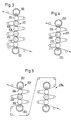
- the calender illustrated in Fig. 1 has one Roll stack 1, which consists of twelve rolls, namely an upper roller 2 and a lower roller 3, both are designed as a deflection compensation roller, and ten intermediate rolls arranged between them.
- a heatable hard from top to bottom Roller 4 is an elastic roller 5, a heatable hard one Roller 6, an elastic roller 7, a heatable hard Roller 8, two elastic rollers 9 and 10, a driven, heated hard roller 11, an elastic Roller 12 and a heated hard roller 13.
- the elastic Rollers 5, 7, 9, 10 and 12 each have a cover 14 made of elastic plastic.
- the jacket 15 the upper roller 2 and the jacket 15a of the lower roller 3 consist essentially entirely of elastic Plastic or wear a cover 27a from such elastic plastic (Fig. 2), so that the top roller 2 and lower roller 3 act as elastic rollers. Therefore, between the elastic rollers 9 and 10 Alternating gap 16 formed. All other columns are working columns 17, each by an elastic roller and a hard roller are limited.
- a paper web 18 is either fed directly from a paper machine or fed from an unwinder 19, passes under the guidance of idlers 20 first six working column 17, then the alternating gap 16 and finally four other working columns 17, whereupon it is wound up in a winder 21 becomes.
- the paper web lies in the six upper working columns 18 with one side, in the four lower ones Working columns with the other side on the elastic Rolls on, so that the desired surface structure on both sides, for example gloss or smoothness becomes.
- the upper roll has a carrier 22 which is held in the stand 23 of the calender in a rotationally fixed manner and can be loaded by a force 24.
- the jacket 15 of the top roller 2 is supported on this carrier 22 with the aid of closely adjacent hydrostatic support elements 25.
- Each support member 25 - or pair of support members 25 - is pressurized by an individual control line 26.
- the roll shell 15 is formed by a carrier 27 in the form of an inner tube 27 made of lamellar graphite cast, which carries an outer cover 27a made of elastic plastic, which has a higher wear resistance than this cast.
- a material is preferred that can withstand an average compressive stress of more than 45 N / mm 2 , preferably up to 60 N / mm 2, and has a low marking sensitivity.
- An example is an epoxy resin reinforced by fibers, in particular carbon fibers, such as the reference material "TopTec 4" already mentioned.
- the carrier 27 forming the roll shell 15 has a substantially smaller wall thickness than a chilled cast iron shell which has the same inside diameter. Compared to chilled cast iron jackets that have a thickness of 80 to 145 mm, only 45 to 70 mm and a wall thickness of the plastic cover 27a in the range of 8 to 15 mm, preferably 10 mm, are required for lamellar or spheroidal graphite cast iron jackets.
- channels 28 running near the surface are provided, to which superheated steam at elevated pressure is supplied via control lines 29, for example at a temperature of 220 ° C., which corresponds to a pressure of 22 bar and to a surface temperature of approximately 150 ° C. leads.
- the stack 101 shows a calender with a stack 101, which consists of eight rollers.
- the elastic rollers are marked by hatching.
- the stack 101 therefore includes an upper roller 102 and a lower roller 103 and in between a heatable hard roller 104, an elastic roller 105, a heated hard roller 106, two elastic rollers 109 and 110 and a heated hard roller 111.
- FIG. 4 is a calender with a stack 201 from illustrates six rollers, namely an upper roller 202 and a lower roller 203 and in between one heatable hard roller 204, two elastic rollers 209 and 210 and a heatable hard roller 211.
- this smaller number of rollers in the stack is sufficient to produce paper with a high surface quality on both sides. This applies in particular if at least in the lowest working gap with compressive stresses above 42 N / mm 2 , preferably between 45 and 60 N / mm 2 , and on the surfaces of the heated rolls with temperatures above 100 ° C, preferably between 130 and 160 ° C, is worked.
- the stack 301 has an upper roller 302 and a lower roller 303 and in between a heatable hard roller 304, an elastic one Roller 305 and a heated hard roller 306 on.
- the stack 301a has the same structure. However the paper web is guided so that it is in the first stack with one side and in the second stack with the other Side rests on the elastic rollers and therefore is satined on both sides.
- the roll stack 1 of the 12-roll calender of FIG. 1 has five heatable hard rollers 4, 6, 8, 11, 13.
- Known 12-roll calenders on the other hand, only have four such heated rollers. As a result, it is possible Add 25% more heat energy and therefore the available deformation energy to increase accordingly. The same applies to the other calenders where one more heatable roller each or in the 2-stack calender 5 even two more heated rollers can be used.
- the desired deformability of the top roller jacket 2 and possibly the lower roller 3 should become one Deformability factor that is at least four times, but is preferably more than five times as large as with a chilled cast iron jacket. This is for example with a lamellar or spheroidal graphite jacket can be reached, which is provided with a plastic cover with a low modulus of elasticity is.
- each an even number of Reels can also show an odd stack Roll number can be applied when the bottom roll is in usually provided with a hard roll shell is.
- the illustrated ones Calender with other known means of improvement the paper treatment for example the middle rollers can be mounted on levers, about that with the help of compensation devices the influence of overhanging weights can be compensated can.
Landscapes
- Paper (AREA)
- Casting Or Compression Moulding Of Plastics Or The Like (AREA)
- Treatment Of Fiber Materials (AREA)
- Lubricants (AREA)
Claims (11)
- Calandreuse comportant au moins un empilement de cylindres qui présente comme cylindres supérieurs (2 ; 102 ; 202 ;302) et comme cylindres inférieurs (3; 103 ; 203 ; 303) chaque fois un cylindre de compensation de la flexion doté d'une enveloppe de cylindre (15 ;15a) qui s'appuie par l'intermédiaire d'éléments hydrostatiques d'appui (25) sur un support (22) monté de manière à ne pas pourvoir tourner et traversé par les éléments d'appui, et comme cylindres centraux des cylindres rigides (4, 6, 8, 11 ; 13, 104, 106, 111 ; 204, 211 ; 304, 304) et des cylindres élastiques (5, 7, 9, 10, 12 ; 105, 109, 110 ; 209, 210 ; 305), lesquels cylindres forment au moins quatre interstices de travail qui sont délimités par un cylindre rigide et par un cylindre élastique et éventuellement un interstice alterné qui est délimité par deux cylindres élastiques, l'enveloppe de cylindre (15, 15a) du cylindre supérieur (2 ; 102 ; 202, 302) et/ou du cylindre inférieur (3 ; 103 ; 203 ; 303) portent un revêtement (27a) en matière synthétique élastique, et le cylindre central chaque fois voisin (4 ; 104 ; 204 ; 304 ; 13 ; 111 ; 211 ; 306) est un cylindre rigide, caractérisée en ce que l'enveloppe de cylindre (15 ; 15a) est conçue de manière à être déformable avec un facteur de déformabilité :où
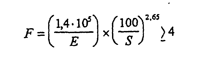 et dans ce but l'enveloppe du cylindre (15 ; 15a) est réalisée en une fonte à faible module E, comme de la fonte rigide, mais d'une résistance à l'usure insuffisante, et le revêtement (27a) en matière synthétique élastique sert de couche de protection contre l'usure.E = module E de l'enveloppe du cylindre, en N/mm2 etS = épaisseur de paroi de l'enveloppe du cylindre, en mm,
 - Calandreuse selon la revendication 1, caractérisée en ce que le facteur de déformabilité > 5.
- Calandreuse selon la revendication 1 ou 2, caractérisée en ce que la matière synthétique présente une résistance à l'usure supérieure à celle du matériau d'enveloppe.
- Calandreuse selon la revendication 3, caractérisée en ce que l'enveloppe de cylindre (15; 15a) est réalisée en fonte graphitique lamellaire.
- Calandreuse selon l'une des revendications 1 à 4, caractérisée en ce que l'enveloppe de cylindre (15) est réalisée en fonte graphitique sphéroïdale et porte un revêtement (27a) en matière synthétique élastique.
- Calandreuse selon l'une des revendications 1 à 5, caractérisée en ce que la matière synthétique est une résine époxy renforcée de fibres.
- Calandreuse selon l'une des revendications 1 à 6, caractérisée en ce que le cylindre de compensation de la flexion présente une commande à quatre zones dans laquelle un liquide sous pression peut être apporté sous différentes pressions aux éléments de soutien (25), individuellement ou par paire.
- Calandreuse selon l'une des revendications 1 à 7, caractérisée en ce qu'au moins le cylindre central supérieur (4) peut être chauffé.
- Calandreuse selon l'une des revendications 1 à 8, caractérisée en ce que tous les cylindres centraux rigides (4, 6, 8, 11, 13) peuvent être chauffés.
- Calandreuse selon la revendication 8 ou 9, caractérisée en ce que le chauffage s'effectue au moyen de vapeur d'eau qui est amenée sous une surpression.
- Calandreuse selon l'une des revendications 1 à 10, caractérisée en ce que dans un empilement (1) de 12 cylindres, le 4ème cylindre (11) est entraíné par le bas.
Applications Claiming Priority (2)
| Application Number | Priority Date | Filing Date | Title |
|---|---|---|---|
| DE19521402 | 1995-06-13 | ||
| DE19521402A DE19521402C2 (de) | 1995-06-13 | 1995-06-13 | Kalander für die Behandlung einer Papierbahn |
Publications (3)
| Publication Number | Publication Date |
|---|---|
| EP0748895A2 EP0748895A2 (fr) | 1996-12-18 |
| EP0748895A3 EP0748895A3 (fr) | 1998-05-13 |
| EP0748895B1 true EP0748895B1 (fr) | 2001-05-02 |
Family
ID=7764221
Family Applications (1)
| Application Number | Title | Priority Date | Filing Date |
|---|---|---|---|
| EP96108397A Expired - Lifetime EP0748895B1 (fr) | 1995-06-13 | 1996-05-28 | Calendre |
Country Status (8)
| Country | Link |
|---|---|
| US (1) | US5755156A (fr) |
| EP (1) | EP0748895B1 (fr) |
| JP (1) | JP2665215B2 (fr) |
| KR (1) | KR0170075B1 (fr) |
| AT (1) | ATE200920T1 (fr) |
| CA (1) | CA2176778C (fr) |
| DE (2) | DE19521402C2 (fr) |
| EA (1) | EA000188B1 (fr) |
Families Citing this family (9)
| Publication number | Priority date | Publication date | Assignee | Title |
|---|---|---|---|---|
| DE19633671C2 (de) † | 1996-08-21 | 1999-03-11 | Voith Sulzer Finishing Gmbh | Kalander |
| DE19758443A1 (de) † | 1997-03-14 | 1998-09-24 | Voith Sulzer Finishing Gmbh | Glättwerk |
| DE19811474A1 (de) * | 1998-03-17 | 1999-09-23 | Kuesters Eduard Maschf | Kalanderanordnung |
| DE19813640A1 (de) | 1998-03-27 | 1999-09-30 | Voith Sulzer Papiertech Patent | Kalander, insbesondere zur Behandlung einer Papierbahn |
| DE19828722C2 (de) * | 1998-06-29 | 2001-06-21 | Schwaebische Huettenwerke Gmbh | Walzengruppe |
| DE19832064C2 (de) * | 1998-07-16 | 2000-09-07 | Voith Sulzer Papiertech Patent | Kalander für Bahnen aus Papier oder ähnlichem Material |
| DE19832067B4 (de) * | 1998-07-16 | 2005-04-21 | Voith Paper Patent Gmbh | Kalander für Bahnen aus Papier oder ähnlichem Material |
| DE10164344C1 (de) * | 2001-12-28 | 2003-06-18 | Schwaebische Huettenwerke Gmbh | Formstabilisierter Walzenkörper |
| JP2007056409A (ja) * | 2005-08-25 | 2007-03-08 | Nippon Paper Industries Co Ltd | スーパーカレンダー |
Family Cites Families (14)
| Publication number | Priority date | Publication date | Assignee | Title |
|---|---|---|---|---|
| US2300994A (en) * | 1938-08-09 | 1942-11-03 | Cons Water Power & Paper Co | Calender for paper |
| DE1193792B (de) * | 1961-06-30 | 1965-05-26 | Textilmaschinen Eduard Kuester | Walze fuer die Druckbehandlung von Warenbahnen |
| JPS49339B1 (fr) * | 1964-09-22 | 1974-01-07 | ||
| AT369063B (de) * | 1979-05-10 | 1982-12-10 | Escher Wyss Ag | Walzvorrichtung zum walzen von bahnfoermigen materialien |
| DE3020669C2 (de) * | 1980-05-30 | 1984-02-16 | Küsters, Eduard, 4150 Krefeld | Verfahren zur Steuerung der Liniendruckverteilung in einem Kalander sowie ensprechender Kalander |
| DE3131799C2 (de) * | 1981-08-12 | 1984-08-30 | Kleinewefers Gmbh, 4150 Krefeld | Walzenpresse für Papier- und ähnliche Bahnen, insbesondere Kalander |
| DE3201635C2 (de) * | 1982-01-20 | 1984-02-16 | Küsters, Eduard, 4150 Krefeld | Kalanderanordnung |
| DE3767476D1 (de) * | 1987-05-09 | 1991-02-21 | Kleinewefers Gmbh | Verfahren zum betrieb einer walzenmaschine und steueranordnung zur durchfuehrung dieses verfahrens. |
| DE3735438C1 (de) * | 1987-10-20 | 1989-05-18 | Kleinewefers Gmbh | Verfahren zum Betrieb eines Kalanders und Kalander zur Durchfuehrung dieses Verfahrens |
| FI82102C (fi) * | 1987-12-11 | 1994-01-26 | Valmet Paper Machinery Inc | Valssystem i superkalander. valssystem i superkalander |
| FI88420B (fi) * | 1991-03-20 | 1993-01-29 | Valmet Paper Machinery Inc | Foerfarande foer framstaellning av en vals och en vals |
| CH682893A5 (de) * | 1991-05-03 | 1993-12-15 | Escher Wyss Ag | Walze und Kunststoffolien-Giessanlage mit einer Walze. |
| DE9314568U1 (de) * | 1993-09-27 | 1995-02-02 | Eduard Küsters Maschinenfabrik GmbH & Co KG, 47805 Krefeld | Walze |
| FI96334C (fi) * | 1993-11-24 | 1996-06-10 | Valmet Paper Machinery Inc | Menetelmä paperin tai vastaavan rainamateriaalin kalanteroinnissa ja menetelmää soveltava kalanteri |
-
1995
- 1995-06-13 DE DE19521402A patent/DE19521402C2/de not_active Expired - Fee Related
-
1996
- 1996-05-16 CA CA002176778A patent/CA2176778C/fr not_active Expired - Fee Related
- 1996-05-28 AT AT96108397T patent/ATE200920T1/de not_active IP Right Cessation
- 1996-05-28 DE DE59606842T patent/DE59606842D1/de not_active Expired - Fee Related
- 1996-05-28 EP EP96108397A patent/EP0748895B1/fr not_active Expired - Lifetime
- 1996-06-04 KR KR1019960019724A patent/KR0170075B1/ko not_active Expired - Fee Related
- 1996-06-13 EA EA199600030A patent/EA000188B1/ru not_active IP Right Cessation
- 1996-06-13 JP JP8152163A patent/JP2665215B2/ja not_active Expired - Fee Related
-
1997
- 1997-05-05 US US08/850,283 patent/US5755156A/en not_active Expired - Fee Related
Also Published As
| Publication number | Publication date |
|---|---|
| DE19521402C1 (de) | 1996-07-04 |
| DE19521402C2 (de) | 2002-02-07 |
| CA2176778C (fr) | 1999-09-14 |
| CA2176778A1 (fr) | 1996-12-14 |
| KR970001734A (ko) | 1997-01-24 |
| EA199600030A3 (ru) | 1997-03-31 |
| JPH093791A (ja) | 1997-01-07 |
| EP0748895A2 (fr) | 1996-12-18 |
| JP2665215B2 (ja) | 1997-10-22 |
| EP0748895A3 (fr) | 1998-05-13 |
| EA199600030A2 (ru) | 1996-12-30 |
| EA000188B1 (ru) | 1998-12-24 |
| US5755156A (en) | 1998-05-26 |
| KR0170075B1 (ko) | 1999-03-30 |
| DE59606842D1 (de) | 2001-06-07 |
| ATE200920T1 (de) | 2001-05-15 |
Similar Documents
| Publication | Publication Date | Title |
|---|---|---|
| EP0732446B1 (fr) | Calandre pour le traitement d'une bande de papier sur deux faces | |
| EP0735185B1 (fr) | Calandre pour le traitement des deux surfaces d'une bande de papier | |
| DE69431492T2 (de) | Kalender zum Kalandrieren einer Papierbahn | |
| DE3131799C2 (de) | Walzenpresse für Papier- und ähnliche Bahnen, insbesondere Kalander | |
| DE3516535C2 (fr) | ||
| DE3735438C1 (de) | Verfahren zum Betrieb eines Kalanders und Kalander zur Durchfuehrung dieses Verfahrens | |
| EP0732445B2 (fr) | Calandre pour le traitement d'une bande de papier | |
| EP0748895B1 (fr) | Calendre | |
| EP0732447B2 (fr) | Calandre pour le traitement d'une bande de papier sur deux faces | |
| DE60026717T2 (de) | Kalander mit zwei durchbiegungseinstellzwischenwalzen | |
| EP0972878A2 (fr) | Calandre pour bandes de papier ou analogue | |
| DE19508352B4 (de) | Kalander für die Behandlung einer Papierbahn | |
| DE19508349C2 (de) | Kalander für die Behandlung einer Papierbahn und Verfahren zu dessen Betrieb | |
| EP0933472B1 (fr) | Procédé de fonctionnement d'une calandre et calandre | |
| DE19534911C2 (de) | Kalander für die Behandlung einer Papierbahn | |
| EP0799933B1 (fr) | Calandre pour papier ou similaire | |
| EP0928844A2 (fr) | Calandre à papier et son procédé d' opération | |
| DE60217135T2 (de) | Kalander | |
| DE102006017460B4 (de) | Beheizbare Kalanderwalze | |
| DE102008040247A1 (de) | Bandkalender |
Legal Events
| Date | Code | Title | Description |
|---|---|---|---|
| PUAI | Public reference made under article 153(3) epc to a published international application that has entered the european phase |
Free format text: ORIGINAL CODE: 0009012 |
|
| AK | Designated contracting states |
Kind code of ref document: A2 Designated state(s): AT BE DE FI FR GB IT NL SE |
|
| PUAL | Search report despatched |
Free format text: ORIGINAL CODE: 0009013 |
|
| AK | Designated contracting states |
Kind code of ref document: A3 Designated state(s): AT BE DE FI FR GB IT NL SE |
|
| 17P | Request for examination filed |
Effective date: 19980422 |
|
| 17Q | First examination report despatched |
Effective date: 20000323 |
|
| GRAG | Despatch of communication of intention to grant |
Free format text: ORIGINAL CODE: EPIDOS AGRA |
|
| GRAG | Despatch of communication of intention to grant |
Free format text: ORIGINAL CODE: EPIDOS AGRA |
|
| GRAH | Despatch of communication of intention to grant a patent |
Free format text: ORIGINAL CODE: EPIDOS IGRA |
|
| GRAH | Despatch of communication of intention to grant a patent |
Free format text: ORIGINAL CODE: EPIDOS IGRA |
|
| RAP1 | Party data changed (applicant data changed or rights of an application transferred) |
Owner name: VOITH PAPER GMBH |
|
| RAP1 | Party data changed (applicant data changed or rights of an application transferred) |
Owner name: VOITH PAPER PATENT GMBH |
|
| GRAA | (expected) grant |
Free format text: ORIGINAL CODE: 0009210 |
|
| AK | Designated contracting states |
Kind code of ref document: B1 Designated state(s): AT BE DE FI FR GB IT NL SE |
|
| REF | Corresponds to: |
Ref document number: 200920 Country of ref document: AT Date of ref document: 20010515 Kind code of ref document: T |
|
| ITF | It: translation for a ep patent filed | ||
| GBT | Gb: translation of ep patent filed (gb section 77(6)(a)/1977) |
Effective date: 20010508 |
|
| ET | Fr: translation filed | ||
| REF | Corresponds to: |
Ref document number: 59606842 Country of ref document: DE Date of ref document: 20010607 |
|
| REG | Reference to a national code |
Ref country code: GB Ref legal event code: IF02 |
|
| PLBE | No opposition filed within time limit |
Free format text: ORIGINAL CODE: 0009261 |
|
| STAA | Information on the status of an ep patent application or granted ep patent |
Free format text: STATUS: NO OPPOSITION FILED WITHIN TIME LIMIT |
|
| 26N | No opposition filed | ||
| PGFP | Annual fee paid to national office [announced via postgrant information from national office to epo] |
Ref country code: GB Payment date: 20030422 Year of fee payment: 8 |
|
| PGFP | Annual fee paid to national office [announced via postgrant information from national office to epo] |
Ref country code: FR Payment date: 20030522 Year of fee payment: 8 |
|
| PGFP | Annual fee paid to national office [announced via postgrant information from national office to epo] |
Ref country code: AT Payment date: 20030523 Year of fee payment: 8 |
|
| PGFP | Annual fee paid to national office [announced via postgrant information from national office to epo] |
Ref country code: BE Payment date: 20030526 Year of fee payment: 8 |
|
| PGFP | Annual fee paid to national office [announced via postgrant information from national office to epo] |
Ref country code: NL Payment date: 20030528 Year of fee payment: 8 |
|
| PG25 | Lapsed in a contracting state [announced via postgrant information from national office to epo] |
Ref country code: GB Free format text: LAPSE BECAUSE OF NON-PAYMENT OF DUE FEES Effective date: 20040528 Ref country code: AT Free format text: LAPSE BECAUSE OF NON-PAYMENT OF DUE FEES Effective date: 20040528 |
|
| PG25 | Lapsed in a contracting state [announced via postgrant information from national office to epo] |
Ref country code: BE Free format text: LAPSE BECAUSE OF NON-PAYMENT OF DUE FEES Effective date: 20040531 |
|
| BERE | Be: lapsed |
Owner name: *VOITH PAPER PATENT G.M.B.H. Effective date: 20040531 |
|
| PG25 | Lapsed in a contracting state [announced via postgrant information from national office to epo] |
Ref country code: NL Free format text: LAPSE BECAUSE OF NON-PAYMENT OF DUE FEES Effective date: 20041201 |
|
| GBPC | Gb: european patent ceased through non-payment of renewal fee | ||
| PG25 | Lapsed in a contracting state [announced via postgrant information from national office to epo] |
Ref country code: FR Free format text: LAPSE BECAUSE OF NON-PAYMENT OF DUE FEES Effective date: 20050131 |
|
| NLV4 | Nl: lapsed or anulled due to non-payment of the annual fee |
Effective date: 20041201 |
|
| REG | Reference to a national code |
Ref country code: FR Ref legal event code: ST |
|
| PGFP | Annual fee paid to national office [announced via postgrant information from national office to epo] |
Ref country code: SE Payment date: 20050512 Year of fee payment: 10 |
|
| PG25 | Lapsed in a contracting state [announced via postgrant information from national office to epo] |
Ref country code: IT Free format text: LAPSE BECAUSE OF NON-PAYMENT OF DUE FEES;WARNING: LAPSES OF ITALIAN PATENTS WITH EFFECTIVE DATE BEFORE 2007 MAY HAVE OCCURRED AT ANY TIME BEFORE 2007. THE CORRECT EFFECTIVE DATE MAY BE DIFFERENT FROM THE ONE RECORDED. Effective date: 20050528 |
|
| PG25 | Lapsed in a contracting state [announced via postgrant information from national office to epo] |
Ref country code: SE Free format text: LAPSE BECAUSE OF NON-PAYMENT OF DUE FEES Effective date: 20060529 |
|
| EUG | Se: european patent has lapsed | ||
| PGFP | Annual fee paid to national office [announced via postgrant information from national office to epo] |
Ref country code: FI Payment date: 20070514 Year of fee payment: 12 |
|
| PGFP | Annual fee paid to national office [announced via postgrant information from national office to epo] |
Ref country code: DE Payment date: 20070522 Year of fee payment: 12 |
|
| PG25 | Lapsed in a contracting state [announced via postgrant information from national office to epo] |
Ref country code: FI Free format text: LAPSE BECAUSE OF NON-PAYMENT OF DUE FEES Effective date: 20080528 |
|
| PG25 | Lapsed in a contracting state [announced via postgrant information from national office to epo] |
Ref country code: DE Free format text: LAPSE BECAUSE OF NON-PAYMENT OF DUE FEES Effective date: 20081202 |