EP0748141A2 - Überlastregelungssystem und -methode für Paketvermittlungsnetzwerke mit max-min-Fairness - Google Patents
Überlastregelungssystem und -methode für Paketvermittlungsnetzwerke mit max-min-Fairness Download PDFInfo
- Publication number
- EP0748141A2 EP0748141A2 EP96304020A EP96304020A EP0748141A2 EP 0748141 A2 EP0748141 A2 EP 0748141A2 EP 96304020 A EP96304020 A EP 96304020A EP 96304020 A EP96304020 A EP 96304020A EP 0748141 A2 EP0748141 A2 EP 0748141A2
- Authority
- EP
- European Patent Office
- Prior art keywords
- allocation
- source
- rate
- algorithm
- congestion control
- Prior art date
- Legal status (The legal status is an assumption and is not a legal conclusion. Google has not performed a legal analysis and makes no representation as to the accuracy of the status listed.)
- Withdrawn
Links
Images





Classifications
-
- H—ELECTRICITY
- H04—ELECTRIC COMMUNICATION TECHNIQUE
- H04L—TRANSMISSION OF DIGITAL INFORMATION, e.g. TELEGRAPHIC COMMUNICATION
- H04L49/00—Packet switching elements
- H04L49/30—Peripheral units, e.g. input or output ports
- H04L49/3081—ATM peripheral units, e.g. policing, insertion or extraction
-
- H—ELECTRICITY
- H04—ELECTRIC COMMUNICATION TECHNIQUE
- H04L—TRANSMISSION OF DIGITAL INFORMATION, e.g. TELEGRAPHIC COMMUNICATION
- H04L49/00—Packet switching elements
- H04L49/50—Overload detection or protection within a single switching element
- H04L49/501—Overload detection
- H04L49/503—Policing
-
- H—ELECTRICITY
- H04—ELECTRIC COMMUNICATION TECHNIQUE
- H04L—TRANSMISSION OF DIGITAL INFORMATION, e.g. TELEGRAPHIC COMMUNICATION
- H04L49/00—Packet switching elements
- H04L49/50—Overload detection or protection within a single switching element
- H04L49/505—Corrective measures
- H04L49/506—Backpressure
-
- H—ELECTRICITY
- H04—ELECTRIC COMMUNICATION TECHNIQUE
- H04Q—SELECTING
- H04Q11/00—Selecting arrangements for multiplex systems
- H04Q11/04—Selecting arrangements for multiplex systems for time-division multiplexing
- H04Q11/0428—Integrated services digital network, i.e. systems for transmission of different types of digitised signals, e.g. speech, data, telecentral, television signals
- H04Q11/0478—Provisions for broadband connections
-
- H—ELECTRICITY
- H04—ELECTRIC COMMUNICATION TECHNIQUE
- H04L—TRANSMISSION OF DIGITAL INFORMATION, e.g. TELEGRAPHIC COMMUNICATION
- H04L12/00—Data switching networks
- H04L12/54—Store-and-forward switching systems
- H04L12/56—Packet switching systems
- H04L12/5601—Transfer mode dependent, e.g. ATM
- H04L2012/5619—Network Node Interface, e.g. tandem connections, transit switching
-
- H—ELECTRICITY
- H04—ELECTRIC COMMUNICATION TECHNIQUE
- H04L—TRANSMISSION OF DIGITAL INFORMATION, e.g. TELEGRAPHIC COMMUNICATION
- H04L12/00—Data switching networks
- H04L12/54—Store-and-forward switching systems
- H04L12/56—Packet switching systems
- H04L12/5601—Transfer mode dependent, e.g. ATM
- H04L2012/5629—Admission control
- H04L2012/5631—Resource management and allocation
- H04L2012/5636—Monitoring or policing, e.g. compliance with allocated rate, corrective actions
-
- H—ELECTRICITY
- H04—ELECTRIC COMMUNICATION TECHNIQUE
- H04L—TRANSMISSION OF DIGITAL INFORMATION, e.g. TELEGRAPHIC COMMUNICATION
- H04L49/00—Packet switching elements
- H04L49/10—Packet switching elements characterised by the switching fabric construction
- H04L49/103—Packet switching elements characterised by the switching fabric construction using a shared central buffer; using a shared memory
-
- H—ELECTRICITY
- H04—ELECTRIC COMMUNICATION TECHNIQUE
- H04L—TRANSMISSION OF DIGITAL INFORMATION, e.g. TELEGRAPHIC COMMUNICATION
- H04L49/00—Packet switching elements
- H04L49/20—Support for services
- H04L49/201—Multicast operation; Broadcast operation
-
- H—ELECTRICITY
- H04—ELECTRIC COMMUNICATION TECHNIQUE
- H04L—TRANSMISSION OF DIGITAL INFORMATION, e.g. TELEGRAPHIC COMMUNICATION
- H04L49/00—Packet switching elements
- H04L49/20—Support for services
- H04L49/205—Quality of Service based
-
- H—ELECTRICITY
- H04—ELECTRIC COMMUNICATION TECHNIQUE
- H04L—TRANSMISSION OF DIGITAL INFORMATION, e.g. TELEGRAPHIC COMMUNICATION
- H04L49/00—Packet switching elements
- H04L49/30—Peripheral units, e.g. input or output ports
- H04L49/3018—Input queuing
-
- H—ELECTRICITY
- H04—ELECTRIC COMMUNICATION TECHNIQUE
- H04L—TRANSMISSION OF DIGITAL INFORMATION, e.g. TELEGRAPHIC COMMUNICATION
- H04L49/00—Packet switching elements
- H04L49/30—Peripheral units, e.g. input or output ports
- H04L49/3027—Output queuing
Definitions
- This application is related to congestion control systems for communications networks and more particularly to an efficient method for carrying out such congestion control in packet-switched networks providing fairness.
- ATM Asynchronous Transfer Mode
- Broadband packet networks based on Asynchronous Transfer Mode are enabling the integration of traffic with a wide range of characteristics within a single communication network.
- all communication at the ATM layer is in terms of fixed-size packets, called "cells" in ATM terminology.
- An ATM cell consists of 48 bytes of payload and 5 bytes for the ATM-layer header. Routing of cells is accomplished through packet switches over virtual circuits set up between endpoints.
- ATM is capable of handling multiple classes of traffic ranging from real-time video to best-effort traffic requiring no quality-of-service guarantees.
- CBR Constant Bit Rate
- VBR Variable Bit Rate
- URR Unspecified Bit Rate
- ABR vailable Bit Rate
- the ABR service category corresponds to "best-effort" traffic which is the focus for a preferred embodiment of the system and method of our invention.
- a primary motivation for development of the ABR service category was the economical support of data traffic where each packet of data is segmented into ATM cells.
- Such "best-effort" traffic will generally be characterized as having no real-time deadlines and requiring weak guarantees on the available bandwidth, delay, or cell loss rate.
- This "best-effort" mode is similar in nature to the service provided by the current Internet (generally using the Transmission Control Protocol (TCP) or User Datagram Protocol (UDP)), except that connections still need to be set up at the ATM layer over virtual circuits between endpoints, either explicitly or implicitly.
- TCP Transmission Control Protocol
- UDP User Datagram Protocol
- ATM raises new opportunities for implementing congestion control at a lower layer, providing the potential for improving the performance of TCP even above that obtained in today's datagram networks.
- the higher speed and possibly better congestion control algorithms which may arise with ATM's ABR service offer promise even for protocols designed for today's datagram service.
- the fixed size of ATM cells simplifies the implementation of the switching function in many cases, thus enabling ATM networks to scale up to high speeds.
- rate-based flow control Control of the cell rate for a connection would occur at least at the transmission source, which would shape the connection's traffic as directed by feedback from the network. Optionally, such control may occur at points within the network as well. Under a rate-based framework, the share of bandwidth allocated to a connection is not supposed to depend on the delays between points where data is shaped on a per-connection basis.
- the rate-based congestion control approach has the potential to provide close-to-ideal throughput with a fraction of the buffering required by link-level flow control, especially for wide area networks.
- the source of each connection periodically transmits a special resource management (RM) cell.
- the RM cell specifies the bandwidth requested by the connection.
- Each switch on the path of the RM cell may modify the request based on the bandwidth it is able to allocate to the connection on its outbound link.
- the RM cell having had its bandwidth request reduced by any switch unable to allocate the requested bandwidth, is returned to the source, which will then set its rate based on that of the bottleneck link in the path of the connection.
- the rate-based approach requires an algorithm for fair allocation of bandwidth among the connections sharing a common output link of a switch.
- the algorithm On receipt of an RM cell from a connection (or, in the general case, a packet containing comparable information), the algorithm is invoked to determine the current bandwidth allocation of the connection on the output link, taking into account the available bandwidth and the current allocations of other connections.
- Charny A. Charny, "An Algorithm for Rate Allocation in a Packet-Switching Network with Feedback," M.S. Thesis, MIT, Dept. of Electrical and Computer Science, Cambridge, MA, 1994, hereafter cited as Charny 94).
- a congestion control method for communications networks operating to cause a data source to periodically inject into a data flow from that source a first indicator representative of a rate at which the source is currently transmitting data to the network and a second indicator representative of a rate at which the source is desirous of transmitting data.
- the method of the invention determines an allocation according to a predetermined criterion for bandwidth to be apportioned among competing data flows at switches within the network and operates on the second indicator sent by the source at successive switches in a transmission path in that network between the source and a destination to compare the rate represented by that second indicator with a maximum rate allocation determined by each switch. Where the rate represented by that second indicator is greater than that maximum rate allocation the invention causes the rate representation in that second indicator to be changed to that maximum rate allocation.
- the method of the invention causes those first and said second indicators to be returned to the source, whereby any modification of the rate represented by that second indicator by any of the traversed switches operates to establish a maximum data transmission rate for that source.
- Figure 1 depicts an exemplary network configuration for implementing the system of the invention.
- Figure 2 depicts the required fields for the congestion control information packet associated with the method of the invention.
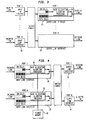
- Figure 3 shows a specific implementation of the congestion control method of the invention in an output buffered switch.
- Figure 4 provides a specific implementation of the congestion control method of the invention in an input buffered switch.
- FIGS 5A and 5B depicts the steps of the rate allocation method of the invention in flow chart form.
- Figure 6 presents the pseudo-code for the rate allocation algorithm of the invention.
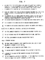
- Figure 7 provides a listing of definitions and notations for the algorithm pseudo-code of Figure 6.
- Figure 8 presents the pseudo-code executed when a new connection opens in a switch carrying out the method of the invention.
- Figure 9 presents the pseudo-code executed when a connection closes in a switch carrying out the method of the invention.
- Figure 10 depicts another exemplary network configuration for implementation of the congestion control method of the invention.
- Figure 11 provides a graphical presentation of a first set of simulation results.
- Figure 12 provides a graphical presentation of a second set of simulation results.
- Figure 13 provides a graphical presentation of a third set of simulation results.
- processors For clarity of explanation, the illustrative embodiment of the present invention is presented as comprising individual functional blocks (including functional blocks labeled as "processors"). The functions these blocks represent may be provided through the use of either shared or dedicated hardware, including, but not limited to, hardware capable of executing software. For example the functions of processors presented in Figures 3 and 4 may be provided by a single shared processor. (Use of the term "processor” should not be construed to refer exclusively to hardware capable of executing software.)
- Illustrative embodiments may comprise microprocessor and/or digital signal processor (DSP) hardware, such as the AT&T DSP16 or DSP32C, read-only memory (ROM) for storing software performing the operations discussed below, and random access memory (RAM) for storing results.
- DSP digital signal processor
- ROM read-only memory
- RAM random access memory
- VLSI Very large scale integration
- the congestion control method of the invention is implemented within a communications network.
- a simplified, but nonetheless illustrative such network is shown in Figure 1.
- the network is seen to comprise four switches (Nos. 1, 2, 3 & 4) connected in tandem to provide a network for interconnecting various host computers depicted as either a source or a destination for communications traffic transmitted across the network.
- a communications path from Source S 2 to Destination D 2 would traverse the path from an input port for Switch 2, through that switch and out at an output port therefrom, thence over a transmission line connecting Switches 2 and 3 and into an input port of Switch 3. After being switched to an appropriate output port by Switch 3, the path would continue from that output port to Destination D 2 .
- the congestion control method of the invention is connection oriented, we choose, in a preferred embodiment, to illustrate the implementation of virtual circuits in the network of Figure 1. * / With that virtual circuit implementation of our preferred embodiment, all of the packets belonging to a particular virtual circuit will traverse the same path through the network from source to destination. * / It should be understood, however, that the network could be implemented as a connectionless, or datagram network and the method of the invention would still operate, albeit with some degradation of performance levels. By having a switch maintain state on a source-destination basis, we could come close to the described here. The identity of a connection would be based on a mapping of the source-destination addresses to a unique identity.
- the rate of transmission of packets belonging to each virtual circuit is controlled individually by the source of the virtual circuit, based on a feedback mechanism.
- the source periodically transmits congestion control information.
- Such information may be transmitted as separate packets or may be piggy-backed onto data packets.
- congestion control information is transmitted via separate packets, and in the particular context of ATM technology, those separate packets are designated as resource management (RM) cells.
- RM resource management
- all of the processing required for bandwidth allocation according to the method of the invention is performed when an RM cell travelling in the forward direction is received at a switch. In this embodiment, no processing is performed by the switches on an RM cell traveling backward to the source, although it will be apparent that the forward direction processing of the preferred embodiment could readily be implemented in the rearward direction.
- the rate allocation algorithm of our invention is applied to each switch of the network independently.
- separate instances of the algorithm are executed at each output port of the switch (or input port in the case of an input buffered switch) to control the allocation of bandwidth among the connections sharing the corresponding outgoing link.
- the allocation may be performed by a central processor in the switch which is responsible for managing each one of the outgoing links.
- Figure 2 depicts the required fields for the congestion control information packet associated with the method of the invention.
- the specific designators shown in that figure for those fields correspond to designations adopted by the ATM Forum for the fields of an RM cell.
- the Explicit Rate (ER) field is set by the source of the virtual circuit connection to the amount of bandwidth it requests.
- the rate allocation algorithm of our invention operating in a switch on the path of the connection may modify this field as the RM cell passes through the switch, by reducing the value thereof to the maximum amount of bandwidth it is able to allocate to the connection on the outgoing link, if such maximum amount is less than the value in the ER field of the received RM cell.
- the CCR field is set by the source of the connection and is not modified by the switches. This field indicates the current transmission rate of the source. It is assumed that the source would set the CCR field based on the ER value in the RM cell that was returned by the network most recently. The latter value represents the bandwidth available at the bottleneck link in the network at the time the most recent RM cell traversed it. Note also that the congestion control information packet needs to specify the virtual circuit it belongs to (although this could be part of the normal packet header) and the direction of the packet (forward/backward) -- to facilitate the performance of the rate allocation algorithm as the packet passes through the switch in one direction, and the passage through the switch without processing as it travels in the reverse direction.
- FIG. 3 we show a specific implementation of the congestion control method of the invention in an output buffered switch -- i.e., a switch having its buffering and congestion control processing at its output ports.
- this exemplary switch has a plurality of input ports (illustratively I to N) interfaced to the incoming links by Input Link Interface modules 10, and a plurality of output ports (illustratively also 1 to N) interfaced to the outgoing links by a corresponding plurality of Output Link Interface modules 20.
- Each of the Output Link Interface modules provides buffering and processing functionality for buffering data for connections traversing the link and, potentially, for separating the RM cells associated with a connection from data cells for that connection.
- Such separated RM cells are then fed to Rate Allocation Algorithm Processor 30 for processing in accordance with the algorithm of our invention. After such processing of the RM cells, they are then recombined with the data cells for the associated connection by the Output Link Interface module, such that the relative order of transmission of packets within each virtual circuit is maintained. ** / ** / Although we illustrate the case of separation and recombination of RM cells, it should be understood that our invention does not preclude the processing of an RM cell without such separation and recombination. Such a non-separation practice does, however, require a relatively fast processor.
- each of the plurality of Output Link Interface modules will be configured to include Rate Allocation Algorithm Processor 30 in the same manner as depicted for the Output Link Interface module associated with Port 1, and will carry out the same buffering and processing functions described above for that illustrative Output Link Interface module.
- Figure 4 provides a specific implementation of the congestion control method of the invention in an input buffered switch -- i.e., a switch having its buffering and congestion control processing at its input ports.
- Output Link Interface modules 15 correspond functionally to the Input Link Interface modules 10 of Figure 3
- Input Link Interface modules 25, along with Rate Allocation Algorithm Processors 35 correspond essentially to Output Link Interface modules 20 and Rate Allocation Algorithm Processors 30 of Figure 3.
- the packets arriving at an input port of the switch may be destined to any of the output ports, it is not possible to run separate instances of the rate allocation algorithm independently at each input port.
- each Input Link Interface can perform allocations for any of the outgoing links.
- the collective algorithm instances maintain all of the shared allocation parameters in a common shared memory 45 to achieve this result. Synchronization among the multiple algorithm instances can be performed by the use of well known methods for locking accesses to shared variables during execution of the algorithm instances.
- the congestion control method of our invention will also be applicable to multicast virtual circuits -- i.e., a common source transmitting to multiple destinations.
- multicast virtual circuits i.e., a common source transmitting to multiple destinations.
- a transmission from Source S 3 to Destinations D 2 and D 3 since the path from S 3 to D 2 only traverses one switch (Sw. 2) while the path from S 3 to D 3 traverses two switches (Sw. 2 and Sw. 3), Sw. 3 may represent a bottleneck, or bandwidth limitation, for the S 3 to D 3 path which did not exist in the S 3 to D 2 path.
- the allocation to each one of the RM cells of the multicast flows of a multicast connection is the minimum allocation across all of the flows of the connection.
- the process of combining the returned RM cells for the several multicast paths can be performed by well known prior art methods.
- this approach is not essential.
- each RM cell has the following fields, as depicted in Figure 2:
- the cell When the destination of a connection receives an RM cell, the cell is immediately returned to the source through a reverse path.
- the source On receipt of the RM cell, the source adjusts its rate to be within the value in the ER field, which represents the maximum fair bandwidth available to the connection on the bottleneck link.
- the CCR of subsequent RM cells will be set to reflect this new allocated rate.
- the source may request a change in its allocated rate by setting the ER field of RM cells to the desired value.
- Rate allocation within a switch must be performed according to some fairness criterion, so that the total available bandwidth on the outbound link is divided fairly among the connections sharing the link.
- a commonly used fairness criterion is max-min fairness as described in Bertsekas92. To briefly illustrate the concept of max-min fairness, Let ⁇ 1 , ⁇ 2 , ..., ⁇ N be the requests of individual connections sharing a link and A 1 , A 2 , ..., A N be the allocation produced by the rate allocation algorithm.
- the allocation is max-min fair, when a request is either completely satisfied, or receives an allocation equal to the maximum among all connections. That is, those bandwidth requests that are not completely satisfied by the allocation receive equal shares of the output bandwidth.
- the sum of the A i s is should equal the total bandwidth available if there is at least one connection with A i ⁇ ⁇ i .
- a principal facet of our invention is a new rate allocation algorithm, which will be disclosed in detail hereafter, having an execution time of order one -- ⁇ ( l ). Because the execution time of our algorithm is independent of the number of virtual channels sharing the output link, the algorithm is particularly advantageous for implementation in ATM switches carrying a large number of virtual channels. Moreover, when the total available capacity or the requests of the individual connections change, the algorithm quickly converges to the max-min allocation.
- the worst-case convergence time is ⁇ ( M ( 2 D + 1 R ) ) , where D is the round-trip delay, M is the number of distinct values in the max-min allocation, and R is the rate at which resource-management (RM) cells are transmitted by each source.
- Kalampoukas95 Proof of this convergence quality is provided in a paper authored by the inventors to be published contemporaneously with the filing of this application -- see L. Kalampoukas, A. Varma and K.K. Ramakrishnan, "An Efficient Rate Allocation Algorithm for Packet-Switched Networks Providing Max-Min Fairness," 1995, [Manuscript in preparation], hereafter cited as Kalampoukas95.
- Our algorithm is asynchronous and distributed in nature. It does not require cooperation of all the switches in the network, and it can be applied in a network with varying link speeds. As previously implied, the algorithm makes use of special RM cells in the manner of Charny94. It is robust in that it can operate even if some of these special cells are lost or if the bandwidth available to the best-effort traffic is not constant. Algorithmically, its complexity is ⁇ (1).
- the packet (or cell) format used in the bandwidth allocation methodology of our invention differs from that in the scheme of Charny94. Specifically, the methodology of our invention requires an additional arithmetic value to be carried by the RM cell instead of just another bit -- to wit, the u-bit utilized in the approach of Charny94. While our rate allocation algorithm could operate with the packet format described in Charny94, we chose a different (and slightly more complex) format because it simplifies the operation of the algorithm while at the same time providing lower upper bounds to the convergence time of the algorithm.
- each switch on its path will receive the virtual circuit identifier of the connection as part of the connection setup process.
- the switch under consideration will update a number of parameters maintained by the rate allocation algorithm, such as the number of active connections sharing the output link.
- the source may transmit data during the first round-trip epoch at a designated initial rate chosen small enough -- e.g., 1/1000 of the total link capacity, to avoid causing a short-term overload in the network.
- every switch on its path must be signaled to update the parameters maintained by the rate allocation algorithm.
- N(t) , N u (t) and N b (t) denote the sizes of the sets S(t), S u (t), and S b (t), respectively.
- B(t) be the total bandwidth available on the outbound link to allocate to best-effort traffic.
- ⁇ i be the value of the most recent request from connection i, as taken from the ER field of the most recent RM cell received in the forward direction from that connection.
- a i (t) represents the corresponding allocation received by connection i during its most recent update.
- the algorithm is invoked whenever an RM cell is received from any of the connections sharing the outgoing link that it controls.
- parameters maintained by the algorithm must be initialized using separate initialization code when the algorithm is started; the parameters must also be updated when a new connection is opened or an existing connection closes.
- the initialization code and the code to update parameters during opening and closing of connections are described later.
- the first step in the algorithm is to determine the new state of that connection with the current values of the parameters. This step is performed as follows: Assume that an RM cell is received from connection j , say at time t 1 . If the connection j is currently marked as bottlenecked, the algorithm checks whether its state needs to be changed to satisfied. This is accomplished by means of the following calculations: The maximum bandwidth available to connection j, that is A max (t 1 ), is determined from Equation (2) above using the current values of the parameters in that equation. If the A max (t 1 ) so obtained is larger than the current request ⁇ j of connection j, then its state is changed to satisfied.
- connection j was in the satisfied state when the RM cell is received from it, then the algorithm checks if the state of the connection needs to be changed to the bottlenecked state, given the current values of the parameters. This checking is accomplished by temporarily setting the state of connection j as bottlenecked and going through a computation similar to that of Equation (2) to determine the maximum bandwidth that would be allocated to it. The following equation is used to determine A max(t 1 ) in this case.
- Equation (5) can also be written as
- the free bandwidth can be seen as the bandwidth available as a result of the satisfied connections not requesting their equal share.
- B f ( t ) to compute the allocation instead of the actual available bandwidth has an advantage -- to wit: when a new connection is opened, N(t) increases by one even before the connection sends its first RM cell (we assume a new connection is bottlenecked at this switch). This has the effect of reducing B f ( t ) in Equation (5), thus reducing the allocation to existing connections. This helps to reduce congestion during the transient period when the algorithm is converging to a new max-min fair allocation.
- equations (7) and (8) are the actual ones used by the algorithm in its first step to detect state changes of connections. Note that, if a state change is found to occur, the parameters N b ( t ) and N u ( t ) must be updated to reflect the new state.
- connection j Once the state of connection j has been updated, the second step of the algorithm is to update the actual allocation maintained for the connection j .
- the new allocation A j ( t 1 ) for connection j is computed based on the parameters of the RM cell received at t 1 as follows:
- the algorithm In addition to recording the local allocation, the algorithm also updates the ER field of the RM cell before transmitting it through the outgoing link, when necessary. This update is performed as follows: If the computed A max ( t 1 ) is less than the request ⁇ j ( t 1 ) that is the value in the ER field of the received RM cell, then the algorithm also modifies the ER field of the RM cell before transmitting it. In this case the ER field is updated as the computed value of A max ( t 1 ). When A max ( t 1 ) is greater than or equal to ⁇ j ( t 1 ), the ER field is not modified.
- the algorithm requires a third step.
- the need for this step occurs only in the special case when the requests of all the connections sharing the outgoing link have been satisfied completely. Since there are no bottlenecked connections in this case, this presents a difficulty. If, for example, one of the connections were to increase its bandwidth request in such a way that the new request exceeds the bandwidth that can be allocated, the connection must now be marked bottlenecked. However, it is possible that, at that time, there is another connection in the satisfied state receiving a larger allocation than that which has been assigned to the bottlenecked connection. This situation can be prevented by finding the connection receiving the largest allocation and marking its state as bottlenecked even if it is receiving all its requested bandwidth.
- the algorithm maintains the virtual circuit identifier of the connection receiving the largest allocation in a separate variable and updates it on the receipt of every RM cell.
- step 1 of the flow chart of Figure 5A (which represents the principal sequence of operations for our rate allocation algorithm) every time an RM cell is received by the switch, its VC identifier, ER, and CCR fields are read (lines 1-3 of the pseudo-code).
- Step 2 of Figure 5A (and lines 4-15 of the pseudo code) carries out the function of maintaining the connection with the maximum request in the bottlenecked state, regardless of its allocation. This step, as previously discussed, is required to prevent oscillations in the allocation.
- connection i requests less bandwidth than the maximum registered request (line 11), and if i was the connection with the maximum request, then the algorithm updates the maximum requested bandwidth (lines 12-15).
- the algorithm computes the total bandwidth requested till the current time (lines 17-18 of pseudo-code) and thereby begins the process of determining if current values of parameters cause a state change for connection j , as shown in step 3 of the primary flow chart ( Figure 5A). If the total requested bandwidth, given by variable R a is more than the bandwidth available to the data traffic at output link a (lines 19-42) the algorithm tries to compute what is a max-min fair allocation for the connection. It first checks to find out if the connection is satisfied or bottlenecked (lines 20-24).
- Step 305 which represents an expansion of the function of step 3 of Figure 5A
- our equations 7 or 8 are applied, depending on whether the current state of the connection is satisfied (Step 305) or bottlenecked (Step 302). Specifically, if the current state of the connection is satisfied, it is marked bottlenecked and the maximum bandwidth available to the connection is computed as if it were to become bottlenecked. Lines 25-26 of the pseudo-code make sure that the bandwidth allocated during transient periods is at least equal to the equal share B eq . If the connection's request is less than what can be allocated and if the connection is not the connection with the maximum requested bandwidth, it is marked as satisfied. The bandwidth allocated to the connection is then set equal to its request.
- step 4 of Figure 5A is implemented to update the state of the connection.
- the remaining steps of the algorithm modifies the allocated bandwidth based on the CCR value obtained from the RM cell. If the allocation computed is more than the current rate, the connection is bottlenecked somewhere else in the network; in this case the connection is marked satisfied at the current switch.
- the parameter B f that keeps track of the bandwidth available for bottlenecked connections is updated (line 60).
- the explicit rate (ER) field which actually holds the amount of requested bandwidth is set to the maximum amount of bandwidth that can be allocated to the connection in the current switch (line 62 of pseudo-code and step 6 of Figure 5A) and the resource management cell is forwarded to the output link a (line 63 of pseudo-code and step 7 of Figure 5A).
- the rate allocation algorithm of our invention has some important properties making it especially attractive for application to ATM or more generally to packet switching networks.
- a particularly important characteristic of that algorithm is the implementation complexity.
- the complexity of ⁇ (1) makes it attractive for use in ATM switches carrying very large numbers of virtual channels. This represents a substantial improvement over the scheme of Charny94, which has an asymptotic complexity of ⁇ (n) where n is the number of active connections.
- the algorithm also provides flexibility not found in prior art methods inasmuch as the sources can request from the network any amount of bandwidth at any time. And, as already shown, our algorithm provides bandwidth allocation that meets the max-min fairness criterion.
- Another very important characteristic of our invention is found in the fact of the allocation algorithm being performed on the reception of every RM cell, in contrast to other algorithms which may so only periodically. Those prior art allocation methods have to perform their algorithm sufficiently infrequently so that even the slowest source has an RM cell transmitted per allocation interval. This tends to make the allocation process very sluggish.
- the algorithm of our invention is responsive to the fast sources and the changes in their rate requests, while still retaining the allocation for the slow source over its round trip time. In other words, the reallocation of bandwidth for the fast sources is made at the fast time scale of the requests from those sources, notwithstanding the pace of the slow sources, which are serviced at that slower pace.
- this algorithm Since the main application of this algorithm will be to best-effort or other low-priority data traffic, it can operate stably while still providing fair bandwidth allocation, even when the bandwidth available to these traffic varies with time.
- the algorithm can be applied to a network with heterogeneous link capacities.
- the algorithm is asynchronous and distributed, and is executed independently by the switches, which compute the fair bandwidth allocations based only on the bandwidth requests and the bandwidth available on the outbound links.
- the algorithm does not require the cooperation of all the switches in a network. Switches that do not implement the algorithm can still co-exist with those that do. It is noted, however, that cooperation from all the switches will lead to more efficient congestion control.
- the algorithm is robust in the sense that the loss of one or more resource management cells does not affect its correctness or stability. As will be apparent, however, such RM cell losses can cause a delay in the reaction of a switch to a bandwidth request from a source. As an alternative approach, such a potential loss of RM cells may be avoided by sending those cells out of band -- i.e., every switch would treat the RM cells as high priority traffic and would serve them before servicing cells belonging to ABR traffic.
- the illustrative network consists of a single switch and three connections, and is depicted in Figure 10. All the three connections go through the same bottleneck link, have a capacity of 155 Mbits/sec each (equivalent to cell rate of 365,566 cells/sec), and a propagation delay of 1 ms. The round-trip time was observed to be of the order of 5 ms taking into account propagation and queuing delays.
- This example network configuration contains three connections: A ⁇ D, B ⁇ D and C ⁇ D.
- a ⁇ D the name of the source node -- i.e. A, B, or C.
- the opening timeS of these connections as well as their bandwidth requests are based on the scenarios described in Table 1.
- the third line in this table shows the percentage of the bottleneck's link capacity requested by each of the connections.
- connection A opens and requests a bandwidth of 365,566 cells/sec, which is 100% of the link capacity.
- connection A gets the requested bandwidth since it is the only connection in the network. Note that in this case the network converged in 5 ms which is almost equal to one round-trip delay.
- Connection C converges to its new fair share within one round-trip delay.
- the allocation satisfies max-min fairness.
- Figure 12 shows the behavior of this configuration. Note that the network converges again within one round-trip time delay.
- connection B comes up and requests 255,896 cells/sec bandwidth which is 70% of the total available bandwidth. Therefore, connection B is also satisfied.
- connection C starts transmission and its request is for 109,670 cells/sec, 30% of the total link capacity. According to the max-min fairness, C's request should be completely satisfied. This can be seen to occur in Figure 13.
- the allocation to connection B is reduced accordingly, to about 60% of link capacity. Note that in this scenario the network converges in two round-trip delays which is within the maximum bound given earlier.
Landscapes
- Engineering & Computer Science (AREA)
- Computer Networks & Wireless Communication (AREA)
- Signal Processing (AREA)
- Data Exchanges In Wide-Area Networks (AREA)
Applications Claiming Priority (2)
| Application Number | Priority Date | Filing Date | Title |
|---|---|---|---|
| US460965 | 1995-06-05 | ||
| US08/460,965 US5675576A (en) | 1995-06-05 | 1995-06-05 | Concestion control system and method for packet switched networks providing max-min fairness |
Publications (2)
| Publication Number | Publication Date |
|---|---|
| EP0748141A2 true EP0748141A2 (de) | 1996-12-11 |
| EP0748141A3 EP0748141A3 (de) | 1999-05-06 |
Family
ID=23830726
Family Applications (1)
| Application Number | Title | Priority Date | Filing Date |
|---|---|---|---|
| EP96304020A Withdrawn EP0748141A3 (de) | 1995-06-05 | 1996-06-04 | Überlastregelungssystem und -methode für Paketvermittlungsnetzwerke mit max-min-Fairness |
Country Status (4)
| Country | Link |
|---|---|
| US (1) | US5675576A (de) |
| EP (1) | EP0748141A3 (de) |
| JP (1) | JPH08331154A (de) |
| CA (1) | CA2178241A1 (de) |
Cited By (3)
| Publication number | Priority date | Publication date | Assignee | Title |
|---|---|---|---|---|
| WO1998039881A1 (en) * | 1997-03-07 | 1998-09-11 | Telia Ab (Publ) | Packet-oriented networks |
| US7164682B2 (en) * | 2000-02-01 | 2007-01-16 | Hitachi, Ltd. | ATM communication apparatus and bandwidth control method of the same |
| KR101046105B1 (ko) | 2003-01-27 | 2011-07-01 | 마이크로소프트 코포레이션 | 컴퓨터 프로그램 제조품, 리소스 요구 조정 방법 및 엔드 시스템 |
Families Citing this family (84)
| Publication number | Priority date | Publication date | Assignee | Title |
|---|---|---|---|---|
| US6847611B1 (en) | 1990-12-10 | 2005-01-25 | At&T Corp. | Traffic management for frame relay switched data service |
| GB9509921D0 (en) * | 1995-05-17 | 1995-07-12 | Roke Manor Research | Improvements in or relating to mobile radio systems |
| EP1686742B1 (de) * | 1995-06-05 | 2008-10-01 | NEC Electronics Corporation | Apparat und Methode zur Kontrolle eines ATM-Systems, anwendbar im ABR-Modus |
| WO1997002685A1 (en) * | 1995-07-03 | 1997-01-23 | Nippon Telegraph And Telephone Corporation | Variable band communication network |
| EP0812083B1 (de) * | 1995-08-02 | 2007-04-18 | Nippon Telegraph And Telephone Corporation | Steuereinrichtung für dynamische übertragungsraten |
| US5819045A (en) * | 1995-12-29 | 1998-10-06 | Intel Corporation | Method for determining a networking capability index for each of a plurality of networked computers and load balancing the computer network using the networking capability indices |
| JP3686493B2 (ja) * | 1996-03-07 | 2005-08-24 | 富士通株式会社 | Atm交換機におけるフィードバック制御方法および装置 |
| US6108304A (en) * | 1996-03-08 | 2000-08-22 | Abe; Hajime | Packet switching network, packet switching equipment, and network management equipment |
| JP3643637B2 (ja) * | 1996-03-08 | 2005-04-27 | 株式会社日立コミュニケーションテクノロジー | セル出力制御回路および制御方法 |
| US5966381A (en) * | 1996-03-20 | 1999-10-12 | Sun Microsystems, Inc. | Method and apparatus for explicit rate flow control in ATM networks |
| JP2968717B2 (ja) * | 1996-04-25 | 1999-11-02 | 静岡日本電気株式会社 | 時分割多重伝送装置 |
| US6058114A (en) * | 1996-05-20 | 2000-05-02 | Cisco Systems, Inc. | Unified network cell scheduler and flow controller |
| US6038217A (en) * | 1996-06-27 | 2000-03-14 | Xerox Corporation | Rate shaping in per-flow output queued routing mechanisms for available bit rate (ABR) service in networks having segmented ABR control loops |
| US5936940A (en) * | 1996-08-22 | 1999-08-10 | International Business Machines Corporation | Adaptive rate-based congestion control in packet networks |
| US6144639A (en) | 1996-09-03 | 2000-11-07 | Sbc Technology Resources, Inc. | Apparatus and method for congestion control in high speed networks |
| US6046999A (en) * | 1996-09-03 | 2000-04-04 | Hitachi, Ltd. | Router apparatus using ATM switch |
| US5974029A (en) * | 1996-10-31 | 1999-10-26 | Inverness System Ltd. | Method for limiting the transmission of data generated by a data source |
| US6075770A (en) * | 1996-11-20 | 2000-06-13 | Industrial Technology Research Institute | Power spectrum-based connection admission control for ATM networks |
| JPH10224362A (ja) * | 1997-02-07 | 1998-08-21 | Fujitsu Ltd | セルレート制御装置 |
| JPH10247944A (ja) * | 1997-03-05 | 1998-09-14 | Kokusai Denshin Denwa Co Ltd <Kdd> | 中継制御装置および方法 |
| JPH10262046A (ja) * | 1997-03-17 | 1998-09-29 | Fujitsu Ltd | Ubrコネクションのルート決定方式 |
| US5991266A (en) * | 1997-03-19 | 1999-11-23 | Mitsubishi Electric Information Technology Center America, Inc. (Ita) | Queue length based ABR flow control system |
| JP3307403B2 (ja) * | 1997-04-10 | 2002-07-24 | インターナシヨナル・ビジネス・マシーンズ・コーポレーシヨン | コネクション上の使用済み帯域幅を決定する方法、及び帯域幅決定手段 |
| US6052361A (en) * | 1997-04-16 | 2000-04-18 | Lucent Technologies Inc. | Method for providing a fair-rate allocation for available bit rate services |
| US6009473A (en) * | 1997-04-30 | 1999-12-28 | Oracle Corporation | Using callbacks to effectively manage resources |
| US5987031A (en) * | 1997-05-22 | 1999-11-16 | Integrated Device Technology, Inc. | Method for fair dynamic scheduling of available bandwidth rate (ABR) service under asynchronous transfer mode (ATM) |
| US20040246897A1 (en) * | 1997-06-13 | 2004-12-09 | Qingming Ma | Startup management system and method for networks |
| US6192406B1 (en) | 1997-06-13 | 2001-02-20 | At&T Corp. | Startup management system and method for networks |
| US6310857B1 (en) * | 1997-06-16 | 2001-10-30 | At&T Corp. | Method and apparatus for smoothing and multiplexing video data flows |
| JP3005501B2 (ja) * | 1997-07-02 | 2000-01-31 | 日本電気株式会社 | レート制御方式 |
| US6081524A (en) | 1997-07-03 | 2000-06-27 | At&T Corp. | Frame relay switched data service |
| US6003062A (en) * | 1997-07-16 | 1999-12-14 | Fore Systems, Inc. | Iterative algorithm for performing max min fair allocation |
| DE19730760C2 (de) * | 1997-07-17 | 1999-04-29 | Siemens Ag | Verfahren zum Optimieren der Auslastung auf Verbindungsabschnitten bei ABR Verkehr |
| KR100233091B1 (ko) | 1997-10-23 | 1999-12-01 | 윤종용 | 에이티엠 트래픽 제어장치 및 방법 |
| US6449253B1 (en) | 1997-10-29 | 2002-09-10 | Telcordia Technologies, Inc. | Method and system for dynamic allocation of bandwidth in asynchronous transfer mode (ATM) switching systems |
| JP2001522170A (ja) * | 1997-10-29 | 2001-11-13 | テルコーディア テクノロジーズ インコーポレイテッド | 非同期転送モード(atm)交換システム内で帯域を動的に割り当てる方法およびシステム |
| US6122254A (en) * | 1997-11-25 | 2000-09-19 | International Business Machines Corporation | Method and apparatus for network flow control with perceptive parameters |
| JPH11239144A (ja) * | 1998-02-23 | 1999-08-31 | Fujitsu Ltd | 転送レート制御装置 |
| US6178159B1 (en) * | 1998-03-02 | 2001-01-23 | Lucent Technologies Inc. | Available bit rate flow control algorithms for ATM networks |
| US6151633A (en) * | 1998-04-20 | 2000-11-21 | Sun Microsystems, Inc. | Method and apparatus for routing and congestion control in multicast networks |
| US6496504B1 (en) * | 1998-08-06 | 2002-12-17 | Ricoh Company, Ltd. | Smart allocation of bandwidth for multiple independent calls on a digital network |
| US6359863B1 (en) * | 1998-08-12 | 2002-03-19 | The Regents Of The University Of California | Rate allocation system and method for ATM switched networks |
| US7072302B1 (en) * | 1998-08-27 | 2006-07-04 | Intel Corporation | Data cell traffic management |
| US6633543B1 (en) * | 1998-08-27 | 2003-10-14 | Intel Corporation | Multicast flow control |
| US6141324A (en) * | 1998-09-01 | 2000-10-31 | Utah State University | System and method for low latency communication |
| US6829218B1 (en) | 1998-09-15 | 2004-12-07 | Lucent Technologies Inc. | High speed weighted fair queuing system for ATM switches |
| US6714517B1 (en) | 1998-11-10 | 2004-03-30 | Extreme Networks | Method and apparatus for interconnection of packet switches with guaranteed bandwidth |
| US6654374B1 (en) | 1998-11-10 | 2003-11-25 | Extreme Networks | Method and apparatus to reduce Jitter in packet switched networks |
| US6970424B2 (en) | 1998-11-10 | 2005-11-29 | Extreme Networks | Method and apparatus to minimize congestion in a packet switched network |
| US6549517B1 (en) * | 1998-12-11 | 2003-04-15 | Nortel Networks Limited | Explicit rate computation for flow control in compute networks |
| CA2257007A1 (en) * | 1998-12-24 | 2000-06-24 | Newbridge Networks Corporation | Explicit rate flow control for multicast connections |
| US6515965B1 (en) * | 1999-03-26 | 2003-02-04 | Lucent Technologies Inc. | Available bit rate flow control for service allocation in a packet network |
| US6570854B1 (en) * | 1999-05-17 | 2003-05-27 | Ascend Communications, Inc. | System and method for performing explicit rate marking for flow control in ATM networks using a virtual bandwidth-based methodology |
| US6885637B1 (en) * | 1999-06-03 | 2005-04-26 | Bae Systems Information And Electronic Systems Integration, Inc. | Distributed determination of explicit rate in an ATM communication system |
| US6601098B1 (en) * | 1999-06-07 | 2003-07-29 | International Business Machines Corporation | Technique for measuring round-trip latency to computing devices requiring no client-side proxy presence |
| US6711125B1 (en) | 1999-08-02 | 2004-03-23 | Extreme Networks | Provisioning networks for reliable quality of service |
| US6498781B1 (en) * | 1999-08-13 | 2002-12-24 | International Business Machines Corporation | Self-tuning link aggregation system |
| US6674760B1 (en) | 1999-09-28 | 2004-01-06 | Extreme Networks, Inc. | Method and system for implementing end-to-end QoS in packet-switched networks |
| US7046665B1 (en) | 1999-10-26 | 2006-05-16 | Extreme Networks, Inc. | Provisional IP-aware virtual paths over networks |
| US6657962B1 (en) | 2000-04-10 | 2003-12-02 | International Business Machines Corporation | Method and system for managing congestion in a network |
| US7142558B1 (en) * | 2000-04-17 | 2006-11-28 | Cisco Technology, Inc. | Dynamic queuing control for variable throughput communication channels |
| WO2001083617A1 (en) * | 2000-05-04 | 2001-11-08 | General Electric Company | Method for improving the paint adhesion of compatibilized polyphenylene ether-polyamide compositions |
| US7418523B2 (en) * | 2001-01-25 | 2008-08-26 | Ericsson Ab | Operation of a multiplicity of time sorted queues with reduced memory |
| US7191246B2 (en) * | 2001-07-18 | 2007-03-13 | Sharp Laboratories Of America, Inc. | Transmission rate selection for a network of receivers having heterogenous reception bandwidth |
| US7646782B1 (en) * | 2001-07-30 | 2010-01-12 | Primrose Donald R | Data link/physical layer packet buffering and flushing |
| JP3896879B2 (ja) * | 2002-03-22 | 2007-03-22 | 日本電気株式会社 | トラヒック監視システム |
| US7428595B2 (en) * | 2002-09-30 | 2008-09-23 | Sharp Laboratories Of America, Inc. | System and method for streaming TCP messages in an enterprise network |
| US6980091B2 (en) * | 2002-12-10 | 2005-12-27 | Current Technologies, Llc | Power line communication system and method of operating the same |
| EP1513342A3 (de) * | 2003-04-29 | 2005-03-16 | Synectic Systems Limited | Audio/Videodaten-Aufnahme-System und - Verfahren |
| US7474662B2 (en) * | 2005-04-29 | 2009-01-06 | International Business Machines Corporation | Systems and methods for rate-limited weighted best effort scheduling |
| US7558206B2 (en) * | 2005-06-21 | 2009-07-07 | Current Technologies, Llc | Power line communication rate limiting system and method |
| US7675897B2 (en) | 2005-09-06 | 2010-03-09 | Current Technologies, Llc | Power line communications system with differentiated data services |
| US7856007B2 (en) * | 2005-10-21 | 2010-12-21 | Current Technologies, Llc | Power line communication voice over IP system and method |
| US8767530B2 (en) * | 2007-02-07 | 2014-07-01 | Futurewei Technologies, Inc. | Hierarchical processing and propagation of partial faults in a packet network |
| US20090289637A1 (en) * | 2007-11-07 | 2009-11-26 | Radtke William O | System and Method for Determining the Impedance of a Medium Voltage Power Line |
| US20090187344A1 (en) * | 2008-01-19 | 2009-07-23 | Brancaccio Daniel S | System, Method, and Computer Program Product for Analyzing Power Grid Data |
| US7965195B2 (en) * | 2008-01-20 | 2011-06-21 | Current Technologies, Llc | System, device and method for providing power outage and restoration notification |
| US8000913B2 (en) | 2008-01-21 | 2011-08-16 | Current Communications Services, Llc | System and method for providing power distribution system information |
| JP2011188443A (ja) * | 2010-03-11 | 2011-09-22 | Fujitsu Ltd | 帯域管理方法、装置及びプログラム |
| EP2434826A1 (de) | 2010-08-30 | 2012-03-28 | NTT DoCoMo, Inc. | Verfahren und Vorrichtung für die Zuweisung von Netzwerkraten |
| EP2429237A1 (de) | 2010-09-09 | 2012-03-14 | NTT DoCoMo, Inc. | Verfahren und Vorrichtung zur Zuweisung von Netzwerkraten |
| EP2479684B1 (de) | 2011-01-21 | 2013-09-25 | NTT DoCoMo, Inc. | Verfahren und Beurteilungsserver zur Beurteilung mehrerer Videos |
| US20170195237A1 (en) * | 2015-12-30 | 2017-07-06 | Akamai Technologies, Inc. | Distributed quality-of-service (QoS) mechanism in an overlay network having edge regions |
| CN111726298B (zh) * | 2019-03-19 | 2024-04-09 | 华为技术有限公司 | 一种额度请求方法和通信装置 |
Family Cites Families (3)
| Publication number | Priority date | Publication date | Assignee | Title |
|---|---|---|---|---|
| US5313454A (en) * | 1992-04-01 | 1994-05-17 | Stratacom, Inc. | Congestion control for cell networks |
| CA2104753C (en) * | 1992-10-29 | 1999-02-16 | Kotikalapudi Sriram | Bandwidth allocation, transmission scheduling, and congestion avoidance in broadband atm networks |
| US5546377A (en) * | 1995-10-31 | 1996-08-13 | Digital Equipment Corporation | Efficient distributed method for computing max-min fair rates of a limited resource in ATM networks |
-
1995
- 1995-06-05 US US08/460,965 patent/US5675576A/en not_active Expired - Fee Related
-
1996
- 1996-06-04 EP EP96304020A patent/EP0748141A3/de not_active Withdrawn
- 1996-06-05 JP JP14260896A patent/JPH08331154A/ja not_active Withdrawn
- 1996-06-05 CA CA002178241A patent/CA2178241A1/en not_active Abandoned
Cited By (3)
| Publication number | Priority date | Publication date | Assignee | Title |
|---|---|---|---|---|
| WO1998039881A1 (en) * | 1997-03-07 | 1998-09-11 | Telia Ab (Publ) | Packet-oriented networks |
| US7164682B2 (en) * | 2000-02-01 | 2007-01-16 | Hitachi, Ltd. | ATM communication apparatus and bandwidth control method of the same |
| KR101046105B1 (ko) | 2003-01-27 | 2011-07-01 | 마이크로소프트 코포레이션 | 컴퓨터 프로그램 제조품, 리소스 요구 조정 방법 및 엔드 시스템 |
Also Published As
| Publication number | Publication date |
|---|---|
| EP0748141A3 (de) | 1999-05-06 |
| US5675576A (en) | 1997-10-07 |
| MX9602128A (es) | 1997-09-30 |
| JPH08331154A (ja) | 1996-12-13 |
| CA2178241A1 (en) | 1996-12-06 |
Similar Documents
| Publication | Publication Date | Title |
|---|---|---|
| US5675576A (en) | Concestion control system and method for packet switched networks providing max-min fairness | |
| US6359863B1 (en) | Rate allocation system and method for ATM switched networks | |
| US6081505A (en) | Cell scheduling system and method for networks nodes | |
| EP0817436B1 (de) | Paketvermitteltes Kommunikationssystem | |
| US5870384A (en) | Method and equipment for prioritizing traffic in an ATM network | |
| US6064650A (en) | Rate shaping in per-flow output queued routing mechanisms having output links servicing multiple physical layers | |
| US6038217A (en) | Rate shaping in per-flow output queued routing mechanisms for available bit rate (ABR) service in networks having segmented ABR control loops | |
| EP0763915B1 (de) | Anlage und Methode zur Übertragung von Paketen, geeignet für eine grosse Anzahl von Eingangstoren | |
| US5909443A (en) | ATM network congestion control system using explicit rate cell marking | |
| US6147999A (en) | ATM switch capable of routing IP packet | |
| US6064651A (en) | Rate shaping in per-flow output queued routing mechanisms for statistical bit rate service | |
| US6377583B1 (en) | Rate shaping in per-flow output queued routing mechanisms for unspecified bit rate service | |
| US5926459A (en) | Rate shaping in per-flow queued routing mechanisms for available bit rate service | |
| US6336129B1 (en) | Packet transfer method and node device using resource reservation or priority transfer control without requiring virtual connection merging | |
| US6442164B1 (en) | Method and system for allocating bandwidth and buffer resources to constant bit rate (CBR) traffic | |
| US6175570B1 (en) | Method and an apparatus for shaping the output traffic in a fixed length cell switching network node | |
| US6314098B1 (en) | ATM connectionless communication system having session supervising and connection supervising functions | |
| US7046630B2 (en) | Packet switching network, packet switching equipment and network management equipment | |
| JP2004506343A (ja) | 従来型ネットワークノードスイッチを使用して種々のサービスクオリティ原理に関連したデータトラフィックを管理するシステム及び方法 | |
| US5892762A (en) | Buffer control system | |
| JP4652494B2 (ja) | 分散構成のatmスイッチでのフロー制御方法 | |
| US6587436B1 (en) | Method and apparatus for allocation of available bandwidth | |
| US20020150047A1 (en) | System and method for scheduling transmission of asynchronous transfer mode cells | |
| EP0817433B1 (de) | Paketvermitteltes Kommunikationssystem und Verfahren zur Verkehrsformung | |
| EP0904648B1 (de) | Flexibele bandbreintenverhandlung für blockdatentransfer |
Legal Events
| Date | Code | Title | Description |
|---|---|---|---|
| PUAI | Public reference made under article 153(3) epc to a published international application that has entered the european phase |
Free format text: ORIGINAL CODE: 0009012 |
|
| AK | Designated contracting states |
Kind code of ref document: A2 Designated state(s): FR GB |
|
| PUAL | Search report despatched |
Free format text: ORIGINAL CODE: 0009013 |
|
| AK | Designated contracting states |
Kind code of ref document: A3 Designated state(s): FR GB |
|
| STAA | Information on the status of an ep patent application or granted ep patent |
Free format text: STATUS: THE APPLICATION IS DEEMED TO BE WITHDRAWN |
|
| 18D | Application deemed to be withdrawn |
Effective date: 19990104 |