EP0747876B1 - Tastenmusikinstrument mit Tastenmonitor zur genauen Unterscheidung von Tastenbewegungen - Google Patents
Tastenmusikinstrument mit Tastenmonitor zur genauen Unterscheidung von Tastenbewegungen Download PDFInfo
- Publication number
- EP0747876B1 EP0747876B1 EP96109082A EP96109082A EP0747876B1 EP 0747876 B1 EP0747876 B1 EP 0747876B1 EP 96109082 A EP96109082 A EP 96109082A EP 96109082 A EP96109082 A EP 96109082A EP 0747876 B1 EP0747876 B1 EP 0747876B1
- Authority
- EP
- European Patent Office
- Prior art keywords
- key
- microprocessor
- keys
- sound
- state
- Prior art date
- Legal status (The legal status is an assumption and is not a legal conclusion. Google has not performed a legal analysis and makes no representation as to the accuracy of the status listed.)
- Expired - Lifetime
Links
Images


Classifications
-
- G—PHYSICS
- G10—MUSICAL INSTRUMENTS; ACOUSTICS
- G10H—ELECTROPHONIC MUSICAL INSTRUMENTS; INSTRUMENTS IN WHICH THE TONES ARE GENERATED BY ELECTROMECHANICAL MEANS OR ELECTRONIC GENERATORS, OR IN WHICH THE TONES ARE SYNTHESISED FROM A DATA STORE
- G10H5/00—Instruments in which the tones are generated by means of electronic generators
- G10H5/02—Instruments in which the tones are generated by means of electronic generators using generation of basic tones
- G10H5/04—Instruments in which the tones are generated by means of electronic generators using generation of basic tones with semiconductor devices as active elements
-
- G—PHYSICS
- G10—MUSICAL INSTRUMENTS; ACOUSTICS
- G10H—ELECTROPHONIC MUSICAL INSTRUMENTS; INSTRUMENTS IN WHICH THE TONES ARE GENERATED BY ELECTROMECHANICAL MEANS OR ELECTRONIC GENERATORS, OR IN WHICH THE TONES ARE SYNTHESISED FROM A DATA STORE
- G10H1/00—Details of electrophonic musical instruments
- G10H1/32—Constructional details
- G10H1/34—Switch arrangements, e.g. keyboards or mechanical switches specially adapted for electrophonic musical instruments
- G10H1/344—Structural association with individual keys
-
- G—PHYSICS
- G10—MUSICAL INSTRUMENTS; ACOUSTICS
- G10H—ELECTROPHONIC MUSICAL INSTRUMENTS; INSTRUMENTS IN WHICH THE TONES ARE GENERATED BY ELECTROMECHANICAL MEANS OR ELECTRONIC GENERATORS, OR IN WHICH THE TONES ARE SYNTHESISED FROM A DATA STORE
- G10H2220/00—Input/output interfacing specifically adapted for electrophonic musical tools or instruments
- G10H2220/155—User input interfaces for electrophonic musical instruments
- G10H2220/265—Key design details; Special characteristics of individual keys of a keyboard; Key-like musical input devices, e.g. finger sensors, pedals, potentiometers, selectors
- G10H2220/305—Key design details; Special characteristics of individual keys of a keyboard; Key-like musical input devices, e.g. finger sensors, pedals, potentiometers, selectors using a light beam to detect key, pedal or note actuation
-
- G—PHYSICS
- G10—MUSICAL INSTRUMENTS; ACOUSTICS
- G10H—ELECTROPHONIC MUSICAL INSTRUMENTS; INSTRUMENTS IN WHICH THE TONES ARE GENERATED BY ELECTROMECHANICAL MEANS OR ELECTRONIC GENERATORS, OR IN WHICH THE TONES ARE SYNTHESISED FROM A DATA STORE
- G10H2230/00—General physical, ergonomic or hardware implementation of electrophonic musical tools or instruments, e.g. shape or architecture
- G10H2230/005—Device type or category
- G10H2230/011—Hybrid piano, e.g. combined acoustic and electronic piano with complete hammer mechanism as well as key-action sensors coupled to an electronic sound generator
Definitions
- This invention relates to a keyboard musical instrument and, more particularly, to a keyboard musical instrument equipped with a key monitor exactly discriminating a key motion.
- An automatic player piano is a typical example of the keyboard musical instrument.
- the automatic player piano equipped with solenoid-operated actuators beneath a keyboard, and a controller selectively energizes the solenoid-operated actuators for generating acoustic sounds on the basis of music data codes representative of an original performance.
- the music data codes are formed from pieces of music data information obtained through a monitoring on the key motions during the original performance on the keyboard, and the recording system is incorporated in the automatic player piano of the type recording a performance on the keyboard thereof.
- the recording system includes a plurality of key sensors, and the key sensors are provided in the vicinity of the trajectories of the keys.
- the associated key sensor detects the depressed key, and the controller generates music data codes representative of the depressed key, the key velocity and so fourth.
- the key sensor further detects a released key, and the controller generates music data codes representative of the released key and the key motion.
- the silent piano is disclosed in U.S. Patent No. 5,374,775, and an acoustic piano, an electronic sound system and a hammer stopper form in combination the silent piano.
- the hammer stopper is changed between a free position and a blocking position. While the hammer stopper is staying in the free position, the silent piano behaves as a standard acoustic piano, and a player is playing the piano through the acoustic sounds. However, when the stopper is changed to the blocking position, the hammer stopper prevents the strings from the hammers, and the hammers rebound on the hammer stopper before a strike at the string.
- the key sensors and the controller are incorporated in the electronic sound system.
- the key sensors monitors the key motions, and the controller generates the music data codes.
- the music data codes are immediately supplied to a tone generator, and the tone generator tailors an audio signal.
- the audio signal is, by way of example, supplied to a headphone, and produces electronic sounds in synchronism with the fingering on the keyboard.
- FIGS 1A to 1C illustrate a key 1 associated with a key sensor 2.
- the key sensor 2 includes two photo-couplers 2a and 2b fixed to a bracket 2c and a shutter plate 2d attached to the lower surface of the key 1.
- the bracket 2c is mounted on a key bed 3, and, accordingly, the photo-couplers 2a and 2b are stationary with respect to the key bed 3.
- the key 1 is turnably supported by a balance rail (not shown), and the balance rail is mounted on the key bed 3. Therefore, the key 1 is turnable with respect to the key bed 3, and, accordingly, the shutter plate 2d is movable with respect to the key bed 3 and the photo-couplers 2a/2b.
- an oblique edge 2e of the shutter plate 2d is over the light beams of the photo-couplers 2a/2b as shown in figure 1A.
- the photo-couplers 2a and 2b convert light into electric signals, and the potential levels of the electric signals are proportional to the intensity of the light. Both of the photo-couplers 2a and 2b maintain the electric signals at a high potential level, and the prior art key sensor generates a two-bit key position signal of [00].
- the oblique edge 2e reaches the light beam of the photo-coupler 2a, and the shutter plate 2d intersects the light beam of the photo-coupler 2a.
- the oblique edge 2e is still over the light beam of the photo-coupler 2b, and the light beam bridges the gap between the photo-emitting element and the photo-detecting element of the other photo-coupler 2b as shown in figure 1B.
- the photo-coupler 2a changes the electric signal to a low potential level
- the other photo-coupler 2b still maintains the electric signal at the high potential level.
- the key 1 is further moved downwardly, and the oblique edge 2e reaches the light beam of the other photo-coupler 2b as shown in figure 1C.
- the shutter plate 2d intersects both of the light beams, and the photo-coupler 2b changes the electric signal to the low potential level.
- both of the photo-couplers 2a/2b have changed the electric signals to the low potential level.
- the prior art key sensor changes the two-bit key position from [00] through [01] to [11], and is capable of detecting three different positions of the key 1 on the trajectory from the rest position to the end position.
- the prior art key sensor gives a timing for generating an electronic sound, and the controller supplies the music data codes representative of the electronic sound to be generated to the tone generator at the timing.
- the tone generator immediately tailors the audio signal, and the headphone produces the electronic sound. If the prior art key sensor increases the photo-couplers, the detectable positions are also increased.
- the prior art key sensor can not exactly detect the key position. This is because of the fact that there are various members between the photo-couplers 2a/2b and the shutter plate 2d.
- the photo-couplers 2a/2b are supported by the bracket 2c, and the shutter plate 2d is attached to the key 1 turnably supported by the balance rail.
- the bracket 2c, the balance rail and the key bring respective manufacturing tolerances into the relative position between the shutter plate 2d and the photo-couplers 2a/2b.
- installation errors are unavoidable. For this reason, the relative position between the shutter plate 2d and the photo-couplers 2a/2b is different among the products, and the prior art key sensor requires a careful calibration or a careful adjustment of the relative position between the shutter plate and the photo-couplers.
- a self-adjustable position sensor is proposed in U.S. Patent Nos. 5,001,339 and 5,231,283.
- An analog position sensor is provided for a key, and changes the analog output signal together with the key moved from the rest position to the end position.
- a computer software determines a threshold at a detecting point after the installation of the position sensor, and automatically varies the threshold depending upon the manufacturing tolerances and the installation error. Therefore, a timing for a tone generation is constant regardless of the manufacturing tolerances and the installation error.
- the position sensor While a player is depressing the key, the position sensor continuously changes the analog output signal, and a controller compares the value of the analog output signal with the threshold. When the analog output signal reaches the threshold, the controller acknowledges the detecting point.
- the prior art self-adjustable position sensor allows a controller to ignore the individuality between the products.
- the prior art self-adjustable position sensor can not discriminate how the player depresses the key.
- the prior art self-adjustable position sensor further provides a timing for a tone termination, and the controller instructs the tone generator to terminate the electronic sound when the analog position signal has a threshold for the tone termination.
- An acoustic piano terminates the piano sound with a damper mechanism.
- the key When the player releases the depressed key, the key is moved from the end position toward the rest position, and brings the damper head into contact with the vibrating string.
- the damper head takes up the vibrations, and terminates the piano sound.
- the damper head is brought into contact with the vibrating string on the way from the end position toward the rest position, and the detecting point is adjusted to the timing when the damper head is brought into contact with the vibrating string.
- the motion of damper head is various in different key motions, and, accordingly, the decay of electronic sound is not constant.
- the prior art self-adjustable position sensor can not discriminate the key motions affecting the decay of electronic sound.
- the keyboard musical instrument equipped with the prior art self-adjustable position sensors can not produce the electronic sound exactly corresponding to the key motions.
- US-A-5,254,804 shows an electronic piano system providing an automatic performance piano which is capable of automatically carrying out pre-recorded performance, plus a key return speed detecting unit and/or a string striking speed presuming unit.
- a key return speed is detected by the key return speed detecting unit.
- a string striking speed is detected.
- automatic performance can be carried out.
- a keyboard musical instrument embodying the present invention largely comprises an acoustic piano 10, a silent system 11 and an electronic system 12.
- word “front” is indicative of a position closer to a player sitting in front of the acoustic piano than a “rear” position, and directions “clockwise” and “counter clockwise” are determined in a figure where the rotating member is illustrated.
- the acoustic piano 10 is similar to a standard upright piano, and includes a keyboard 10a provided over a key bed 10b. Eighty-eight black and white keys 10c and 10d form in combination the keyboard 10a, and are turnable around balance pins 10e (see figure 3). The black and white keys 10c and 10d extend in a fore-and-aft direction of the acoustic piano 10, and front end portions of the black and white keys 10c and 10d are exposed to a player. Notes of a scale are respectively assigned to the black and white keys 10c and 10d, respectively.
- the black and white keys 10c and 10d While a force is not being exerted on the keys 10c and 10d by the player, the black and white keys 10c and 10d are staying in respective rest positions. The player depresses the black and white keys 10c and 10d, and the front portions of the black and white keys 10c and 10d are downwardly moved. When the front portions are not further moved, the black and white keys 10c and 10d arrive at respective end positions.
- the acoustic piano 10 further comprises a plurality of strings 10f provided in front of a vertically extending frame (not shown) and stretched between tuning pins (not shown) and hitch pins (not shown). Each string is implemented by three music wires, and vibrates for generating an acoustic sound.
- the acoustic sounds have respective notes identical with the notes of the scale assigned to the associated keys 10c/10d.
- a center rail 10g is positioned in front of the strings 10f, and laterally extends over the rear end portions of the black and white keys 10c and 10d.
- the center rail 10g is bolted to action brackets (not shown) at both ends and an intermediate point thereof, and the action brackets are placed on the key bed 10b.
- the acoustic piano 1 further comprises a plurality of key action mechanisms 10h functionally connected to the black and white keys 10c and 10d, respectively, a plurality of damper mechanisms 10i actuated by the key action mechanisms 10h for momentarily leaving the associated strings 10f and a plurality of hammer assemblies 10j driven for rotation by the key action mechanisms 10h, respectively.
- the depressed key 10c/10d actuates the key action mechanism 10h so as to rotate the hammer assembly 10j, and causes the damper mechanism 10i to leave the associated string 10f.
- the hammer assembly 10j is driven for rotation, and strikes the associated string 10f.
- the strings 10f vibrate so as to generate an acoustic sound.
- the key action mechanism 10h and the hammer assembly 10i return to the initial positions or the home positions, and the damper mechanism 10i is brought into contact with the string 10f, thereby absorbing the vibrations.
- each key action mechanism 10h includes a whippen flange 10ha bolted to a lower end portion of the center rail 10g and a whippen assembly 10hb rotatably connected to the whippen flange 10ha.
- the whippen assembly 10hb has a heel 10hc held in contact with a capstan screw 10k implanted into the rear end portion of the associated black or white key 10c/10d.
- the key action mechanism 10h further includes a jack flange 10hd upright from a middle portion of the whippen assembly 10hb, a jack 16he turnably supported by the jack flange 10hd, a jack spring 10hf inserted between the whippen assembly 10hb and a toe 10hg of the jack 10he and a regulating button sub-mechanism 10hh opposed to the toe 10hg.
- the jack 10he is shaped into an L-letter configuration, and the jack spring 10hf urges the jack 10he in the clockwise direction at all times.
- the regulating button sub-mechanism 10hh has a regulating button 10hj protectable toward and retractable from the toe 10hg by turning a regulating screw 10hk.
- a jack stop rail felt projects from the center rail 10g, and restricts the motion of the jack 10he.
- the jack stop rail felt is regulable to an appropriate position.
- the reaction impedes the motion of the whippen assembly 10hb and, accordingly, the depressed key 10c/10d, and the player feels the key 10c/10d heavier than before.
- the jack 10he and the regulating button sub-mechanism 10hh deeply concern the unique key-touch, and the position of the regulating button 10hj defines the starting point of the escape of the hammer assembly 10j.
- the damper mechanisms 10i are similar in constitution to one another, and includes a damper lever flange 10ia fixed to an upper surface of the center rail 10g, a damper lever 10ib rotatably supported by the damper lever flange 10ia, a damper spoon 10ic implanted into the rear end portion of the whippen assembly 10hb, a damper wire 10id projecting from the damper lever 10ib, a damper head 10ie fixed to the damper wire 10id and a damper spring 10if urging the damper lever 10ib in the clockwise direction.
- the capstan screw 10k pushes up the whippen assembly 10hb, and the whippen assembly 10hb is rotated in the clockwise direction.
- the whippen assembly 10hb causes the damper spoon 10ic to rearwardly push the damper lever 10ib.
- the damper lever 10ib is rotated in the counter clockwise direction, and the damper head 10ie leaves the associated string 10f.
- the damper assemblies 10i are associated with a damper rod, and is linked to a damper pedal. When the player steps on the damper pedal, the damper rod causes all the damper heads 10ie to simultaneously leave the strings.
- the hammer assemblies 10j are also similar in arrangement to one another.
- Each of the hammer assemblies 10j includes a hammer butt 10ja turnably supported by a butt flange 10jb fixed to the center rail 10g, a hammer shank 10jc upwardly projecting from the hammer butt 10ja, a hammer head 10jd fixed to the leading end of the hammer shank 10jc, a catcher 10je projecting from the hammer butt 10ja, a back check 10jf implanted into the front end portion of the whippen assembly 10hb, a bridle tape 10jg extending from the catcher 10je and a butt spring 10jh urging the hammer butt 10ja in the counter clockwise direction.
- the top surface of the jack 10he is in contact with a butt skin 10ji attached to a lower surface of the hammer butt 10ja, and the hammer shank 10jc is resting on a hammer rail cloth 10jj attached to a hammer rail 10m.
- the hammer rail 10m is supported through hammer rail hinges (not shown) by the action brackets (not shown).
- the bridle tape 10jg links the motion of the hammer assembly 10j with the motion of the whippen assembly 10hb, and does not allow the hammer assembly 10j to strike the string 10f twice.
- a soft pedal is connected to the hammer rail hinges, and the angular position of the hammer rail 10m is changed by manipulating the soft pedal.
- the silent system 11 includes a shaft member 11a rotatably supported by side boards (not shown) and the action brackets, cushion units 11b attached to the shaft member 11a at intervals and an actuator 11aa (see figure 6) connected to one end of the shaft member 11a.
- the actuator 11aa changes the cushion units 11b between a free position FP and a blocking position BP.
- the cushion units 11b in the blocking position BP are opposed to the catchers 10je, and the catchers 10je rebound on the cushion units 11b before the hammer heads 10jd reach the associated strings 10f.
- the cushion units 11b are changed to the free position FP, the hammer assemblies 10j are rotated toward the associated strings 10f, and rebound on the strings 10f.
- Each of the cushion units 11b includes a rigid bracket 11d fixed to the shaft member 11a, a resilient member 11e such as a felt sheet fixed to the rigid bracket 11d and a protective pad 11f attached to the resilient member 11e.
- a pair of limit switches 11g sets the limit on the movable range of the shaft member 11a, and causes the cushion units 11b to be exactly changed between the free position FP and the blocking position BP.
- the catcher 10je rebounds on the protective pad 11f, and the resilient member 11e takes up the impact of the catcher 10je.
- the cushion unit 11b extinguishes noise at the impact.
- the electronic system 12 includes a plurality of key sensors 12a respectively associated with the black and white keys 10c/10d for monitoring the key motions, a plurality of solenoid-operated actuator units 12b respectively provided beneath the black and white keys 10c/10d, a controller 12c connected to the key sensors 12a and the solenoid-operated actuator units 12b and a headphone 12d and/or a speaker system 12e.
- the key sensors 12a are placed in front of the balance rail 10n, and a shutter plate 12f and a photo-coupler 12g form in combination each of the key sensors 12a.
- the shutter plate 12f is attached to the lower surface of the associated key 10c/10d, and the photo-couplers 12g are accommodated in a sensor box 12h mounted on the key bed 10b.
- the shutter plate 12f proceeds into a gap formed in the associated photo-coupler 12g, and the photo-coupler 12g produces an analog key position signal AKP representative of present status or a motion of the associated key 10c/10d.
- the photo-coupler 12g is illustrated in figure 4 in detail.
- the photo-coupler 12g has a first sensor head 12i optically connected through an optical fiber 12j to a light source 12k and a second sensor head 12m optically connected through an optical fiber 12n to a photo-detector 12o.
- the first sensor head 12i is spaced from the second sensor head 12m, and the first sensor head 12i and the second sensor head 12m are aligned with each other.
- the light source 12k converts electric current to light, and the light is propagated through the optical fiber 12j to the first sensor head 12i.
- the first sensor head 12i radiates a light beam 12p toward the second sensor head 12m, and the light is transferred from the second sensor head 12m through the optical fiber 12n to the photo-detector 12o.
- the photo-detector 12o converts the light to the analog key position signal AKP, and the potential level of the analog key position signal AKP is corresponding to the intensity of light transferred to the photo-detector 12o.
- the shutter plate 12f proceeds into the gap between the first and second sensor heads 12i and 12m, and gradually intersects the light beam 12p.
- the analog key position signal AKP gradually decreases the potential level together with the intensity of the light received by the second sensor head 12m, and the analog key position signal AKP is representative of the present key position.
- the light beam 12p has the diameter of 5 millimeter, and the key sensor 12a varies the analog key position signal AKP over the key stroke of 5 millimeter. For example, if the key 10d is moved from the rest position through key positions k0, k1, k2, k2A, k3 and k4 to the end position, the analog key position signal AKP varies the potential level as shown in figure 5.
- the solenoid-operated actuators 12b are placed at the back of the balance rail 10n, and each of the solenoid-operated actuator units 12b has a solenoid coil accommodated in a case 12h and a plunger 12i projectable from and retractable into the case 12h.
- the controller 12c cooperates with the key sensors 12a and the solenoid-operated actuators 12b as follows.
- the player When a player wants to record a performance, the player instructs the controller 12c to record a performance. While the player is selectively depressing the black and white keys 10d and 10c, the key sensors 12a report present status or a motion of the associated keys to the controller 12c.
- the controller produces a set of music data codes representative of the performance, and stores it in a data recording medium such as a floppy disk. If the cushion units 11b are changed to the free position FP, the player confirms the original performance through the acoustic sounds. On the other hand, if the cushion units 11b prevent the strings 10f from the hammer heads 10jd, the player hears the electronic sounds through the headphone 12d and/or the speaker system 12e.
- the controller 12c fetches the music data codes, and selectively supplies driving current signals DR to the solenoid-operated actuators 12b.
- the solenoid coil is energized with the driving current signal DR, the plunger 12i upwardly projects from the case 12h, and causes the associated key 10c/10d to turn as if the player depresses it.
- the key 10c/10d actuates the associated key action mechanism 10h, and the key action mechanism 10h drives the hammer assembly 10h for rotation.
- the hammer head 10jd strikes the associated string 10f, and the vibrating string 10f generates the acoustic sound.
- the controller 12a includes a microprocessor 12aa abbreviated as "MPU”, and the microprocessor 12aa is communicable with other components through a bus system 12ab.
- MPU microprocessor
- a read only memory which is abbreviated as "ROM”, 12ac is connected to the bus system 12ab, and programmed instruction codes and various tables are stored in the read only memory 12ac. Some tables are available for producing the music data codes, and other tables are used in a generation of the driving current signals AKP.
- a random access memory 12ad is further connected to the bus system 12ab, and is abbreviated as "RAM".
- the random access memory serves as a working memory, and the microprocessor 12aa assigns several memory areas to tables. Another memory area is assigned to flags.
- a switch interface 12ae is connected between the bus system 12ab and a switching panel 12af, and a player instructs the silent system 11 to change the cushion units 11b between the free position FP and the blocking position BP through one 12ag of the switches on the panel 12af.
- Other switches may be assigned to a volume, a selection of operation mode and a selection of a timbre for the electronic sounds.
- the microprocessor 12aa periodically scans the switch interface 12ae to see whether or not any one of the switches is manipulated by a player. If the microprocessor 12aa acknowledges the manipulation of the switch 12ag, the microprocessor 12aa checks a flag indicative of the present status of the silent system 11, and instructs a driver circuit 12ah to control the actuator 11aa through the driving current. If the flag was indicative of the free position, the driver circuit 12ah controls the actuator 11aa so as to change the cushion units 11b to the blocking position BP. On the other hand, when the cushion units 11b were in the blocking position, the driver circuit 12ah controls the actuator 11aa so as to change the cushion units 11b to the free position FP.
- a tone generator 12ai is further connected to the bus system 12ab, and the microprocessor 12aa sequentially supplies the music data codes through the bus system 12ab to the tone generator 12ai.
- the music data codes are representative of a key-code assigned to a depressed/released key 10c/10d, a key velocity corresponding to the intensity of an impact of the hammer head 11jd against the string 10f, a key-on indicative of depressing a key and a key-off indicative of releasing a key.
- the tone generator 12ai forms an envelop of the audio signal, i.e., the attack, the decay and the sustain, and controls the release depending upon a release rate.
- the amplitude of the audio signal is controlled on the basis of the volume specified through the manipulation of the switch on the panel 12af.
- the tone generator 12ai has sixteen channels, and sixteen electronic sounds are concurrently produced through the headphone 12d and/or the speaker system 12e at the maximum.
- An analog-to-digital converter 12aj is further connected to the bus system 12ab, and the abbreviation "A/D" stands for the term “analog-to-digital” in figure 6.
- the analog-to-digital converter 12aj converts the analog key position signals AKP to corresponding digital key position signals DKP, and the microprocessor 12aa periodically fetches the digital key position signals DKP to see whether or not any one of the black and white keys 10c/10d changes the present key position as will be described hereinbelow.
- An LED driver 12ak is further connected to the bus system 12ab, and the microprocessor 12aa periodically instructs the LED driver 12ak to successively energize the twelve photo-emitting diodes.
- the twelve photo-emitting diodes form in combination the light source 12k, and distribute the light to the first sensor heads 12i respectively provided for the eighty-eight keys 10c/10d.
- the eighty-eight key sensors 12a are divided into twelve key sensor groups, and the twelve photo-emitting diodes are respectively connected through the twelve bundles of optical fibers 12j to the twelve key sensor groups.
- the photo-emitting diode is expected to concurrently supplies the light to eight first sensor heads 12i at the maximum, and the twelve photo-emitting diodes are successively energized by the LED driver 12ak.
- the driving current causes one photo-emitting diode to generate the light once, and the eight first sensor heads 12i radiate the light beams 12p to the second sensor heads 12m once.
- the photo-detector 12o is implemented by eight photo-detecting diodes shared between the twelve key sensor groups, and the eight light beams 12p are transferred through the optical fibers 12n to the eight photo-detecting diodes.
- the analog-to-digital converter 12aj includes four analog-do-digital converting units. For this reason, the eight analog key position signals AKP are split into two groups, and the four analog-to-digital converting units twice repeat the analog-to-digital conversion for the eight analog key position signals.
- the microprocessor 12aa periodically fetches the digital key position signals DKP representative of the present key positions of the eighty-eight keys 10c/10d, and compares the digital key position signals DKP with the previous digital key position signals DKP' to see whether or not a player depresses or releases any one of the eighty-eight keys 10c/10d. If a key 10c/10d changes the key position, the microprocessor identifies the key 10c/10d from the digital key position signal DKP, and discriminates the direction of the key motion.
- the microprocessor 12aa calculates the key velocity or the release rate, and generates the music data codes representative of the key-code, the key-on/key-off and the key velocity/release rate.
- the microprocessor 12aa may uses the formats of the MIDI (Musical Instrument Digital Interface) standards for the music data codes.
- a floppy disk driver 12am is further connected to the bus system 12ab.
- the floppy disk driver 12am writes the music data codes stored in the random access memory 12ad into the floppy disk driver 12an in a recording mode, and reads out the music data codes from the floppy disk 12an to the random access memory 12ad in a playback mode.
- a driver circuit 12ao is further connected to the bus system 12ab, and selectively supplies the driving current signals DR to the solenoid-operated actuator units 12b under the control of the microprocessor 12aa.
- the microprocessor 12aa successively fetches the music data codes stored in the random access memory 12ad in the playback mode, and instructs the driver circuit 12ao to supply or stop the driving current signal to the solenoid-operated actuator unit 12b associated with the key 10c/10d identified by the key code.
- the driving circuit 12ao varies the magnitude of the driving current signal DR in dependent on the key velocity.
- An interface 12ap is coupled between the bus system 12ab and the limit switches 11g, and reports the entry into the free position/blocking position to the microprocessor 12aa.
- the keyboard musical instrument according to the present invention behaves as follows.
- the key sensor 12a decreases the potential level of the analog key position signal AKP together with the stroke of the associated key 10c/10d from the rest position, and increases the potential level of the analog key position signal AKP on the way from the end position toward the rest position.
- the digital key position signal DKP similarly changes the binary value.
- Reference points are provided on the path of each key 10c/10d, and the microprocessor 12aa individually determines thresholds for the reference points. If the digital key position signal DKP is equal to the threshold for a reference point, the microprocessor 12aa acknowledges that the key reaches the reference point.
- the microprocessor 12aa When the digital key position signal DKP reaches the thresholds, the microprocessor 12aa acknowledges the entries of particular key state. The microprocessor 12aa further calculates the key velocity on the basis of times when the digital key position signal DKP exceeds the thresholds of selected reference points.
- Figure 7 illustrates a trajectory of a depressed key, and ordinarily depressed keys usually trace the trajectory.
- the depressed key varies the key position along plots C1, and k1, k2, k2A, k3 and k4 are indicative of the reference points provided on a path of the depressed key.
- the microprocessor 12aa uses the reference points k1, k2, k2A, k3 and k4 for determination of the key state, and the reference point k2A is important for controlling the envelop after the release of the key.
- the microprocessor 12aa When the controller 12c is powered, the microprocessor 12aa initializes the random access memory 12ad and other available registers, and starts an assignment of thresholds.
- the initialization and the assignment of thresholds are corresponding to steps ST1 and ST2 in a main routine program described hereinlater in detail.
- the microprocessor 12aa sequentially fetches every four digital key position signals DKP at the output port of the analog-to-digital converter 12aj.
- the data fetch for every four digital key position signals DKP is carried out through one of detecting channel "0" to detecting channel "23".
- the eighty-eight keys 10c/10d form in combination the keyboard 10a, and detecting channel "0" to detecting channel "21" theoretically allow the microprocessor 12aa to fetch the digital key position signals DKP for the eighty-eight keys 10c/10d, because 22 x 4 is 88.
- the controller 12c is designated that 0 to 95 scanning points form a single scanning cycle, and, accordingly the twenty-four detecting channels are incorporated in the controller 12c.
- the microprocessor 12aa assigns the thresholds to the reference points k1, k2, k2A, k3 and k4 for each key.
- the microprocessor 12aa firstly reads the binary value Xr of the digital key position signal DKP, and multiplies the binary value Xr by predetermined factors r1, r2, r2A, r3 and r4. Therefore, the thresholds K1, K2, K2A, K3 and K4 are given by equations 1 to 5.
- the reference points k1, k2, k2A, k3 and k4 are selected in such a manner as to well discriminate key motions from one another, and factors r1, r2, r2A, r3 and r4 are experimentally determined for each of the white and black keys 10c/10d, respectively.
- the microprocessor 12aa transfers eighty-eight sets of thresholds K1 to K4 to the random access memory 12ad, and the eighty-eight sets of thresholds K1 to K4 are stored in one of the memory areas of the random access memory 12ad previously assigned thereto.
- the thresholds K1 to K4 are representative of the actual positions of the reference points k1 to k4, respectively, and the microprocessor 12aa automatically determines the thresholds on the basis of the actual rest position upon completion of the initialization. Even if the rest position of a key is deviated from a design point, the microprocessor 12aa takes the error into account, and individualizes the thresholds K1 to K4 to the actual black and white keys 10c/10d.
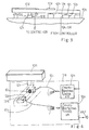
- Figure 8 illustrates the memory area assigned to a key status table, and the key status table has data storage areas assigned to the eighty-eight keys 10c/10d, respectively.
- the data storage areas of the first row KEY-POS are numbered from “0" to "95”
- the keyboard 10a contains the eighty-eight keys 10c/10d
- key number "0" to key number "87” are assigned to the black and white keys 10c/10d, respectively.
- the second row "KEY-RST" is assigned to pieces of positional information representative of the rest positions of the black and white keys 10c/10d, and the microprocessor 12aa writes the binary values of the digital key position signals DKP into the second row "KEY-RST".
- the third row to the seventh row THR-K1 to THR-K2A are respectively assigned to pieces of positional information representative of the thresholds K1, K2, K3, K4 and K2A calculated as described hereinbefore.
- the microprocessor 12aa calculates the thresholds K1, K2, K3, K4 and K2A for each key, the microprocessor 12aa transfers the thresholds K1 to K2A to the random access memory 12ad, and writes the thresholds K1 to K2A into the memory area corresponding to the third to seventh rows.
- the eighth row "KEY-STATE” is assigned to pieces of status information for the eighty-eight keys 10c/10d
- the ninth row "TBL-NUM” is assigned to pieces of control data information representative of table numbers of tone generation control tables.
- the tone generator 12ai has sixteen channels, and the sixteen channels are respectively accompanied with the tone generation control tables "0" to "15".
- the audio signal is tailored on the basis of the pieces of control data information stored in the tone generation control table specified by the table number in the ninth row "TBL-NUM".
- the tone generation control tables are stored in another memory area of the random access memory 12ad, and figure 9 illustrates the data storage areas of the tone generation control tables. Data are written into the data storage areas of the tone generation control tables through a data processing described hereinlater.
- the sixteen tone generation control tables are respectively assigned table numbers from "0" to "15", and the first row "KEY-NUM" is assigned to pieces of control data information indicative of the key numbers respectively assigned to the channels.
- the second to fourth rows are assigned to pieces of positional data information representative of the actual positions of a depressed key when the microprocessor 12aa acknowledges each key passing the thresholds K1, K2 and K3.
- the fifth to seventh rows are assigned to pieces of time data information representative of times when the microprocessor 12aa acknowledges each depressed key passing the thresholds K1, K2 and K3.
- the microprocessor 12aa periodically scans the output port of the analog-to-digital converter 12aj, and successively fetches the digital key position signals DKP for the eighty-eight keys.
- the time when the key actually passes the threshold is not always matched with the time when the microprocessor 12aa fetches the digital key position signal indicative of the pass at the threshold, and the pieces of positional data information is paired with the piece of time data information, and both are written into the tone generation control table.
- Each of the piece of time data information is two bytes long or a word.
- the eighth row "VELOCITY” is assigned to pieces of velocity data information each representative of a hammer velocity calculated for each depressed key
- the ninth row "DWN-CNTR" is assigned to pieces of time data information each representative of a time interval until a tone generation.
- the reason whey d2 is subtracted from d1 is that the normalized displacement ND is decremented from the rest position toward the end position.
- the divisor "rest position" normalizes the displacement, and 2 8 matches the bit string representative of the normalized displacement with the bit string representative of the pieces of time data information stored in the tone generation control tables.
- the microprocessor 12aa calculates the key velocity KV, and the key velocity KV is given by equation 7.
- KV (normalized displacement)/ ⁇ t2 - t1) x 2 8 ⁇
- t1 is the time passing the threshold Ki
- t2 is the time passing the threshold Kj.
- the divisor ''2 8 changes the piece of velocity data information from a two-byte data to a single byte data.
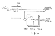
- the microprocessor 12aa accesses a converting table TB2 stored in the read only memory 12ac.
- the converting table TB2 defines the relation between the key velocities and hammer velocities, and corrects the error due to the non-linear characteristics of the photo-couplers.
- the converting table TB2 outputs a hammer velocity corresponding to the key velocity standardized in MIDI. The hammer velocity is supplied to the tone generation control tables, and written into the data storage areas of the eighth row "VELOCITY".
- Tables TB3-2, TB3-3 and TB3-4 store a relation between the hammer velocity and a time interval until a strike at the string 10f calculated on the assumption that the hammer assembly 10j continues the rotation at the hammer velocity.
- the three tables TB3-2 to TB3-4 are corresponding to the reference points k2, k3 and k4, and the hammer velocity is selectively supplied to the tables TB3-2, TB3-3 and TB3-4 depending upon the threshold Kj.
- the time interval is written into the data storage areas of the ninth row "DWN-CNTR" of the tone generation control tables.
- the hammer velocity is repeatedly calculated, and is compared with the previous hammer velocity. If the hammer velocity is larger than the previous hammer velocity, the piece of velocity data information and the piece of time data information indicative of the time interval are rewritten in the eighth row and the ninth row, respectively.
- the time interval is periodically decremented. When the time interval reaches zero, the key code representative of the key number and the hammer velocity are supplied from the tone generation control table to the tone generator 12ai, and the tone generator 12ai supplies the audio signal through the channel associated with the tone generation control table.
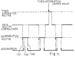
- the microprocessor 12aa selectively executes a main routine program, sub-routine programs branched from the main routine program, an A/D interruption routine and a timer interruption routine.
- Figure 11 illustrates the control sequence of the microprocessor 12aa.
- the microprocessor 12aa selectively executes the programs during periods indicated by thick bars. However, the thick bars do not exactly represent the time periods consumed by the microprocessor 12aa.
- the microprocessor 12aa starts the timer interruption at every 100 micro-second.
- the microprocessor 12aa increments the lapse of time stored in a timer assigned to one of built-in registers E6 incorporated in the microprocessor 12aa (see figure 12), and decrements the time intervals stored in the tone generation control tables, if any.
- the microprocessor may start at the initialization, and the lapse of time is assumed to be an absolute time or the present time.
- the microprocessor 12aa starts the A/D interruption at every 1 millisecond, and fetches the digital key position signals DKP. As described hereinbefore, the microprocessor 12aa fetches four digital key position signals at a time.
- the microprocessor 12aa gives the priority to the timer interruption, because the timer is expected to correctly indicate the lapse of time.
- the microprocessor 12aa processes the data for a tone generation through the main routine program and the associated sub-routine programs.
- the built-in register E6 is assigned the timer. Twenty-one registers E0-E6, R0H-R6H and R0L-R6L form in combination the built-in register array, and other six built-in registers are assigned jobs as follows.
- the register E5 is assigned to a time of the A/D conversion, and the key state is stored in the register R3H.
- the registers R3L to R6L respectively store a present key position, a table number assigned to the key to be targeted, a key number targeted by the microprocessor 12aa and a channel for the A/D conversion.
- the others E0-E4, R0H-R2H, R4H-R6H and R0L-R2L are general-purpose registers.
- Figure 13 illustrates the program sequence of the timer interruption routine.
- the timer interruption takes place at every 100 micro-second.
- the microprocessor 12aa is branched from the main routine program, and enters into the timer interruption routine program.
- the microprocessor 12aa firstly increments the lapse of time stored in the timer by one as by step ST100, and checks the lapse of time to see whether or not the lapse of time is euqal to a multiple of 8 as by step ST101. If the answer at step ST10 is given negative, the microprocessor 12aa returns to the main routine program.
- the microprocessor 12aa increments the lapse of time at every timer interruption, and the lapse of time is incremented by 100 micro-second at every timer interruption.
- step ST101 The answer at step ST101 is given affirmative at every 800 micro-second, and the microprocessor 12aa proceeds to step ST10.
- the microprocessor 12aa decrements the time intervals stored in the tone generation control tables, and checks the time intervals to see whether or not any one of the time intervals reaches zero. If there is a time interval decreased to zero, the microprocessor 12aa transfers the music data codes representative of the key code, the key-on and the hammer velocity to the tone generator 12ai, and writes key status "SOUND" to the eighth row "KEY-STATE" for the key.
- the key status "SOUND" represents that the tone generator is now producing the electronic sound for the key.
- the microprocessor 12aa clears the ninth row "TBL-NUM" for the key, and makes the tone generation control table storing the time interval decreased to zero open to a newly depressed key.
- the tone generator 12ai is allowed to tailor the audio signal on the basis of the music data codes.
- the microprocessor 12aa proceeds to step ST103, and checks the timer to see whether or not the lapse of time is equal to a multiple of 8192. If the answer is given negative, the microprocessor 12aa returns to the main routine program.
- step ST103 The answer at step ST103 is given affirmative at every 819.2 millisecond, and the microprocessor 12aa increments an over-time counter by one as by step ST104.
- the over-time counters are respectively provided for the sixteen channels, and are assigned to a memory area of the random access memory 12ad.
- the microprocessor 12aa aknowldeges the present key state is continued too long.
- the microprocessor 12aa returns to the main routine program.
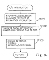
- Figure 14 illustrates the A/D interruption routine program.
- the analog-to-digital converter 12aj converts the analog key position signals AKP independently of the microprocessor 12aa.
- the analog-to-digital converter 12aj converts four analog key position signals AKP to the corresponding digital key position signals DKP
- the analog-to-digital converter 12aj requests an interruption to the microprocessor 12aa, and the microprocessor 12aa enters into the A/D interruption routine program.
- the microprocessor 12aa firstly interrupts the A/D conversion, and instructs the LED driver 12ak to supply the driving current to the next photo-emitting diode at every other interruption as by step ST201. Subsequently, the microprocessor 12aa fetches the four digital key position signals DKP, and writes the four digital key position signals DKP into the first row "KEY-POS" (see figure 8) for the four keys 10c/10d. The microprocessor 12aa further fetches the present time stored in the timer E6, and writes the present time into a table (see figure 15) assigned to one of the detecting channels "0" to "23" used for the digital key position signals DKP. The table shown in figure 15 is formed in the random access memory 12ad.
- the microprocessor proceeds to step ST203, and changes the detecting channel. If the present detecting channel is the last detecting channel "23", the microprocessor 12aa changes the present detecting channel to the first detecting channel "0". The microprocessor 12aa instructs the analog-to-digital converter 12aj to restart the analog-to-digital conversion.
- timings TM1, TM2 and TM3 are representative of the A/D interruption request, the interruption of the analog-to-digital conversion and the resumption of the analog-to-digital conversion.
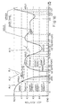
- the key state is described with reference to figure 16.
- the key is assumed to be depressed at time t1.
- the key successively passes the reference points k1, k2, k3 and k4 at times t2, t3, t4 and t5, respectively, and reaches the end position at time t6.
- Plots PL1 is representative of the trajectory of the depressed key, and the trajectory is typical.
- the depressed key has the key state "UPPER" between the rest position and the reference point k1, and changes the key state from "UPPER" to "TOUCH-A" between the reference points k1 and k2.
- the key state is successively changed from TOUCH-A to COUNT-DOWN “0" between the reference points k2 and k3, COUNT-DOWN “0” to COUNT-DOWN “1” between the reference points k3 and k4 and COUNT-DOWN “1” to COUNT-DOWN “2" after the reference point k4.
- the key state is changed to "SOUND".
- the key is staying at the end position between time t6 and time t7, and is released at time t7. After the release, the key is assumed to pass the reference points k4, k3 and k2 at time t8, t9 and t10. The key continuously maintained in the key state "SOUND" until time t10. When the key passes the reference point k2, the microprocessor acknowledges the key-off, and changes the key state to "HOLD".
- the key is depressed between the reference points K2 and k1, and is downwardly moved, again.
- the key passes the reference point k2 at time t11, and the key state is changed from HOLD to TOUCH-B.
- the key state is changed from TOUCH-B through COUNT-DOWN "1" and COUNT-DOWN "2" to SOUND.
- the key is released, and passes the reference points k4, k3 and k2 at times t15, t16 and t17.
- the microprocessor 12aa acknowledges the key-off at time t17, again, and the key enters into the key state HOLD.
- the key is depressed, again, before reaching the rest position, and the microprocessor 12aa gives the key state TOUCH-B to the key.
- the downward key motion is so slow that the key is maintained in "TOUCH-B" over a predetermined time period.
- the microprocessor 12aa gives the key state TIME-OVER to the key. The key does not enter into the key state SOUND, and returns to the rest position.
- the key may pass more than one reference point from the previously detected key position, and figure 17 illustrates such a quick key motion.
- the microprocessor checked the key position at time tp1, and checks the key position at time tp2, again. The player moves the key so fast that the key passes the reference points k1 and k2 between times tp1 and tp2.
- the microprocessor 12aa gives the key state COUNT-DOWN "3" to the key.
- the microprocessor 12aa gives the key state COUNT-DOWN "3" to the key.
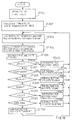
- FIG 18 illustrates the main routine program.
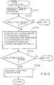
- the microprocessor 12aa starts the main routine program, initializes the built-in registers E0-E6, R0H-R6H and R0L-R6L and the random access memory 12ad, and starts the timer E6 as by step ST301. Thereafter, the microprocessor 12aa calculates the thresholds K1, K2, K3, K4 and K2A as described hereinbefore, and writes the thresholds K1, K2, K3, K4 and K2A into the key status table shown in figure 8 as by step ST302.
- the microprocessor 12aa proceeds to step ST303.
- the microprocessor 12aa load an initial key number to be processed into the register R5L or increments the key number in the register R5L by one. If the previous key number is "87", the microprocessor 12aa loads the key number "0" into the register R5L, again. Thus, the key 10c/10d to be targeted by the microprocessor 12aa is looped between "0" and "87".
- the microprocessor 12aa reads out the present key position and the time of the A/D conversion for the key to be targeted from the rows "KEY-POS" and "KEY-TIM".
- the present key position and the time of the A/D conversion are written into the register R3L and E5, respectively as by step ST304.
- the microprocessor 12aa has written the present key position and the time of the A/D conversion into the key status table and the table shown in figure 15 as described in connection with the A/D interruption routine.
- the microprocessor 12aa further reads out the key state of the key to be targeted, and write the key state into the register R3H as by step ST305.
- the microprocessor 12aa obtains the present key status for the key to be targeted, and sequentially makes decisions at steps ST306 to ST311.
- the microprocessor 12aa firstly checks the register R3L to see whether or not the key has passed the reference point k1. If the answer at step ST306 is given affirmative, the main routine program is branched to a sub-routine program ST400 for the key state "UPPER".
- step ST306 the microprocessor 12aa proceeds to step ST307, and checks the register R3H to see whether or not the key has entered into the key state COUNT-DOWN "1", COUNT-DOWN "2" or COUNT-DOWN "3". If the answer at step ST307 is given affirmative, the main routine program is branched to a sub-routine program ST450 for the key state "COUNT-DOWN".
- step ST307 when the answer at step ST307 is given negative, the microprocessor 12aa proceeds to step ST308, and checks the register R3H to see whether or not the key has entered into the key state TOUCH-A . If the answer at step ST308 is given affirmative, the main routine program is branched to a sub-routine program ST500 for the key state "TOUCH-A".
- step ST308 the microprocessor 12aa proceeds to step ST309, and checks the register R3H to see whether or not the key has entered into the key state SOUND. If the answer at step ST309 is given affirmative, the main routine program is branched to a sub-routine program ST450 for the key state "SOUND".
- step ST309 the microprocessor 12aa proceeds to step ST310, and checks the register R3H to see whether or not the key has entered into the key state HOLD. If the answer at step ST310 is given affirmative, the main routine program is branched to a sub-routine program ST600 for the key state "HOLD".
- step ST310 the microprocessor 12aa proceeds to step ST311, and checks the register R3H to see whether or not the key has entered into the key state OVER-TIME. If the answer at step ST311 is given affirmative, the main routine program is branched to a sub-routine program ST650 for the key state "OVER-TIME".
- step ST311 the microprocessor 12aa proceeds to the sub-routine program for the key state "TOUCH-B".
- the microprocessor 12aa After the execution of any one of the sub-routine programs 400, 450, 500, 550, 600, 650 and 700, the microprocessor 12aa returns to step ST303, and reiterates the loop consisting of the steps ST303-ST311 and any one of the sub-routine programs ST400-ST700.
- the microprocessor 12aa When the key has entered into the key state UPPER, the microprocessor 12aa enters into the sub-routine for UPPER.
- the microprocessor 12aa compares the present key position with the threshold K1, and checks the present key position stored in the register R3L to see whether or not the key has passes the reference point k1 as by step ST401. If the answer at step ST401 is given negative, the microprocessor 12aa admits that the key is still staying around the rest position, and returns to the main routine program.
- step ST401 the answer at step ST401 is given affirmative, and the microprocessor 12aa proceeds to step ST402 checks the tone generation control tables shown in figure 9 to see whether or not any one of the tone generation control tables is available for the key.
- the tone generator 12ai has sixteen channels, and, accordingly, the sixteen tone generation tables are prepared for controlling the tone generation. If one of the tone generation control tables is available for the key, the microprocessor 12aa assigns the table to the key, and writes the table number into the register R4L. However, if all the sixteen tone generation control tables have been already assigned to other keys, the microprocessor 12aa immediately returns to the main routine program.
- the microprocessor 12aa compares the present key position with the threshold K2 to see whether or not the key has passed the reference point k2 as by step ST403. If the answer at step ST403 is given negative, the key is downwardly moved at a standard key velocity, and the microprocessor 12aa proceeds to step ST404.
- the microprocessor 12aa rewrites the key state stored in the key status table from UPPER to TOUCH-A.
- the over-time counter associated with the tone generation control table is cleared, and the microprocessor 12aa writes the present key position and the time of A/D conversion stored in the registers R3L and E5 into the data storage areas OVR-K1 and OVK1-TIM of the tone generation control table.
- step ST403 when the answer at step ST403 is given affirmative, the key is downwardly moved at a high speed, and the microprocessor proceeds to step ST405.
- the microprocessor 12aa rewrites the key state stored in the key status table from UPPER to COUNT-DOWN "3", and writes "h7F" indicative of the predetermined maximum key velocity into the data storage area "VELOCITY" of the tone generation control table.
- the microprocessor 12aa determines a time interval on the basis of the maximum key velocity with reference to the table TB3-2, and writes a time interval into the data storage area "DWN-CNTR" of the tone generation control table.
- the microprocessor 12aa returns to the main routine program after either step ST404 or ST405.
- the microprocessor 12aa enters into the sub-routine for the key state "TOUCH-A".
- Figure 20 illustrates the sub-routine program for the key state TOUCH-A.
- the microprocessor 12aa checks the over-time counter to see whether or not the predetermined time period is expired as by step ST501.
- the over-time counter is incremented by one at every 100 micro-second (see figure 13), and, for this reason, the predetermined time period will be expired in so far as the counter is reset.
- step ST501 If the answer at step ST501 is given affirmative, the key traces the path indicated by broken lines BL1 (see figure 16), and the player is assumed to keep his finger on the key without further depressing.
- the microprocessor 12aa releases the tone generation control table from the assignment to the key, and changes the key state from TOUCH-A to HOLD as by step ST502. Even though the player keeps the key in the key state HOLD, the player may further depress the key (see the key motion from time t11 to time t14), and the controller 12c can cope with the key motion as will be described hereinlater. Thereafter, the microprocessor 12aa returns to the main routine program.
- the microprocessor 12aa checks the register R3L to see whether or not the key has passed the reference point k3 as by step ST503. If the answer at step ST503 is given affirmative, the player is assumed to accelerate the key, and the key successively passes the reference points k2 and k3 within the time period from the previous scanning as similar to the key motion between time tp3 and time tp4 (see figure 17).
- the microprocessor 12aa changes the key state stored in the data storage area KEY-STATE of the key status table from TOUCH-A to COUNT DOWN "3", and writes the maximum hammer velocity "h7F” and the time interval corresponding to the maximum hammer velocity into the data storage areas VELOCITY and DWN-CNTR of the tone generation control table as by step ST504. Thereafter, the microprocessor 12aa returns to the main routine program.
- step ST503 When the answer at step ST503 is given negative, the microprocessor repeats the check to see whether or not the key has passed the reference point k2 as by step ST505. If the answer at step ST505 is given affirmative, the key is tracing the plots PL1 from time t2 through time t3 (see figure 16), and the microprocessor 12aa proceeds to step ST506.
- the microprocessor 12aa changes the key state in the data storage area of the key status table from TOUCH-A to COUNT-DOWN "0", and transfers the present key position stored in the register R3L and the time of A/D conversion stored in the register E5 to the tone generation control table.
- the present key position and the time of A/D conversion are written into the data storage areas OVR-K2 and OVK2-TIM.
- the key position and the time of A/D conversion have been already written into the data storage areas OVR-K1 and OVK1-TIM (see step ST404 in the sub-routine for the key state UPPER).
- the microprocessor 12aa calculates the key velocity, and writes the hammer velocity and a time interval corresponding to the hammer velocity into the data storage areas VELOCITY and DWN-CNTR of the tone generation control table.
- step ST505 When the answer at step ST505 is given negative, the microprocessor checks the register R3L again to see whether or not the key is still under the reference point k1 as by step ST507. If the answer at step ST507 is given affirmative, the key is still traveling through the space between the reference points k2 and k3, and the microprocessor 12aa returns to the main routine program.
- step ST507 when the answer at step ST507 is given negative, the player is assumed to remove his finger from the key, and the key is upwardly moved as indicated by broken lines BL2 (see figure 16).
- the microprocessor releases the tone generation control table from the assignment to the key, and changes the key position from TOUCH-A to UPPER as by step ST508. Thereafter, the microprocessor 12aa returns to the main routine program.
- the microprocessor 12aa If the key state has entered into COUNT-DOWN "1", COUNT-DOWN "2" or COUNT-DOWN "3", the microprocessor 12aa is branched from the main routine program to the sub-routine program for the key state COUNT-DOWN shown in figure 21.
- the microprocessor 12aa firstly checks the register R3L whether or not the key has passed the reference point K2 as by step ST451. If the answer at step ST451 is given negative, the key returns toward the rest position, and the microprocessor 12aa makes the tone generation control table assigned to the key at step ST402 open to a depressed key as by step ST452.
- the microprocessor compares the present key position with the threshold K1 to see whether or not the key is under the reference point k1 as by step ST453. If the answer at step ST453 is given negative, the key has returned to a position close to the rest position, and the microprocessor 12aa rewrites the key state from COUNT-DOWN "1", “2” or “3” to UPPER as by step ST454. Thereafter, the microprocessor 12aa returns to the main routine program. On the other hand, if the answer at step ST453 is given affirmative, the microprocessor 12aa rewrites the key state from COUNT-DOWN "1", "2" or "3” to HOLD as by step ST455. Thereafter, the microprocessor 12aa returns to the main routine program.
- the microprocessor 12aa checks the register R3H to see whether or not the key state is COUNT-DOWN "2" or COUNT-DOWN "3" as by step ST456. If the answer is given affirmative, the microprocessor 12aa returns to the main routine program. On the other hand, when the answer at step ST456 is given negative, the microprocessor 12aa checks the register R3L to see whether or not the key has passed the reference point K3 as by step ST457. If the answer at step ST457 is given negative, the key is still between the reference points k2 and k3, and the microprocessor 12aa returns to the main routine program.
- step ST457 when the answer at step ST457 is given affirmative, the microprocessor 12aa compares the present key position with the threshold K4 to see whether or not the key has downwardly passed the reference point k4 as by step ST458. If the answer at step ST458 is given negative, the microprocessor checks the register R3H to see whether or not the key state is COUNT-DOWN "0" as by step ST459. If the answer at step ST459 is given affirmative, the key passes the next reference point, and enters into the key state COUNT-DOWN "1".
- the microprocessor 12aa rewrites the key state from COUNT-DOWN “0" to COUNT-DOWN "1", and determines the hammer velocity between the reference points k1 and k3 and the time interval corresponding thereto as by step ST460. If the new hammer velocity is larger than the hammer velocity stored in the tone generation control table, the key is accelerated, and the microprocessor 12aa writes the new hammer velocity and a corresponding time interval into the data storage areas VELOCITY and DWN-CNTR of the tone generation table. Thereafter, the microprocessor 12aa returns to the main routine program.
- the tone generation control table stores the key position and the time for the reference point k1, and the registers R3L and E5 stores the present key position and the present time for the reference point k3.
- the answer at step ST459 is given negative, the key is still within the key state COUNT-DOWN "1", and the microprocessor 12aa returns to the main routine program.
- the microprocessor 12aa When the answer at step ST458 is given affirmative, the microprocessor 12aa also checks the register R3H to see whether or not the key state is COUNT-DOWN "0" as by step ST461. If the answer at step ST461 is given affirmative, the key has passes the reference points k3 and k4, and the microprocessor 12aa proceeds to step ST462. The microprocessor 12aa rewrites the key state to COUNT-DOWN "3" in the data storage area KEY-STATE of the key status table, and changes the hammer velocity and the time interval in the tone generation control table to the maximum values. Thereafter, the microprocessor 12aa returns to the main routine program.
- step ST461 When the answer at step ST461 is given negative, the microprocessor proceeds to step ST463.
- the microprocessor 12aa changes the key state to COUNT-DOWN "2", and determines the hammer velocity and the time interval corresponding thereto on the basis of the key positions and the times at the reference points k2 and k4. If the new hammer velocity and the new time interval are larger than the hammer velocity and the interval stored in the tone generation table, the key is accelerated, and the microprocessor 12aa rewrite the data storage areas VELOCITY and DWN-CNTR to the new hammer velocity and the new time interval.
- the key position and the time at the reference point k2 are read out from the tone generation control table, and the registers R3L and E5 store the key position and the time at the reference point k4.
- the microprocessor 12aa returns to the main routine program.
- step ST451 to ST452 if a player depresses the key for a staccato, there is a possibility to proceed from step ST451 to ST452.
- the microprocessor 12aa releases the tone generation control table at step ST452 without a generation of sound.
- most of staccato does not cause the microprocessor 12aa to proceed from step ST451 to step ST452, and the staccato is exactly reproduced.
- the microprocessor 12aa does not release the tone generation control table in so far as the time interval has been written into the data storage area DWN-CNTR, the control sequence can perfectly reproduce any kind of fingering on the keyboard 10a.
- the microprocessor 12aa periodically decrements the value in the data storage area during the timer interruption as described hereinbefore.
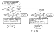
- the key status is changed to SOUND (see step ST102), and the microprocessor 12aa is branched from the main routine program to the sub-routine program for the key state SOUND.
- the microprocessor 12aa Upon entry into the sub-routine program SOUND, the microprocessor 12aa checks the register R3L to see whether or not the key has upwardly passed the reference point k2 as by step ST551. If the answer at step ST551 is given affirmative, the microprocessor 12aa enters into a sub-routine program for a released key as by step ST552, and the sub-routine program for a released key is described hereinlater.
- the microprocessor 12aa supplies the music data code representative of "key-off", which is corresponding to "MIDI OFF" of the MIDI standards, to the tone generator 12ai as by step ST553, and the tone generator 12ai rapidly terminates the electronic sound.
- the microprocessor 12aa checks the register R3L to see whether or not the key is below the reference point k1 as by step ST554. If the answer at step ST554 is given negative, the key is getting closer and closer to the rest position, and the microprocessor 12aa changes the key state stored in the data storage area of the key status table from SOUND to UPPER as by step ST555. Thereafter, the microprocessor 12aa returns to the main routine program.
- step ST554 when the answer at step ST554 is given affirmative, the player still lightly depresses the key, and the microprocessor 12aa changes the key state from SOUND to HOLD as by step ST556. Thereafter, the microprocessor 12aa returns to the main routine program.
- the key state SOUND is broken down into SOUND-0 sub-state and SOUND-1 sub-state.
- the sub-state SOUND-1 is larger in damping factor than the sub-state SOUND-0.
- the sub-state SOUND-0 and the sub-state SOUND-1 are corresponding to the MIDI codes (AX XX 00) and (AX XX 01), respectively.
- the key entered into the sub-state SOUND-0 through step ST102, and the key is staying in the sub-state SOUND-0 during the tone generation.
- the microprocessor 12aa Upon entry into the sub-routine program for a released key, the microprocessor 12aa checks the register R3H to see whether or not the key state is the sub-state SOUND-0 as by step ST557. The key has entered into the sub-state SOUND-0 during the tone generation, and the answer at step ST557 is given affirmative. The microprocessor 12aa checks the register R3L to see whether or not the key has is still under the reference point k2A as by step ST558. If the answer at step ST558 is given affirmative, the key remains deep, and the microprocessor 12aa returns to the main routine program.
- step ST558 if the answer at step ST558 is given negative, the microprocessor 12aa rewrites the release rate to a large value such as (AX XX 01), and changes the key state from SOUND-0 to SOUND-1 as by step ST559.
- the large release rate causes the tone generator 12ai to accelerate the termination of the electronic sound. Thereafter, the microprocessor 12aa returns to the main routine program.
- step ST557 When the answer at step ST557 is given negative, the key state was changed to SOUND-1 at step ST559 in the previous processing, and the microprocessor 12aa checks the register R3L to see whether or not the key is still under the reference point k2A as by step ST560. If he answer at step ST560 is given negative, the key is in the shallow range, and the microprocessor 12aa returns to the main routine program.
- the player makes the key deep again.
- the microprocessor 12aa changes the key state to SOUND-0, and decreases the release rate to, for example, (AX XX 00) represented by the MIDI code.
- the tone generator 12ai gradually terminates the sound as similar to a piano sound naturally extinguished.
- the controller 12c changes the release rate depending upon the key position.
- an acoustic piano takes up the vibrations of a string with a damper head.
- the damper head differently extinguishes the sound depending upon the fingering. If the damper head repeats the touch and release, the sound is prolonged.
- the controller 12c faithfully reproduces these sound termination.
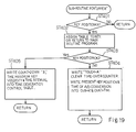
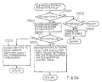
- Figure 24 illustrates the sub-routine for the key state HOLD.
- the microprocessor 12aa checks the register R3L to see whether or not the key is under the reference point k2A as by step ST601. If the answer at step ST601 is given negative, the microprocessor 12aa further checks to see whether or not the key is under the reference point k1 as by step ST602. In case where the key remains depressed between the reference points k2 and k1, the answer at step ST602 is given affirmative, and the microprocessor 12aa returns to the main routine program.
- step ST602 when the answer at step ST602 is given negative, the key is getting closer and closer to the rest position, and the microprocessor 12aa changes the key state from HOLD to UPPER as by step ST603. Thereafter, the microprocessor 12aa returns to the main routine program.
- step ST601 When the answer at step ST601 is given affirmative, the player depresses the key again, and the microprocessor 12aa proceeds to step 604.
- the microprocessor 12aa tries to assign one of the sixteen channels to the key. If there is an open channel, the microprocessor 12aa assigns the open channel to the key. However, all the channels have already assigned to other keys, and the microprocessor 12aa returns to the main routine program without a key assignment.
- the microprocessor 12aa When an open channel is assigned to the key, the microprocessor 12aa checks the register R3L to see whether or not the key has passed the reference point k3 as by step ST605. If the answer at step ST605 is given affirmative, the key has passed two reference points k2 and k3 at a high speed as similar to the key motion between time tp3 and tp4. The microprocessor 12aa changes the key state from HOLD to COUNT-DOWN "3", and writes the maximum hammer velocity "h7F" and the corresponding time interval into the data storage areas VELOCITY and DWN-CNTR of the tone generation control table assigned thereto as by step ST606. Thereafter, the microprocessor 12aa returns to the main routine program.
- step ST605 When the answer at step ST605 is given negative, the key is downwardly moved within the standard velocity range as similar to the key motion between time t11 and time t12, and the microprocessor 12aa proceeds to step ST607.
- the microprocessor 12aa changes the key state from HOLD to TOUCH-B, and resets the over-time counter.
- the microprocessor 12aa transfers the present key position and the time of A/D conversion from the registers E5 and R3L to the tone generation control table assigned thereto, and writes them into the data storage areas OVR-K2 and OVK2-TIM.
- the microprocessor 12aa stores the key position when the key passes the threshold K2 and the time when the key passes the threshold K2, and returns to the main routine program.
- Figure 25 illustrates the sub-routine program for the key state TOUCH-B.
- the microprocessor 12aa firstly checks the over-time counter to see whether or not the over-time counter exceeds the predetermined time period as by step ST701. If the answer at step ST702 is given affirmative, the key staggers between the reference points k2 and k3 (see figure 16), by way of example, and there is little possibility to strike a string through a similar key motion of an acoustic piano.
- the microprocessor 12aa releases the tone generation table from the assignment to the key, and changes the key state from TOUCH-B to OVER-TIME as by step ST702 . Thereafter, the microprocessor 12aa returns to the main routine program.
- step ST701 when the answer at step ST701 is given negative, the microprocessor 12aa checks the register R3L to see whether or not the key is under the reference point k4 as by step ST703. If the answer at step ST703 is given affirmative, the player strongly depressed the key, and the key has passed two reference points k3 and k4, and the microprocessor 12aa proceeds to step ST704.
- the microprocessor 12aa writes the maximum hammer velocity and the corresponding time interval into the data storage areas VELOCITY and DWN-CNTR of the tone generation control table assigned thereto. Thereafter, the microprocessor 12aa returns to the main routine program.
- the microprocessor 12aa checks the register R3L again to see whether or not the key is under the reference point k3 as by step ST705. If the answer at step ST705 is given affirmative, the key is moved within the standard velocity range, and the microprocessor 12aa proceeds to step ST706.
- the microprocessor 12aa fetches the time and the key position for the reference point k2 from the data storage areas OVR-K2 and OVK2-TIM and the present key position and the time of A/D conversion from the registers R3L and E5, and calculates the key velocity.
- the microprocessor 12aa converts the key velocity to the hammer velocity with reference to the converting table TB2, and determines a time interval corresponding to the hammer velocity with reference to the table TB3-2.
- the microprocessor 12aa transfers the hammer velocity and the time interval to the tone generation table assigned thereto, and writes the hammer velocity and the time interval into the data storage area VELOCITY and DWN-CNTR. Thereafter, the microprocessor 12aa returns to the main routine program.
- step ST705 When the answer at step ST705 is given negative, the microprocessor 12aa checks the register R31 again to see whether or not the key is under the reference point k2 as by step ST707. If the answer is given affirmative, the key is still within the range between the reference points k2 and k3, and the microprocessor 12aa returns to the main routine program.
- step ST707 When the answer at step ST707 is given negative, there is little possibility to strike a string through a similar key motion of an acoustic piano, and the microprocessor 12aa releases the tone generation table from the assignment to the key as by step ST708. Thereafter, the microprocessor 12aa proceeds to step ST709 to see whether or not the key is under the reference point k1. If the answer at step ST709 is given negative, the key returns toward the rest position, and the microprocessor 12aa changes the key position to UPPER as by step ST710. On the other hand, when the answer at step ST709 is given affirmative, the microprocessor 12aa changes the key position to HOLD as by step ST711. After steps ST710 or ST711, the microprocessor 12aa returns to the main routine program.
- Figure 26 illustrates the sub-routine program for the key state OVER-TIME.
- the microprocessor 12aa checks the register R3L to see whether or not the key is still under the reference point k2 as by step ST651. If the answer at step ST651 is given affirmative, the microprocessor 12aa returns to the main routine program. Thus, even if the key is depressed again after the entry into the key state OVER-TIME, no sound is generated. If a key of an acoustic piano is depressed to the end position after the stagger between the reference points k2 and k3 over a predetermined time period, the key action mechanism associated therewith does not cause the associated hammer assembly to strike the string.
- the control sequence through step ST651 is corresponding to the key motion of the acoustic piano, and the keyboard musical instrument according to the present invention exactly simulates the tone generation through different key motions of the acoustic piano.
- step ST651 when the answer at step ST651 is given negative, the microprocessor 12aa proceeds to step ST652 to see whether or not the key is under the reference point k1. If the answer at step 652 is given affirmative, the key is moved as similar to the key motion between times t21 and t22, and the microprocessor 12aa changes the key state to HOLD as by step ST653. The microprocessor 12aa returns to the main routine program.
- step ST652 When the answer at step ST652 is given negative, the key is getting closer and closer to the rest position as similar to the key position between times t22 and t23, and the microprocessor 12aa changes the key state to UPPER as by step ST654. Thereafter, the microprocessor 12aa returns to the main routine program.
- the microprocessor 12aa checks the present key position, and selectively enters into the sub-routine programs.
- the interrelation between the sub-routine programs is illustrated in figure 27.
- the microprocessor 12aa executes steps ST402, ST403 and ST404, and assigns one of the tone generation control table.
- the key state is changed to TOUCH-A, and the controller 12c is ready for a tone generation.
- the microprocessor 12aa is branched from the main routine program to the sub-routine program for the key state TOUCH-A.
- the key passes the reference point k2 at time t2, and the microprocessor 12aa is branched from the main routine program to the sub-routine for the key state TOUCH-A.
- the microprocessor 12aa determines the hammer velocity and the time interval corresponding thereto through the execution of steps ST501, ST503, ST505 and ST506, and changes the key state from TOUCH-A to COUNT-DOWN "0". For this reason, the microprocessor 12aa is, thereafter, branched from the main routine program to the sub-routine program for the key state COUNT-DOWN.
- the key 10c/10d passes the reference point k3 at time t4, and the microprocessor 12aa executes the steps ST457, ST458, ST459 and ST460 so as to determine the hammer velocity and the corresponding time interval.
- the key state is changed from COUNT-DOWN "0" to COUNT-DOWN "1", and the microprocessor 12aa counts down the time interval at every timer interruption.
- the key 10c/10d passes the reference point k4 at time t5, and the microprocessor 12aa executes steps ST458, ST461 and ST463.
- the microprocessor 12aa determines the hammer velocity and the corresponding time interval, and changes the hammer velocity and the time interval from the previous values to the new values if the key 10c/10d is accelerated.
- the microprocessor 12aa repeats the calculation of the key velocity, and repeatedly determines the hammer velocity and the time interval. If the new hammer velocity is larger than the previous hammer velocity, the microprocessor 12aa changes the hammer velocity and the time interval to new values.
- the microprocessor 12aa changes the key state to COUNT-DOWN "2", and repeats the calculation of the key velocity and the determination of the hammer velocity and the time interval. Thus, the largest hammer velocity and the corresponding time interval are left in the data storage areas VELOCITY and DWN-CNTR. When the time interval reaches zero, the microprocessor 12aa transfers the music data codes to the tone generator 12ai for generating a sound, and changes the key state to SOUND.
- the player releases the key at time t7, and the key is upwardly moved toward the rest position.
- the key passes the reference point k2 at time t10, and the microprocessor 12aa transfers the music data code representative of key-off to the tone generator 12ai through the execution of steps ST551 and ST553. Thereafter, the microprocessor 12aa changes the key state to HOLD at step ST556.
- the player depresses the key 10c/10d again, and the key 10c/10d passes the reference point k2 at time t11.
- the microprocessor 12aa assigns one of the tone generation control tables to the key 10c/10d again through the execution of step ST604, and changes the key state to TOUCH-B at step ST607.
- the key passes the reference point k3 at time t12 and the reference point k4 at time t13, and the microprocessor 12aa repeats the execution of the sub-routine program for the key state COUNT-DOWN.
- the time interval reaches zero at time t14, and the microprocessor 12aa transfers the music data codes for the tone generation to the tone generator 12ai, again.
- the key 10c/10d enters the key state HOLD at time t17,
- the player depresses the key 10c/10d again, and the key 10c/10d enters into the key state TOUCH-B at time t18, again. However, the player maintains the key 10c/10d between the reference points k2 and k3 over the predetermined time period, and the predetermined time period stored in the over-time counter expires. Then, the key state is changed to OVER-TIME. The hammer velocity and the time interval are not determined, and no sound is generated thereafter.
- the key 10c/10d passes the reference point k2 at time t21 and the reference point k1 at time t22, and the key state is changed through HOLD to UPPER.
- the key 10c/10d If the player maintains the key 10c/10d between the reference points k1 and k2 over the predetermined time period as indicated by the broken lines BL1, the key 10c/10d enters into the key state OVER-TIME. On the other hand, if the key 10c/10d upwardly returns as indicated by the broken lines BL2, the key 10c/10d enters into the key state UPPER.
- the key 10c/10d upwardly returns as indicated by broken lines BL3
- the key 10c/10d enters into the key state HOLD through the execution of steps ST709 and ST711.
- the key 10c/10d proceeds from the key position P1 to the key position P2 between two sampling works on the key 10c/10d (see figure 17), and the microprocessor 12aa determines the maximum hammer velocity and the corresponding time interval during the execution of the sub-routine program for the key state UPPER.
- the key 10c/10d enters into the key state COUNT-DOWN "3", and the microprocessor 12aa transfers the music data codes for the tone generation to the tone generator when the time interval reaches zero.
- the key motion between the key positions P3 and P4 is similarly processed.
- the microprocessor 12aa enters into the sub-routine program for the release, and changes the release rate. As a result, the sound is delicately extinguished.
- a player plays music through the acoustic sounds in an acoustic sound mode. While the keyboard musical instrument is staying in the acoustic sound mode, the silent system 11 maintains the cushion units 11b at the free position FP, and the hammer heads 10j can strike the associated strings 10f without an interruption of the cushion units 11b.
- the white key 10d turns in the counter clockwise direction in figure 2, and the capstan button 10k pushes the heel 10hc upwardly.
- the whippen assembly 10hb and the jack 10he turn around the whippen flange 10ha in the clockwise direction, and the jack 10he urges the hammer assembly 10j to turn around the butt flange 10jb in the clockwise direction.
- the whippen assembly 10hb which is still turning around the whippen flange 10ha, causes the jack 10he to turn around the jack flange 10hd in the counter clockwise direction against the jack spring 10hf. Then, the jack quickly turns around the jack flange 10hd in the counter clockwise direction, and the hammer butt 10ja escapes from the jack 10ja.
- the hammer assembly 10j starts the free rotation toward the string 10f, and strikes it.
- the string 10f vibrates, and generates the acoustic sound.
- the hammer assembly rebounds on the string 10f, and turns in the counter clockwise direction.
- the catcher 10je is brought into collision with the back check 10jf, and temporally rests on the back check 10jf.
- the whippen assembly 10hb turns around the whippen flange 10ha in the counter clockwise direction, and the jack 10he returns to the initial position beneath the butt skin 10ji.
- the player selectively depresses the black and white keys 10c and 10d, and the hammer heads 10jd associated with the depressed keys 10c/10d strike the strings 10f so as to generate the acoustic sounds for the music.
- the player changes the cushion units 11b to the blocking position BP. While the player is fingering on the keyboard 10a, the white key 10d is assumed to be depressed. The white key 10d turns in the counter clockwise direction, and the capstan button 10k pushes the heel 10hc upwardly. The whippen assembly 10hb and the jack 10he turn around the whippen flange 10ha in the clockwise direction, and the jack 10he urges the hammer assembly 10j to turn around the butt flange 10jb in the clockwise direction.
- the whippen assembly 10hb causes the jack 10he to turn around the jack flange 10hd in the counter clockwise direction against the jack spring 10hf. Then, the jack quickly turns around the jack flange 10hd in the counter clockwise direction, and the hammer butt 10ja escapes from the jack 10ja. The player feels the key touch as usual.
- the hammer assembly 10j starts the free rotation toward the string 10f. However, the catcher 10je rebounds on the cushion unit 11b before the hammer head 10jd reaches the string 10f. The hammer assembly 10j returns to the home position without a strike at the string 10f, and no acoustic sound is generated in the silent mode.
- the controller 12c While the player is practicing the fingering on the keyboard 11a, the controller 12c produces the music data codes through the execution of the A/D interruption routine program, the main routine program, the sub-routine programs and the timer interruption routine program, and produces the audio signal from the music data codes.
- the audio signal is supplied to the headphone 12d and/or the speaker system 12e, and the headphone 12d and/or the speaker system 12e generates the electronic sounds corresponding to the depressed keys 10c/10d.
- the electronic system 12 While a player is performing music, the electronic system 12 generates the music data codes through the execution of the A/D interruption routine program, the main routine program, the sub-routine programs and the timer interruption routine program, and the music data codes are transferred to the floppy disk driver 12am.
- the music data codes are written into the floppy disk 12an. If the cushion units 11b is in the free position FP, the hammer heads 10jd strike the associated strings 10f, and the keyboard musical instrument generates the acoustic sounds in response to the fingering. On the other hand, when the cushion units 11b is in the blocking position BP, the electronic sounds are produced through the headphone 12d/speaker system 12e.
- the music data codes are transferred from the floppy disk 12an to the random access memory 12ad, and the microprocessor 12aa instructs the driver circuit 12ao to selectively supply the driving current signals to the solenoid-operated actuators 12b.
- the solenoid-operated actuators 12b move the associated keys 10c/10d as if the player repeats the fingering on the keyboard 10a, and the hammer heads 12jd strike the strings 10f.
- the intensity of each impact is regulated to the original intensity, and the original performance is exactly reproduced.
- the LED driver 12ak, the A/D converter 12aj, the A/D interruption routine program and steps ST401, ST403, ST451, ST453, ST457, ST458, ST503, ST505, ST507, ST551, ST554, ST558, ST560, ST601, ST602, ST605, ST651, ST652, ST703, ST705, ST707 and ST709 realize a discriminating sub-means.
- a key-state determining sub-means is realized by steps ST306-311, ST404, ST405, ST404, ST455, ST454, ST455, ST460, ST462, ST463, ST504, ST506, ST555, ST556, ST559, ST561, ST603, ST606, ST607, ST653, ST654, ST704, ST706, ST711 and ST710.
- Step ST101, ST553, ST559 and ST561 realize a control information generating sub-means.
- the shaft member 11a may be connected through links and a wire to a nob or a pedal, and a player changes the cushion units 11b between the free position FP and the blocking position BP by manipulating the nob or the pedal.
- the cushion members 11b may enter into trajectories of other parts of the hammer assemblies 10j so as to cause the other parts to rebound thereon.
- the other parts may be the hammer shanks 10jc or extensions attached to the leading ends of the hammer shanks 10jc.
- the keyboard musical instrument may generate electronic sounds having a timbre different from a piano sound.
- the tone generator tailors the envelop representative of the different timbre.
- the sub-routine program may control another part of the envelop such as a sustain.
- the present invention is available for an electronic keyboard musical instrument without a key action mechanism, a damper mechanism, a hammer assembly and a string.
- the key position signals AKP may be available for a feedback control in the playback mode.
- the key velocity is calculated from the key motion between the reference points k1 and k2 in TOUCH-A, between k1 and k3 in COUNT-DOWN "0" and between k2 and k4 in COUNT-DOWN "1".
- the key velocity may be calculated on the basis of a key motion between different reference points such as k2 and k3 in COUNT-DOWN "0".
- the section between the reference points k2 and k3 may be divided into sub-sections as shown in figure 28.
- the damping factor during the extinguishment of a natural sound is gradually increased as represented by an arrow AR1, and the release rate is changed from (AX XX 00) through (AX XX 01) at point k2C, (AX XX 02) at point k2B and (AX XX 03) at point k2A.
- Figure 29 illustrates the envelop stepwise decreased as shown in figure 28. An extinguishment of natural sound is exactly simulated by the envelop.
- the reference points may be changed depending upon the player and/or a music score to be performed.
- the key velocity is repeatedly calculated, and the new hammer velocity is compared with the previous hammer velocity so as to determine whether or not the previous hammer velocity and the previous time interval are replaced with the new hammer velocity and the new time interval.
- the new time interval may be compared with the previous time interval, and the comparison of the new time interval with the previous time interval is expected to enhance the precision. Nevertheless, the present inventor confirmed that the comparison in the hammer velocity was matched with the comparison in the time interval, and the comparison in the hammer velocity was smaller in the amount of calculation than the comparison in the time interval.
Landscapes
- Physics & Mathematics (AREA)
- Engineering & Computer Science (AREA)
- Acoustics & Sound (AREA)
- Multimedia (AREA)
- Electrophonic Musical Instruments (AREA)
Claims (10)
- Tastenmusikinstrument zum Erzeugen von Klängen, wobei das Tastenmusikinstrument folgendes aufweist:dadurch gekennzeichnet,eine Tastatur bzw. Klaviatur (10a) mit einer Vielzahl von Tasten (10c/10d), die jeweils zwischen einer Ruheposition und einer Endposition hin- und herbewegt werden;Ton- bzw. Klangerzeugungsmittel (12ai/12d/12e; 12ao/12b/10h/10j/10f), die auf eine erste Steuerinformation ansprechen, um mit der Erzeugung eines Klangs zu beginnen, welcher durch jede der Vielzahl von Tasten vorgegeben ist, wenn sie zu der Endposition hin bewegt wird, sowie auf eine zweite Steuerinformation ansprechen, um den Klang zu beenden, wenn die Taste zur Ruheposition hin bewegt wird;eine Vielzahl von Tastensensoren (12a), die jeweils die Vielzahl von Tasten (10c/10d) überwachen zum Erzeugen von Tastenpositionssignalen (AKP), die jeweils repräsentativ sind für Bewegungen der zugehörigen Tasten; undTon- bzw. Klangsteuermittel (12c), die mit der Vielzahl von Tastensensoren (12a) verbunden sind und die Ton- bzw. Klangerzeugungsmittel steuern,
daß jedes der Tastenpositionssignale einen Wert besitzt, welcher sich kontinuierlich ändert entlang einer Bahn einer der Vielzahl von Tasten (10c/10d), wobei jede Taste eine Vielzahl von Bezugspunkten (k1-k4/k2A) besitzt, die Abschnitte der Bahn begrenzen, und
daß die Ton- bzw. Klangsteuermittel (12c) folgendes umfassen:Unterscheidungsmittel (12ak, 12aj, ST201-ST203, ST401, ST403, ST551, ST453, ST457, ST458, ST503, ST505, ST507, ST551, ST554, ST558, ST560, ST601, ST602, ST605, ST651, ST652, ST703, ST705, ST707 und ST709), die periodisch den Wert jedes der Vielzahl von Tastenpositionssignalen mit entsprechenden Schwellenwerten der Vielzahl von Bezugspunkten (k1-k4/k2A) vergleichen, um einen entsprechenden Abschnitt zu bestimmen, in dem jede der Vielzahl von Tasten (10c/10d) bewegt wird,Tastenzustandsbestimmungsmittel (ST306-311, ST404, ST405, ST404, ST455, ST454, ST455, ST460, ST462, ST463, ST504, ST506, ST555, ST556, ST559, ST561, ST603, ST606, ST607, ST653, ST654, ST704, ST706, ST711 und ST710) zum Bestimmen eines aktuellen Tastenzustands von jeder der Vielzahl von Tasten (10c/10d) auf der Grundlage des entsprechenden Abschnitts und eines vorhergehenden Tastenzustands, welcher vorher durch die Unterscheidungsmittel bestimmt wurde, undSteuerinformationserzeugungsmittel (ST101, ST553, ST559 und ST561) zum Erzeugen einer ersten Steuerinformation als Anzeige für eine Klang- bzw. Tonerzeugung für jede der Vielzahl von Tasten (10c/10d), nachdem der aktuelle Tastenzustand repräsentativ ist für einen Zustand, in dem eine Klang- bzw. Tonerzeugung beabsichtigt ist, wobei die Steuerinformationserzeugungsmittel ferner eine zweite Steuerinformation erzeugen als Anzeige für eine Beendigung des Klangs bzw. Tons für jede der Vielzahl von Tasten (10c/10d), wenn der Wert der Vielzahl von Tastenpositionssignale mit einem der Schwellenwerte übereinstimmt, und zwar nach dem Eintritt in einen Zustand, in dem die Tonerzeugung beabsichtigt ist. - Tastenmusikinstrument gemäß Anspruch 1, wobei die Ton- bzw. Klangerzeugungsmittel einen Ton- bzw. Klanggenerator (12ai) umfassen zum Erzeugen eines elektronischen Klangs ansprechend auf die ersten und zweiten Steuerinformationen.
- Tastenmusikinstrument gemäß Anspruch 2, wobei die Ton- bzw. Klangerzeugungsmittel ferner eine Vielzahl von Saiten (10f) zum Erzeugen akustischer Klänge, eine Vielzahl von Hammeranordnungen (10j) zum Anschlagen der Vielzahl von Saiten, und eine Vielzahl von Tastenmechaniken (10h) umfassen, die ansprechend sind auf ein (Finger-)Spiel auf der Klaviatur, um die Hammeranordnungen selektiv zur Drehung anzutreiben.
- Tastenmusikinstrument gemäß Anspruch 3, wobei die Ton- bzw. Klangerzeugungsmittel ferner eine Vielzahl von elektromagnetbetätigten Betätigern (12b) umfassen, die jeweils mit der Vielzahl von Tasten (10c/10d) assoziiert sind und wahlweise durch Treibersignale erregt werden, um die zugehörigen Tasten aus der Vielzahl von Tasten zu bewegen, sowie eine Treiberschaltung (12ao), die ansprechend ist auf die ersten und zweiten Steuerinformationen, um selektiv die Treibersignale an die Vielzahl von elektromagnetbetätigten Betätigern zu liefern.
- Tastenmusikinstrument gemäß Anspruch 3 oder 4, wobei das Tastenmusikinstrument ferner einen Stummschaltungsmechanismus (11) aufweist, der zwischen einer freien Position (FP) und einer Blockierposition (BP) umgeschaltet wird, wobei die Blockierposition bewirkt, daß die Vielzahl von Hammeranordnungen (10j) von dem Stummschaltungsmechanismus abprallen, bevor sie die Vielzahl von Saiten (10f) anschlagen, und wobei die freie Position gestattet, daß die Vielzahl von Hammeranordnungen (10j) die Vielzahl von Saiten (10f) anschlägt.
- Tastenmusikinstrument gemäß einem der vorhergehenden Ansprüche, wobei die Vielzahl von Tastensensoren (12a) in eine Vielzahl von Tastensensorgruppen gruppiert ist, und wobei jede der Vielzahl von Tastensensorgruppen folgendes umfaßt:
eine Lichtquelle (12k), die sich die Tastensensoren jeder der Vielzahl von Tastensensorgruppen teilen, einen Photodetektor (120), den sich die Tastensensoren (12a) teilen, eine Vielzahl von ersten Sensorköpfen (12i), die jeweils Lichtstrahlen (12p) abstrahlen, eine Vielzahl erster optischer Fasern (12j), die zwischen der Lichtquelle (12k) und der Vielzahl erster Sensorköpfe (12i) verbunden sind, eine Vielzahl zweiter Sensorköpfe (12m), die jeweils der Vielzahl erster Sensorköpfe (12i) gegenüberliegen zum Empfangen der Lichtstrahlen, eine Vielzahl zweiter optischer Fasern (12n), die zwischen der Vielzahl zweiter Sensorköpfe (12m) und dem Photodetektor (120) verbunden ist, und eine Vielzahl von Blenden- bzw. Verschlußplatten (12f), die jeweils an ausgewählten Tasten aus der Vielzahl von Tasten (10c/10d) befestigt sind und durch Spalten bzw. Zwischenräume zwischen der Vielzahl erster Sensorköpfe (12i) und der Vielzahl zweiter Sensorköpfe (12m) bewegt werden. - Tastenmusikinstrument gemäß Anspruch 6, wobei der Lichtstrahl (12p) einen Durchmesser in der Größenordnung von 5 mm besitzt.
- Tastenmusikinstrument gemäß einem der vorhergehenden Ansprüche, wobei die Tastenzustandsbestimmungsmittel einen Zeitablaufzustand (OVER-TIME) für jede der Vielzahl von Tasten (10c/10d) bestimmen, wenn der vorhergehende Tastenzustand über eine gewisse Zeitperiode hinaus fortgesetzt wird (ST501; ST701), und wobei die Steuerinformationserzeugungsmittel von der Erzeugung der ersten und zweiten Steuerinformationen für diese Taste aus der Vielzahl von Tasten abgehalten werden (ST502/ST702), nachdem der Zeitablaufzustand für diese Taste aus der Vielzahl von Tasten bestimmt wurde.
- Tastenmusikinstrument gemäß einem der vorhergehenden Ansprüche, wobei die Tastenzustandsbestimmungsmittel wiederholt ein Zeitintervall bestimmen (ST404/ST405; ST460/ST462/ST463; ST504/ST506; ST606/ST607; ST704/ST706) bis zur Erzeugung der ersten Steuerinformation, während jede der Vielzahl von Tasten (10c/10d) sich durch die Abschnitte hindurch zur Endposition hin bewegt, und wobei die Steuerinformationserzeugungsmittel die erste Steuerinformation liefert, wenn das Zeitintervall abläuft bzw. verstrichen ist.
- Tastenmusikinstrument gemäß einem der vorhergehenden Ansprüche, wobei die Steuerinformationserzeugungsmittel ferner eine dritte Steuerinformation erzeugen, die repräsentativ ist für eine Loslaßrate bzw. -geschwindigkeit einer Umhüllenden und variabel ist abhängig von dem Wert jedes der Vielzahl von Tastenpositionssignalen (ST559/ST561), und wobei die Klang- bzw. Tonerzeugungsmittel den Klang mit einer Rate bzw. Geschwindigkeit abklingen lassen bzw. löschen entsprechend der dritten Steuerinformation.
Applications Claiming Priority (6)
| Application Number | Priority Date | Filing Date | Title |
|---|---|---|---|
| JP143752/95 | 1995-06-09 | ||
| JP14375295 | 1995-06-09 | ||
| JP14375295 | 1995-06-09 | ||
| JP270322/95 | 1995-10-18 | ||
| JP27032295A JP3552366B2 (ja) | 1995-06-09 | 1995-10-18 | 楽音制御装置 |
| JP27032295 | 1995-10-18 |
Publications (3)
| Publication Number | Publication Date |
|---|---|
| EP0747876A2 EP0747876A2 (de) | 1996-12-11 |
| EP0747876A3 EP0747876A3 (de) | 1997-01-02 |
| EP0747876B1 true EP0747876B1 (de) | 2000-03-22 |
Family
ID=26475398
Family Applications (1)
| Application Number | Title | Priority Date | Filing Date |
|---|---|---|---|
| EP96109082A Expired - Lifetime EP0747876B1 (de) | 1995-06-09 | 1996-06-05 | Tastenmusikinstrument mit Tastenmonitor zur genauen Unterscheidung von Tastenbewegungen |
Country Status (7)
| Country | Link |
|---|---|
| US (1) | US5824930A (de) |
| EP (1) | EP0747876B1 (de) |
| JP (1) | JP3552366B2 (de) |
| KR (1) | KR100193780B1 (de) |
| CN (1) | CN1155940C (de) |
| DE (1) | DE69607243T2 (de) |
| TW (1) | TW366481B (de) |
Families Citing this family (54)
| Publication number | Priority date | Publication date | Assignee | Title |
|---|---|---|---|---|
| US6610917B2 (en) | 1998-05-15 | 2003-08-26 | Lester F. Ludwig | Activity indication, external source, and processing loop provisions for driven vibrating-element environments |
| JP3887968B2 (ja) * | 1998-09-18 | 2007-02-28 | ヤマハ株式会社 | 鍵盤楽器および鍵速度判定装置 |
| US6229081B1 (en) | 1998-09-18 | 2001-05-08 | Yamaha Corporation | Keyboard musical instrument, position sensing device and light-emitting controller both incorporated therein |
| JP3900712B2 (ja) | 1998-10-23 | 2007-04-04 | ヤマハ株式会社 | 鍵盤楽器のセンサ較正装置及びセンサ較正方法 |
| US6245985B1 (en) | 1998-10-23 | 2001-06-12 | Yamaha Corporation | Data converter for enhancing resolution, method for converting data codes and keyboard musical instrument equipped with the data converter |
| JP3887978B2 (ja) | 1998-12-25 | 2007-02-28 | ヤマハ株式会社 | 演奏支援装置、演奏支援方法、および演奏支援プログラムを記録した記録媒体 |
| JP4608718B2 (ja) * | 2000-01-12 | 2011-01-12 | ヤマハ株式会社 | 楽器 |
| JP4232325B2 (ja) * | 2000-06-21 | 2009-03-04 | ヤマハ株式会社 | 鍵駆動装置 |
| JP4595193B2 (ja) * | 2000-11-17 | 2010-12-08 | ヤマハ株式会社 | ハンマ検出装置 |
| US8835740B2 (en) * | 2001-08-16 | 2014-09-16 | Beamz Interactive, Inc. | Video game controller |
| US7381880B2 (en) | 2003-10-31 | 2008-06-03 | Yamaha Corporation | Musical instrument recording advanced music data codes for playback, music data generator and music data source for the musical instrument |
| JP4129798B2 (ja) | 2004-01-06 | 2008-08-06 | ヤマハ株式会社 | 光学検出装置 |
| JP4489442B2 (ja) | 2004-01-13 | 2010-06-23 | ヤマハ株式会社 | 鍵盤装置 |
| JP4222280B2 (ja) | 2004-09-16 | 2009-02-12 | ヤマハ株式会社 | 演奏情報出力装置及び楽器及び演奏情報を出力するための方法及び該方法をコンピュータで実行するためのプログラム。 |
| JP4822782B2 (ja) * | 2005-09-15 | 2011-11-24 | 株式会社河合楽器製作所 | 鍵盤楽器のタッチ検出装置 |
| JP4751781B2 (ja) * | 2006-07-20 | 2011-08-17 | 株式会社河合楽器製作所 | 鍵盤楽器の発音制御装置 |
| US7843575B1 (en) | 2007-01-15 | 2010-11-30 | Midi9 LLC | Reflective piano keyboard scanner |
| JP5209287B2 (ja) * | 2007-12-13 | 2013-06-12 | ローランド株式会社 | 電子楽器の操作位置検出装置 |
| WO2009108437A1 (en) | 2008-02-27 | 2009-09-03 | Steinway Musical Instruments, Inc. | Pianos playable in acoustic and silent modes |
| US9019237B2 (en) * | 2008-04-06 | 2015-04-28 | Lester F. Ludwig | Multitouch parameter and gesture user interface employing an LED-array tactile sensor that can also operate as a display |
| US8345014B2 (en) | 2008-07-12 | 2013-01-01 | Lester F. Ludwig | Control of the operating system on a computing device via finger angle using a high dimensional touchpad (HDTP) touch user interface |
| US8169414B2 (en) | 2008-07-12 | 2012-05-01 | Lim Seung E | Control of electronic games via finger angle using a high dimensional touchpad (HDTP) touch user interface |
| US8604364B2 (en) * | 2008-08-15 | 2013-12-10 | Lester F. Ludwig | Sensors, algorithms and applications for a high dimensional touchpad |
| US8170346B2 (en) | 2009-03-14 | 2012-05-01 | Ludwig Lester F | High-performance closed-form single-scan calculation of oblong-shape rotation angles from binary images of arbitrary size using running sums |
| US8541673B2 (en) | 2009-04-24 | 2013-09-24 | Steinway Musical Instruments, Inc. | Hammer stoppers for pianos having acoustic and silent modes |
| US8148620B2 (en) * | 2009-04-24 | 2012-04-03 | Steinway Musical Instruments, Inc. | Hammer stoppers and use thereof in pianos playable in acoustic and silent modes |
| US20110055722A1 (en) * | 2009-09-02 | 2011-03-03 | Ludwig Lester F | Data Visualization Environment with DataFlow Processing, Web, Collaboration, Advanced User Interfaces, and Spreadsheet Visualization |
| US20110066933A1 (en) | 2009-09-02 | 2011-03-17 | Ludwig Lester F | Value-driven visualization primitives for spreadsheets, tabular data, and advanced spreadsheet visualization |
| US20110202934A1 (en) * | 2010-02-12 | 2011-08-18 | Ludwig Lester F | Window manger input focus control for high dimensional touchpad (htpd), advanced mice, and other multidimensional user interfaces |
| US10146427B2 (en) * | 2010-03-01 | 2018-12-04 | Nri R&D Patent Licensing, Llc | Curve-fitting approach to high definition touch pad (HDTP) parameter extraction |
| US9626023B2 (en) | 2010-07-09 | 2017-04-18 | Lester F. Ludwig | LED/OLED array approach to integrated display, lensless-camera, and touch-screen user interface devices and associated processors |
| US9632344B2 (en) | 2010-07-09 | 2017-04-25 | Lester F. Ludwig | Use of LED or OLED array to implement integrated combinations of touch screen tactile, touch gesture sensor, color image display, hand-image gesture sensor, document scanner, secure optical data exchange, and fingerprint processing capabilities |
| US8754862B2 (en) | 2010-07-11 | 2014-06-17 | Lester F. Ludwig | Sequential classification recognition of gesture primitives and window-based parameter smoothing for high dimensional touchpad (HDTP) user interfaces |
| US9950256B2 (en) | 2010-08-05 | 2018-04-24 | Nri R&D Patent Licensing, Llc | High-dimensional touchpad game controller with multiple usage and networking modalities |
| US8785758B2 (en) * | 2010-09-01 | 2014-07-22 | Inmusic Brands, Inc. | Electronic hi-hat cymbal controller |
| US20120204577A1 (en) | 2011-02-16 | 2012-08-16 | Ludwig Lester F | Flexible modular hierarchical adaptively controlled electronic-system cooling and energy harvesting for IC chip packaging, printed circuit boards, subsystems, cages, racks, IT rooms, and data centers using quantum and classical thermoelectric materials |
| US8797288B2 (en) | 2011-03-07 | 2014-08-05 | Lester F. Ludwig | Human user interfaces utilizing interruption of the execution of a first recognized gesture with the execution of a recognized second gesture |
| US8519252B2 (en) | 2011-03-16 | 2013-08-27 | Waleed Sami Haddad | Optoelectronic pickup for musical instruments |
| US9052772B2 (en) | 2011-08-10 | 2015-06-09 | Lester F. Ludwig | Heuristics for 3D and 6D touch gesture touch parameter calculations for high-dimensional touch parameter (HDTP) user interfaces |
| JP5974756B2 (ja) * | 2011-09-20 | 2016-08-23 | ヤマハ株式会社 | 電子鍵盤楽器 |
| US10430066B2 (en) | 2011-12-06 | 2019-10-01 | Nri R&D Patent Licensing, Llc | Gesteme (gesture primitive) recognition for advanced touch user interfaces |
| US9823781B2 (en) | 2011-12-06 | 2017-11-21 | Nri R&D Patent Licensing, Llc | Heterogeneous tactile sensing via multiple sensor types |
| US20130207790A1 (en) * | 2012-02-14 | 2013-08-15 | Beamz Interactive, Inc. | Finger beamz |
| US9047851B2 (en) | 2012-09-19 | 2015-06-02 | Light4Sound | Optoelectronic pickup for musical instruments |
| CN103778905A (zh) * | 2013-03-07 | 2014-05-07 | 福州飞翔音乐电子科技有限公司 | 机械钢琴弹奏信息的采集装置及采集方法 |
| FI20135575L (fi) * | 2013-05-28 | 2014-11-29 | Aalto Korkeakoulusäätiö | Tekniikoita musiikkiesityksen parametrien analysoimiseksi |
| US20150013525A1 (en) * | 2013-07-09 | 2015-01-15 | Miselu Inc. | Music User Interface Sensor |
| US20150122112A1 (en) * | 2013-11-03 | 2015-05-07 | Miselu Inc. | Sensing key press activation |
| WO2017121049A1 (en) * | 2016-01-15 | 2017-07-20 | Findpiano Information Technology (Shanghai) Co., Ltd. | Piano system and operating method thereof |
| CN106251848A (zh) * | 2016-09-30 | 2016-12-21 | 无锡吾成互联科技有限公司 | 一种钢琴弹奏音准的检测装置 |
| DE112018007984T5 (de) * | 2018-09-14 | 2021-05-27 | Yamaha Corporation | Klangsignalerzeugungsvorrichtung, tasteninstrument und programm |
| CN110823162B (zh) * | 2019-11-22 | 2021-08-27 | 无为县金顺机动车检测有限公司 | 一种汽车轮毂圆整度检测设备 |
| CN111128102A (zh) * | 2019-12-31 | 2020-05-08 | 长沙幻音电子科技有限公司 | 用于多维度空间的音效控制装置和电鸣乐器 |
| TWI795947B (zh) * | 2021-10-15 | 2023-03-11 | 陳清流 | 鋼琴之琴橋結構 |
Family Cites Families (7)
| Publication number | Priority date | Publication date | Assignee | Title |
|---|---|---|---|---|
| US4736662A (en) * | 1984-06-19 | 1988-04-12 | Nippon Gakki Seizo Kabushiki Kaisha | Optical sensor for sensing displacement speed or displacement of a moveable element in musical instrument |
| DE68922007T2 (de) * | 1988-01-29 | 1995-08-10 | Yamaha Corp | Tastenkraftermittlung für automatische Klaviere. |
| US5231283A (en) * | 1989-03-27 | 1993-07-27 | Gulbransen, Inc. | Opto-electronic sensing method and device for an acoustic piano |
| US5001339A (en) * | 1989-03-27 | 1991-03-19 | Gulbransen, Inc. | Opto-electronic sensing method and device for an acoustic piano |
| US5254804A (en) * | 1989-03-31 | 1993-10-19 | Yamaha Corporation | Electronic piano system accompanied with automatic performance function |
| US5164532A (en) * | 1990-11-01 | 1992-11-17 | Yamaha Corporation | Performance state detecting unit of player piano system |
| JP3438308B2 (ja) * | 1994-03-31 | 2003-08-18 | ヤマハ株式会社 | 鍵盤楽器 |
-
1995
- 1995-10-18 JP JP27032295A patent/JP3552366B2/ja not_active Expired - Fee Related
-
1996
- 1996-06-04 TW TW085106674A patent/TW366481B/zh not_active IP Right Cessation
- 1996-06-05 EP EP96109082A patent/EP0747876B1/de not_active Expired - Lifetime
- 1996-06-05 US US08/658,700 patent/US5824930A/en not_active Expired - Lifetime
- 1996-06-05 DE DE69607243T patent/DE69607243T2/de not_active Expired - Lifetime
- 1996-06-08 CN CNB961104600A patent/CN1155940C/zh not_active Expired - Lifetime
- 1996-06-10 KR KR1019960020671A patent/KR100193780B1/ko not_active IP Right Cessation
Also Published As
| Publication number | Publication date |
|---|---|
| KR100193780B1 (ko) | 1999-06-15 |
| KR970002844A (ko) | 1997-01-28 |
| JPH0954584A (ja) | 1997-02-25 |
| CN1155940C (zh) | 2004-06-30 |
| TW366481B (en) | 1999-08-11 |
| EP0747876A3 (de) | 1997-01-02 |
| DE69607243D1 (de) | 2000-04-27 |
| EP0747876A2 (de) | 1996-12-11 |
| DE69607243T2 (de) | 2000-11-02 |
| JP3552366B2 (ja) | 2004-08-11 |
| CN1163445A (zh) | 1997-10-29 |
| US5824930A (en) | 1998-10-20 |
Similar Documents
| Publication | Publication Date | Title |
|---|---|---|
| EP0747876B1 (de) | Tastenmusikinstrument mit Tastenmonitor zur genauen Unterscheidung von Tastenbewegungen | |
| US6297437B1 (en) | Keyboard musical instrument and information processing system incorporated therein for discriminating different kinds of key motion | |
| EP1280131B1 (de) | Tastaturinstrument zur selektiven Erzeugung von mechanischem und synthetischem Schall ohne mechanische Vibrationen der Saiten | |
| US6359207B1 (en) | Position transducer system with built-in calibrator for moving object, method for accurately determining position of moving object and keyboard musical instrument equipped with the position transducer system | |
| EP1947639B1 (de) | Musikinstrument und automatisches Begleitsystem für einen menschlichen Spieler | |
| US6940005B2 (en) | Keyboard musical instrument for exactly producing tones and hammer sensor varying output signal exactly representing physical quantity of hammer | |
| US7674968B2 (en) | Musical instrument with electronic proof system, electric system and computer program | |
| EP1471497B1 (de) | Automatisch spielendes Tastaturinstrument, ausgestattet mit vom automatischen Wiedergabe- und vom Aufnahmesystem gemeinsam genutzten Sensoren | |
| US6245985B1 (en) | Data converter for enhancing resolution, method for converting data codes and keyboard musical instrument equipped with the data converter | |
| US5652403A (en) | Keyboard musical instrument allowing player to perform ensemble together with electronic sound system | |
| US7405350B2 (en) | Automatic player musical instrument with velocity conversion tables selectively accessed and electronic system used therein | |
| US6992241B2 (en) | Automatic player musical instrument for exactly reproducing performance and automatic player incorporated therein | |
| EP0987677A1 (de) | Tasteninstrument, Positionserfassungsvorrichtung und Lichtabgabesteuerung beide eingebaut | |
| US5583310A (en) | Keyboard musical instrument selectively introducing time delay into hammer detecting signal between acoustic sound mode and electronic sound mode | |
| US6271447B1 (en) | Velocity calculating system for moving object widely varied in velocity method for correcting velocity and keyboard musical instrument equipped with the velocity calculating system for accurately determining loudness of sounds | |
| JP3603375B2 (ja) | 鍵盤楽器 | |
| US6452079B2 (en) | Keyboard musical instrument equipped with hammer stopper promptly driven for rotation by means of rigid link work | |
| US6380469B2 (en) | Keyboard musical instrument equipped with key actuators accurately controlling key motion | |
| US5552559A (en) | Keyboard musical instrument equipped with hammer sensors changing position between recording mode and silent mode | |
| EP0617404B1 (de) | Tastaturinstrument mit selektive Aktionierung eines akustischen oder elektronischen Schallverfahrens durch Rotation eines Nockens mit Kissenplatte gegen Dämpfungsfäden | |
| US5335574A (en) | Self playing piano and an apparatus for automatic playing of a piano | |
| JP3586882B2 (ja) | 鍵盤楽器の自動演奏システム | |
| JPH0887269A (ja) | 鍵盤楽器 | |
| JP3591044B2 (ja) | 鍵盤楽器 | |
| JP3317363B2 (ja) | 鍵盤楽器 |
Legal Events
| Date | Code | Title | Description |
|---|---|---|---|
| PUAI | Public reference made under article 153(3) epc to a published international application that has entered the european phase |
Free format text: ORIGINAL CODE: 0009012 |
|
| PUAL | Search report despatched |
Free format text: ORIGINAL CODE: 0009013 |
|
| AK | Designated contracting states |
Kind code of ref document: A2 Designated state(s): DE GB |
|
| AK | Designated contracting states |
Kind code of ref document: A3 Designated state(s): DE GB |
|
| 17P | Request for examination filed |
Effective date: 19970630 |
|
| 17Q | First examination report despatched |
Effective date: 19980921 |
|
| GRAG | Despatch of communication of intention to grant |
Free format text: ORIGINAL CODE: EPIDOS AGRA |
|
| GRAG | Despatch of communication of intention to grant |
Free format text: ORIGINAL CODE: EPIDOS AGRA |
|
| GRAH | Despatch of communication of intention to grant a patent |
Free format text: ORIGINAL CODE: EPIDOS IGRA |
|
| GRAH | Despatch of communication of intention to grant a patent |
Free format text: ORIGINAL CODE: EPIDOS IGRA |
|
| GRAA | (expected) grant |
Free format text: ORIGINAL CODE: 0009210 |
|
| AK | Designated contracting states |
Kind code of ref document: B1 Designated state(s): DE GB |
|
| REF | Corresponds to: |
Ref document number: 69607243 Country of ref document: DE Date of ref document: 20000427 |
|
| EN | Fr: translation not filed | ||
| PLBE | No opposition filed within time limit |
Free format text: ORIGINAL CODE: 0009261 |
|
| STAA | Information on the status of an ep patent application or granted ep patent |
Free format text: STATUS: NO OPPOSITION FILED WITHIN TIME LIMIT |
|
| 26N | No opposition filed | ||
| REG | Reference to a national code |
Ref country code: GB Ref legal event code: IF02 |
|
| PGFP | Annual fee paid to national office [announced via postgrant information from national office to epo] |
Ref country code: GB Payment date: 20150603 Year of fee payment: 20 Ref country code: DE Payment date: 20150602 Year of fee payment: 20 |
|
| REG | Reference to a national code |
Ref country code: DE Ref legal event code: R071 Ref document number: 69607243 Country of ref document: DE |
|
| REG | Reference to a national code |
Ref country code: GB Ref legal event code: PE20 Expiry date: 20160604 |
|
| PG25 | Lapsed in a contracting state [announced via postgrant information from national office to epo] |
Ref country code: GB Free format text: LAPSE BECAUSE OF EXPIRATION OF PROTECTION Effective date: 20160604 |