EP0747636A2 - Vormischbrennkammer mit niedrigem Ausstoss für industrielle Gasturbinen - Google Patents
Vormischbrennkammer mit niedrigem Ausstoss für industrielle Gasturbinen Download PDFInfo
- Publication number
- EP0747636A2 EP0747636A2 EP96304162A EP96304162A EP0747636A2 EP 0747636 A2 EP0747636 A2 EP 0747636A2 EP 96304162 A EP96304162 A EP 96304162A EP 96304162 A EP96304162 A EP 96304162A EP 0747636 A2 EP0747636 A2 EP 0747636A2
- Authority
- EP
- European Patent Office
- Prior art keywords
- fuel
- premix
- dome
- combustion
- centerbody
- Prior art date
- Legal status (The legal status is an assumption and is not a legal conclusion. Google has not performed a legal analysis and makes no representation as to the accuracy of the status listed.)
- Granted
Links
Images


Classifications
-
- F—MECHANICAL ENGINEERING; LIGHTING; HEATING; WEAPONS; BLASTING
- F23—COMBUSTION APPARATUS; COMBUSTION PROCESSES
- F23R—GENERATING COMBUSTION PRODUCTS OF HIGH PRESSURE OR HIGH VELOCITY, e.g. GAS-TURBINE COMBUSTION CHAMBERS
- F23R3/00—Continuous combustion chambers using liquid or gaseous fuel
- F23R3/28—Continuous combustion chambers using liquid or gaseous fuel characterised by the fuel supply
- F23R3/34—Feeding into different combustion zones
- F23R3/343—Pilot flames, i.e. fuel nozzles or injectors using only a very small proportion of the total fuel to insure continuous combustion
-
- F—MECHANICAL ENGINEERING; LIGHTING; HEATING; WEAPONS; BLASTING
- F23—COMBUSTION APPARATUS; COMBUSTION PROCESSES
- F23D—BURNERS
- F23D14/00—Burners for combustion of a gas, e.g. of a gas stored under pressure as a liquid
- F23D14/02—Premix gas burners, i.e. in which gaseous fuel is mixed with combustion air upstream of the combustion zone
-
- F—MECHANICAL ENGINEERING; LIGHTING; HEATING; WEAPONS; BLASTING
- F23—COMBUSTION APPARATUS; COMBUSTION PROCESSES
- F23R—GENERATING COMBUSTION PRODUCTS OF HIGH PRESSURE OR HIGH VELOCITY, e.g. GAS-TURBINE COMBUSTION CHAMBERS
- F23R3/00—Continuous combustion chambers using liquid or gaseous fuel
- F23R3/02—Continuous combustion chambers using liquid or gaseous fuel characterised by the air-flow or gas-flow configuration
- F23R3/04—Air inlet arrangements
- F23R3/10—Air inlet arrangements for primary air
- F23R3/12—Air inlet arrangements for primary air inducing a vortex
- F23R3/14—Air inlet arrangements for primary air inducing a vortex by using swirl vanes
-
- F—MECHANICAL ENGINEERING; LIGHTING; HEATING; WEAPONS; BLASTING
- F23—COMBUSTION APPARATUS; COMBUSTION PROCESSES
- F23R—GENERATING COMBUSTION PRODUCTS OF HIGH PRESSURE OR HIGH VELOCITY, e.g. GAS-TURBINE COMBUSTION CHAMBERS
- F23R3/00—Continuous combustion chambers using liquid or gaseous fuel
- F23R3/28—Continuous combustion chambers using liquid or gaseous fuel characterised by the fuel supply
- F23R3/286—Continuous combustion chambers using liquid or gaseous fuel characterised by the fuel supply having fuel-air premixing devices
-
- F—MECHANICAL ENGINEERING; LIGHTING; HEATING; WEAPONS; BLASTING
- F23—COMBUSTION APPARATUS; COMBUSTION PROCESSES
- F23C—METHODS OR APPARATUS FOR COMBUSTION USING FLUID FUEL OR SOLID FUEL SUSPENDED IN A CARRIER GAS OR AIR
- F23C2900/00—Special features of, or arrangements for combustion apparatus using fluid fuels or solid fuels suspended in air; Combustion processes therefor
- F23C2900/07001—Air swirling vanes incorporating fuel injectors
-
- F—MECHANICAL ENGINEERING; LIGHTING; HEATING; WEAPONS; BLASTING
- F23—COMBUSTION APPARATUS; COMBUSTION PROCESSES
- F23D—BURNERS
- F23D2206/00—Burners for specific applications
- F23D2206/10—Turbines
-
- F—MECHANICAL ENGINEERING; LIGHTING; HEATING; WEAPONS; BLASTING
- F23—COMBUSTION APPARATUS; COMBUSTION PROCESSES
- F23D—BURNERS
- F23D2900/00—Special features of, or arrangements for burners using fluid fuels or solid fuels suspended in a carrier gas
- F23D2900/00008—Burner assemblies with diffusion and premix modes, i.e. dual mode burners
-
- F—MECHANICAL ENGINEERING; LIGHTING; HEATING; WEAPONS; BLASTING
- F23—COMBUSTION APPARATUS; COMBUSTION PROCESSES
- F23D—BURNERS
- F23D2900/00—Special features of, or arrangements for burners using fluid fuels or solid fuels suspended in a carrier gas
- F23D2900/00015—Pilot burners specially adapted for low load or transient conditions, e.g. for increasing stability
-
- F—MECHANICAL ENGINEERING; LIGHTING; HEATING; WEAPONS; BLASTING
- F23—COMBUSTION APPARATUS; COMBUSTION PROCESSES
- F23R—GENERATING COMBUSTION PRODUCTS OF HIGH PRESSURE OR HIGH VELOCITY, e.g. GAS-TURBINE COMBUSTION CHAMBERS
- F23R2900/00—Special features of, or arrangements for continuous combustion chambers; Combustion processes therefor
- F23R2900/03041—Effusion cooled combustion chamber walls or domes
-
- Y—GENERAL TAGGING OF NEW TECHNOLOGICAL DEVELOPMENTS; GENERAL TAGGING OF CROSS-SECTIONAL TECHNOLOGIES SPANNING OVER SEVERAL SECTIONS OF THE IPC; TECHNICAL SUBJECTS COVERED BY FORMER USPC CROSS-REFERENCE ART COLLECTIONS [XRACs] AND DIGESTS
- Y02—TECHNOLOGIES OR APPLICATIONS FOR MITIGATION OR ADAPTATION AGAINST CLIMATE CHANGE
- Y02T—CLIMATE CHANGE MITIGATION TECHNOLOGIES RELATED TO TRANSPORTATION
- Y02T50/00—Aeronautics or air transport
- Y02T50/60—Efficient propulsion technologies, e.g. for aircraft
Definitions
- the present invention relates generally to gas turbine engine combustors, and more particularly in one form of the present invention to a dry low emission combustor for use in an industrial gas turbine.
- Air polluting emissions are an undesirable by-product from the operation of a gas turbine engine that burns fossil fuels.
- the primary air polluting emissions produced by the burning of fossil fuels include carbon dioxide, water vapor, oxides of nitrogen, carbon monoxide, unburned hydrocarbons, oxides of sulfur and particulates.
- carbon dioxide and water vapor are generally not considered objectionable.
- worldwide concerns regarding air pollution have led to stricter regulations restricting the remaining pollutants, mentioned above, emitted in the exhaust of gas turbine engines.
- Gas turbine engine designers generally accept that the majority of the by-products emitted in the exhaust gas can be controlled by design modifications, cleanup of exhaust gases and/or regulating the quality of fuel.
- particulates in the exhaust gas have been controlled by design modifications to the combustors and fuel injectors, or by removing the particulates with traps and filters.
- Sulfur oxides are normally controlled by selecting fuels that are low in sulfur content. Therefore the remaining emissions of primary concern in the exhaust gases are oxides of nitrogen and unburned hydrocarbons.
- oxides of nitrogen The principal mechanism for the formation of oxides of nitrogen involves the direct oxidation of nitrogen and oxygen, and the rate of the chemical reaction producing this by-product is an exponential function of temperature. It is well known to those skilled in the art that the oxidation of nitrogen in gas turbine engines is dependent upon the temperature in the primary combustion zone. Consequently, a small reduction in temperature within the primary combustor zone can result in a large reduction in the quantity of oxides of nitrogen.
- One form of the present invention contemplates a combustor for receiving a flow of fuel from an external source and a flow of air from a compressor, comprising: a combustion housing having an upstream end and a downstream end; and a pre-mix dome connected to the upstream end of the combustion housing for receiving and substantially premixing the fuel and air prior to delivery to the upstream end of the combustion housing, the pre-mix dome comprising: a centerbody extending longitudinally through the pre-mix dome, a vaned swirler positioned around the centerbody for turning and mixing the fuel and air passing through the pre-mix dome; a fueling pathway positioned radially along the swirler fur delivering fuel across the swirler; and an annular premixing chamber positioned around the centerbody and adjacent the swirler and having a narrowing for accelerating the flow of fuel and air passing through the pre-mix dome to the upstream end of the combustion housing to reduce flashback into the pre-mix dome.
- One object of the present invention is to provide an improved combustor for a gas turbine engine.
- FIG. 1 is a partially fragmented side elevational view of an industrial gas turbine engine including a combustor comprising one form of the present invention.
- FIG. 2 is an illustrative side elevational sectional view of the combustor of FIG. 1.
- FIG. 3 is a perspective view of the FIG. 1 combustor.
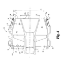
- FIG. 4 is an enlarged illustrative side elevational view of the lean premix dome comprising a portion of the FIG. 2 combustor.
- FIG. 5 is an end view of a centerbody comprising a portion of the FIG. 4 lean premix dome.
- FIG. 6 is another form of the lean premix dome comprising a portion of the combustor of the present invention.
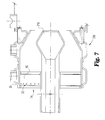
- FIG. 7 is a second alternative form of the lean premix dome comprising a portion of the combustor of the present invention.
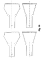
- FIG. 8 is a third alternative form of the lean premix dome comprising a portion of the combustor of the present invention.
- FIG. 9 is an illustrative view of alternative forms of the centerbodies comprising a portion of the lean premix domes of FIG. 6 and 7.
- FIG. 10 is an illustrative view of alternative forms of the centerbodies comprising a portion of the lean premix domes of FIGS. 4 and 8.
- FIG. 1 there is illustrated a natural gas fueled industrial gas turbine engine 10.
- the industrial gas turbine engine illustrated in FIG. 1 is a single shaft model 501-K which is manufactured by Allison Engine Company of Indianapolis, Indiana. It is understood that other gas turbine engines could utilize the present invention.
- An industrial gas turbine engine 10 generally integrates a compressor 11, a combustor 12 and a power turbine 13. It is important to realize that there are a multitude of ways in which the components can be linked together. Additional compressors and turbines could be added with intercoolers connecting between the compressors and reheat combustion chambers could be added between the turbines.
- a combustion system 15 comprises six can type combustion liners 12 that are located in an annulus 16 formed by the outer and inner engine casings. It is understood that other combustion systems are contemplated by this invention.
- Industrial gas turbine engines are used for electric power generations including stand by, continuous, and co-generation applications on land based, oil drilling rigs and ship board installations. Further, industrial gas turbine engines historically have been used to drive compressors in oil and gas recovery, and pipe line service systems as well as providing propulsion power for hydrofoil and conventional vessels.
- FIG. 2 there is illustrated a side elevational view in full section of the preferred embodiment of combustor 12 which forms a portion of combustion system 15.
- the combustor 12 utilizes a dual mode combustion technique to meet pollutant emission requirements and engine operability requirements.
- the two modes of operation are generally referred to as premixed combustion, and pilot-starter diffusion flame combustion.
- a premixed combustion technique mixes the fuel and air prior to delivery into a primary combustion zone 23a within a liner barrel 23.
- fuel is directly injected into the primary combustion zone 23a of combustion liner barrel 23 by a pilot-starter fuel injection system 22.
- the pilot-starter combustion mode operates under a conventional diffusion flame technology that is well known to those skilled in the art.
- premix combustion techniques help to maintain the entire combustor volume at a high degree of uniformity in regards to fuel/air ratio and temperature distribution, and hot spots are minimized or eliminated.
- premixed combustion is not generally available at start up, idle and under low power operation.
- a main fuel system is activated and the engine begins to transfer from the pilot-starter diffusion flame combustor mode to the premix mode of operation.
- the fraction of the total fuel provided through the pilot-starter fuel injection system 22 is reduced while the fraction of the fuel provided by the main fuel system is increased.
- the pilot-starter fuel injection system 22 is shut off and the engine operates under premix combustion exclusively. While the dual mode system is transitioning from one mode of combustion to the other the fraction of fuel provided through the pilot-starter fuel injection system 22 is regulated by a control system that utilizes measured compressor inlet temperature and measured turbine outlet temperature. These parameters are inputs to the control algorithm so that the correspondence between pilot fuel fraction and power level will vary according to local atmospheric conditions and the specifics of the engine installation.
- the combustor 12 consists of a lean premix dome 20, a centerbody 21, a pilot-starter fuel injection system 22, a combustion liner barrel 23, and a combustor turbine transition piece 24.
- air flow exits the compressor 11 in the direction of arrow Y and passes through a diffuser 25 to enter the lean premix dome 20 through an axial swirler 26.
- the lean premix dome 20 is connected to the case of the gas turbine engine by a forward liner support 27.
- dome as used herein is employed to define a chamber of any shape notwithstanding that dome is used in some other contexts to be limited to a hemispherical shape.
- the combustor 12 of the present invention requires that fuel is deliverable to both the premix dome 20 and the primary combustion zone 23a.
- a gas tight connection is necessary between the lean premix dome 20 and the exterior gas supply.
- a flexible bellows 28 is enclosed by a bellow housing 29 which is pressurized to the compressor discharge pressure during operation.
- a main fuel manifold 30 is connected by a fuel passageway to the flexible bellows 28 and ultimately to the external fuel source.
- the main fuel manifold 30 is located between the inner surface 31a of an outer casing 31 of lean premix dome 20 and a lean premix dome liner 99.
- the main fuel manifold 30 is of a substantially flat ring shape and extends around the circumference of the lean premix dome 20.
- the fuel passes radially inward through a passageway formed in each of a plurality of cast vanes 32 that comprise a portion of an axial swirler 26.
- Each of the vanes 32 has a plurality of small apertures 33 formed upstream from the axial midpoint of the vanes for distributing the fuel from the main fuel manifold 30 to the air flowing from the compressor 11 into the axial swirler 26.
- the plurality of apertures 33 are located adjacent the leading edge 100 of each of the vanes 32. It is understood that between the vanes there are passages for the air and fuel mixture to flow through.
- the fixed axial swirler 26 turns the air relative to its point of entry into the axial swirler, and the swirling mixture of fuel and air exiting the axial swirler 26 enters an annular premix chamber 34 that is positioned between the centerbody 21 and the lean premix dome liner 99.
- Premixing chamber 34 is designed and manufactured to have sufficient volume to provide adequate residence time for the mixing of the fuel and air before the mixture exits the lean premix dome 20 into the primary combustion zone 23a.
- the primary combustion zone 23a generally occupies the volume of the combustor liner barrel 23 between the lean premix dome 20 and a plane passing through the combustion liner barrel 23, at a distance 'S' from the lean premix dome 20.
- a converging portion 36 of the premix chamber 34 is formed by the geometric relationship between the centerbody 21 and the lean premix dome liner wall 98.
- the converging portion 36 of the premix chamber 34 functions as a throttling device to accelerate the flowing fuel and air mixture to a velocity sufficient to prevent flashback of a flame into the premix chamber 34. It is preferred that the fluid flow be accelerated to a rate of about 150-200 ft/sec.
- the design of the centerbody 21 and the lean premix dome liner wall 98 are such that there is no flow recirculation within the premix chamber 34 to facilitate stabilization of combustion.
- the swirling fuel air mixture exiting the premix dome 20 is combusted within the combustion liner barrel 23 of the combustor 12.
- the design of the centerbody 21 and premix chamber converging portion 36 has sufficient aerodynamics to purge any flame from the lean premix dome 20, under normal operation, if for some reason flashback does occur. Furthermore, the axial swirler 26 is positioned around the centerbody 21.
- the pilot-starter fuel injection system 22 is connected through the flexible bellow 28a to the external fuel source.
- a pilot fuel manifold 37 is disposed between the outer casing 31 and the premix dome liner 99.
- the pilot fuel manifold 37 is located adjacent the trailing edge 97 of the lean premix dome 20.
- the fuel is natural gas.
- a plurality of equally spaced pilot fuel nozzles 96 are located adjacent the dome liner wall 98. Pilot fuel nozzles 96 spray fuel into the primary combustion zone 23a of combustion liner barrel 23 during engine start up, and during engine operation when the fuel lean premix operation is difficult to achieve because of unstable combustion.
- An igniter plug 39 located in an igniter boss 40, near the pilot nozzles 96, is utilized to ignite the fuel and air mixture within the combustion liner barrel 23.
- FIG. 3 there is illustrated a perspective view of one form of combustor 12 with the lean premix dome 20.
- the substantially cylindrical liner wall 44 of the combustion liner barrel 23 is cooled using either a backside convection cooling or effusion cooling. Both of these designs are generally well known to people skilled in the art and U.S. Patent No. 5,289,686 to Razdan provides added details thereon, and is incorporated herein by reference.
- the effusion cooled design includes providing several thousand small diameter holes 45 that are laser drilled at an acute angle with respect to the wall 44. In the preferred embodiment the holes 45 are formed at an angle of 20 degrees with respect to the liner wall 44.
- the effusion hole pattern is optimized to produce uniform wall temperatures consistent with the design requirements for this liner.
- the inside surface of the combustion liner is coated with a thermal barrier ceramic coating. It is understood that other forms of the present invention utilize backside convention cooling, and that the combustion liner can be utilized without a thermal barrier ceramic coating.
- the distribution of air from the compressor to the combustor is generally in the following ranges: about 50-65% of the air is introduced through the lean premix dome 20; about 0-20% of the air is used for the liner wall cooling; and the balance is introduced through dilution holes such as 47.
- dilution holes such as 47.
- the fixed axial swirler 26 includes twelve airfoil shaped hollow vanes 32 that are attached at their tip 9 to the main fuel manifold 30.
- the vanes 32 because of their airfoil design reduce the total pressure loss through the axial swirler 26, and the vanes 32 enhance the design of the lean premix dome 20 by integrating the radial fuel passageways within the vanes 32.
- the air passing from compressor 11 to the combustor 12 is turned from its direction at the inlet 26a about 70° by the axial swirler 26.
- Each vane 32 is of a variable chord design, thereby imparting a more uniform swirl angle of about 70° to the flowing fuel and air mixture.
- the centerbody 21 has a maximum outside diameter 'L' of 3.124 inches.
- the outer diameter of the lean premix dome 20 exit has a diameter 'm' of 3.856 inches, which gives us a ratio of the centerbody diameter to the lean premix dome exit diameter of about 0.81.
- the diameter of the centerbody 21 at its widest point is on the order of 100% greater than the diameter of the centerbody 21 at its root located at the exit from the vaned swirler 26.
- the smallest amount by which the centerbody 21 widens is about 20% of the root diameter (FIG. 8).
- the maximum diameter of the centerbody 21 is about 35% of the diameter of the combustion liner barrel 23 shown in FIG.
- the diameter of the centerbody tip 21a is about 20% of the diameter of the combustion barrel 23 as illustrated in FIGS. 6 and 7.
- the centerbodies 21 shown in FIGS. 4 and 8 have respective areas that are about 30% and 10% of the area calculated from the diameter of the combustion liner barrel 23. It is understood that in other forms of the present invention alternative combinations of centerbody and lean premix dome exit dimensions are contemplated in order to control the fluid flow. Persons skilled in the art will recognize that it is important to control the exit velocity in order to prevent flashback, and that the geometric relation between the corresponding parts is a method to control the fluid speed.
- the centerbody tip 21a and the premix dome walls 98 are protected from high temperatures by an effusion cooling design similar to that set forth for cooling the combustion liner barrel 23 (FIG. 5).
- the premix dome inside walls 98 and the centerbody tip 21a are coated with a thermal barrier ceramic coating (FIG. 5).
- the thermal barrier ceramic coating 21b and 98b also maintains the walls at a higher temperature than is possible without the coating which helps in reducing the liner wall quenching effect on the reactions involving carbon monoxide and unburned hydrocarbons. By reducing the liner wall quenching effect the emissions of carbon monoxide and unburned hydrocarbons are reduced. It is understood that alternate forms of the present invention utilize the thermal barrier ceramic coating and effusion cooling design as required to meet specific design parameters and that some or all of the components may or may not be coated.
- the pilot-starter fuel injection system 22 utilizes a circumferential pilot ring fuel manifold 37 to provide a steady flow of natural gas to the twelve equally spaced small pilot fuel nozzles 96 located on the outer surface of dome wall 98.
- the pilot fuel nozzles 96 are placed at an angle of 15° to the liner wall and the fuel exit holes 96a are angled at about 45° to the liner wall.
- the acute angle at which the nozzle 96 is oriented relative to the liner wall results in the flame being directed away from the liner wall of the combustion liner barrel 23, thus helping to minimize liner heat distress.
- a single pilot fuel nozzle is located coaxial with and extends longitudinally within the centerbody, and the nozzle dispenses the fuel through the centerbody tip 21a to the primary combustion zone 23a.
- FIGS. 6-8 there are illustrated alternative forms of the lean premix dome 20a, 20b and 20c. It is readily understood by one skilled in the art that these premix domes are substantially similar to the premix dome 20 of the preferred embodiment and therefore can be readily integrated into combustor 12. Further, components and features of the lean premix domes 20a, 20b and 20c are substantially similar to the premix dome 20 and have been given like element numbers.
- premix dome 20a there is illustrated premix dome 20a, and distinctions from premix dome 20 are set forth below.
- the main fuel manifold 30 is connected to ten oval shaped fuel tubes 95 that carry the fuel radially inward from the main fuel manifold 30.
- the oval fuel tubes 95 are equally spaced around the fixed axial swirler 94 and the tubes 95 are located between vane swirler passages that are disposed between adjacent vanes 75.
- Each of the fuel tubes 95 include six small holes 93 having a diameter of about 0.05 inches which distribute the fuel into the air flowing through the axial swirler 94.
- the radial spacing of the fuel holes 93 is designed to distribute the fuel across the moving air path in order to increase the fuel and air mixing efficiency.
- the fuel holes 93 are positioned on the downstream side of the fuel tubes 95 adjacent the vanes 75.
- the fixed axial swirler 94 turns the fluid flow about 60° from the inlet 92 to the entrance into the primary combustion zone.
- the diameter of the lean premix dome exit is about 2.8 inches and the centerbody exit diameter is about 1.0 inches, which gives a ratio of the centerbody to the lean premix dome exit of about 0.35.
- FIG. 7 there is illustrated another form of the lean premix dome 20b that is readily integrated into combustor 12.
- the constant chord length airfoil shaped vanes 90 are integrated into a fixed axial swirler 94.
- the curved vanes 90 are designed to turn the flow of fluid from the compressor about 60° in relation to its direction at the inlet 74.
- Each of the twelve vanes 90 includes six small fuel holes 33 located on each side of the vane (suction and pressure) therefore the axial swirler 94 has vanes with a total of one hundred and forty four fuel exit holes 33.
- a lean premix dome 20c that is substantially identical to lean premix dome 20. Differences between the premix dome 20 and dome 20c include the addition of oval fuel tubes 80 extending radially inward from the main fuel manifold 30 towards the centerbody 21c. In one form of the present invention the fuel tubes extend radially inward about halfway to the wall of the centerbody. It is understood that radial length of the fuel tube can be varied to meet the fuel mixture requirements desired.
- Each of the oval fuel tubes 80 includes three fuel outlet hole 81 formed on each side of the tube at the trailing edge 80a of the oval tube 80.
- the location of the fuel outlet holes 81 on the oval fuel tubes 80 and the opposing fuel holes 33 on the vanes 32 are staggered with respect to each other so that the fuel dispensed from the holes is more evenly spread across the path of the air flow.
- lean premix dome 20c there are a total of two hundred and sixteen fuel holes in the combined oval fuel tube and axial swirler vanes.
- a retrofittable kit is designed to replace the existing combustors within the Allison 501 series engine.
- the kit includes the components discussed herein that are necessary to convert the engine to a dual mode combustion system.
Applications Claiming Priority (2)
| Application Number | Priority Date | Filing Date | Title |
|---|---|---|---|
| US462511 | 1995-06-05 | ||
| US08/462,511 US5813232A (en) | 1995-06-05 | 1995-06-05 | Dry low emission combustor for gas turbine engines |
Publications (3)
| Publication Number | Publication Date |
|---|---|
| EP0747636A2 true EP0747636A2 (de) | 1996-12-11 |
| EP0747636A3 EP0747636A3 (de) | 1998-09-02 |
| EP0747636B1 EP0747636B1 (de) | 2003-03-05 |
Family
ID=23836708
Family Applications (1)
| Application Number | Title | Priority Date | Filing Date |
|---|---|---|---|
| EP96304162A Expired - Lifetime EP0747636B1 (de) | 1995-06-05 | 1996-06-05 | Vormischbrennkammer mit niedrigem Ausstoss für industrielle Gasturbinen |
Country Status (4)
| Country | Link |
|---|---|
| US (2) | US5813232A (de) |
| EP (1) | EP0747636B1 (de) |
| JP (1) | JP3207353B2 (de) |
| DE (1) | DE69626445T2 (de) |
Cited By (13)
| Publication number | Priority date | Publication date | Assignee | Title |
|---|---|---|---|---|
| EP0870989A2 (de) * | 1997-04-10 | 1998-10-14 | European Gas Turbines Limited | Kraftstoffeinspritzanordnung für eine Gasturbinenbrennkammer |
| WO2000012936A1 (de) * | 1998-08-27 | 2000-03-09 | Siemens Aktiengesellschaft | Brenneranordnung mit primärem und sekundärem pilotbrenner |
| EP0935095A3 (de) * | 1998-02-09 | 2000-07-19 | Mitsubishi Heavy Industries, Ltd. | Gasturbinenbrennkammer |
| EP1087178A1 (de) * | 1999-09-23 | 2001-03-28 | Nuovo Pignone Holding S.P.A. | Vormischkammer für Gasturbinen |
| US6561157B2 (en) | 2000-05-08 | 2003-05-13 | Cummins Inc. | Multiple operating mode engine and method of operation |
| EP1323982A1 (de) | 2001-12-20 | 2003-07-02 | Solar Turbines Incorporated | Brennstoffdüse für eine Gasturbine |
| EP1507119A1 (de) * | 2003-08-13 | 2005-02-16 | Siemens Aktiengesellschaft | Brenner und Verfahren zum Betrieb einer Gasturbine |
| EP1645806A1 (de) * | 2004-10-05 | 2006-04-12 | General Electric Company | Verfahren zur Einstellung der Brennstoffeinspritzvorrichtungen für eine Brennstoffdüse einer Gasturbine |
| EP1662202A1 (de) * | 2004-11-30 | 2006-05-31 | Siemens Aktiengesellschaft | Brenner für eine Gasturbinenanlage und Verfahren zum Betreiben eines derartigen Brenners |
| EP2469167A1 (de) | 2010-12-22 | 2012-06-27 | Siemens Aktiengesellschaft | System zum Belüften von flüssigem Brennstoff mit Gas für eine Gasturbine und Verfahren zum Belüften von flüssigem Brennstoff mit Gas für eine Gasturbine |
| EP2487415A1 (de) | 2011-02-10 | 2012-08-15 | Siemens Aktiengesellschaft | Anordnung zur Herstellung von Flüssigbrennstoff und Verfahren zur Herstellung von Flüssigbrennstoff zur Verbrennung |
| US8925323B2 (en) | 2012-04-30 | 2015-01-06 | General Electric Company | Fuel/air premixing system for turbine engine |
| EP2551598B1 (de) * | 2011-07-29 | 2020-11-18 | General Electric Company | Verfahren zum betreiben einer turbomaschine |
Families Citing this family (59)
| Publication number | Priority date | Publication date | Assignee | Title |
|---|---|---|---|---|
| EP0928369B1 (de) | 1996-08-23 | 2006-05-10 | Cummins Inc. | Gemischverdichtende dieselbrennkraftmaschine mit optimaler verbrennungsregelung |
| US6230683B1 (en) | 1997-08-22 | 2001-05-15 | Cummins Engine Company, Inc. | Premixed charge compression ignition engine with optimal combustion control |
| EP0936406B1 (de) | 1998-02-10 | 2004-05-06 | General Electric Company | Brenner mit gleichmässiger Brennstoff/Luft Vormischung zur emissionsarmen Verbrennung |
| EP0983433B1 (de) | 1998-02-23 | 2007-05-16 | Cummins Inc. | Regelung einer verbrennungskraftmaschine mit kompressionszündung und kraftstoff-luftvormischung |
| EP0994300B1 (de) * | 1998-10-14 | 2003-11-26 | ALSTOM (Switzerland) Ltd | Brenner für den Betrieb eines Wärmeerzeugers |
| US6295801B1 (en) * | 1998-12-18 | 2001-10-02 | General Electric Company | Fuel injector bar for gas turbine engine combustor having trapped vortex cavity |
| US6286298B1 (en) * | 1998-12-18 | 2001-09-11 | General Electric Company | Apparatus and method for rich-quench-lean (RQL) concept in a gas turbine engine combustor having trapped vortex cavity |
| US6374615B1 (en) | 2000-01-28 | 2002-04-23 | Alliedsignal, Inc | Low cost, low emissions natural gas combustor |
| US6327860B1 (en) * | 2000-06-21 | 2001-12-11 | Honeywell International, Inc. | Fuel injector for low emissions premixing gas turbine combustor |
| JP2002039533A (ja) * | 2000-07-21 | 2002-02-06 | Mitsubishi Heavy Ind Ltd | 燃焼器、ガスタービン及びジェットエンジン |
| US6363724B1 (en) | 2000-08-31 | 2002-04-02 | General Electric Company | Gas only nozzle fuel tip |
| US6691515B2 (en) | 2002-03-12 | 2004-02-17 | Rolls-Royce Corporation | Dry low combustion system with means for eliminating combustion noise |
| EP2306091A3 (de) | 2002-04-26 | 2012-12-26 | Rolls-Royce Corporation | Brennstoffvormischungsmodul für Gasturbinenbrennkammern |
| EP1389713A1 (de) * | 2002-08-12 | 2004-02-18 | ALSTOM (Switzerland) Ltd | Stromabwärtiger Pilotringbrenner für Vormischbrenner |
| US6832481B2 (en) * | 2002-09-26 | 2004-12-21 | Siemens Westinghouse Power Corporation | Turbine engine fuel nozzle |
| US7284378B2 (en) * | 2004-06-04 | 2007-10-23 | General Electric Company | Methods and apparatus for low emission gas turbine energy generation |
| US20060283181A1 (en) * | 2005-06-15 | 2006-12-21 | Arvin Technologies, Inc. | Swirl-stabilized burner for thermal management of exhaust system and associated method |
| US7302801B2 (en) * | 2004-04-19 | 2007-12-04 | Hamilton Sundstrand Corporation | Lean-staged pyrospin combustor |
| US7059135B2 (en) * | 2004-08-30 | 2006-06-13 | General Electric Company | Method to decrease combustor emissions |
| US20070074518A1 (en) * | 2005-09-30 | 2007-04-05 | Solar Turbines Incorporated | Turbine engine having acoustically tuned fuel nozzle |
| US7703288B2 (en) * | 2005-09-30 | 2010-04-27 | Solar Turbines Inc. | Fuel nozzle having swirler-integrated radial fuel jet |
| US20070119183A1 (en) * | 2005-11-28 | 2007-05-31 | General Electric Company | Gas turbine engine combustor |
| DE102005062079A1 (de) * | 2005-12-22 | 2007-07-12 | Rolls-Royce Deutschland Ltd & Co Kg | Magervormischbrenner mit einer Zerstäuberlippe |
| US20070204624A1 (en) * | 2006-03-01 | 2007-09-06 | Smith Kenneth O | Fuel injector for a turbine engine |
| US8127550B2 (en) | 2007-01-23 | 2012-03-06 | Siemens Energy, Inc. | Anti-flashback features in gas turbine engine combustors |
| US20080267783A1 (en) * | 2007-04-27 | 2008-10-30 | Gilbert Otto Kraemer | Methods and systems to facilitate operating within flame-holding margin |
| US20080276622A1 (en) * | 2007-05-07 | 2008-11-13 | Thomas Edward Johnson | Fuel nozzle and method of fabricating the same |
| GB2453114B (en) * | 2007-09-25 | 2009-08-26 | Siemens Ag | A Swirler for use in a burner of a gas turbine engine |
| JP4959524B2 (ja) | 2007-11-29 | 2012-06-27 | 三菱重工業株式会社 | 燃焼バーナー |
| US9121609B2 (en) * | 2008-10-14 | 2015-09-01 | General Electric Company | Method and apparatus for introducing diluent flow into a combustor |
| US20100089020A1 (en) * | 2008-10-14 | 2010-04-15 | General Electric Company | Metering of diluent flow in combustor |
| US20100089022A1 (en) * | 2008-10-14 | 2010-04-15 | General Electric Company | Method and apparatus of fuel nozzle diluent introduction |
| US8567199B2 (en) * | 2008-10-14 | 2013-10-29 | General Electric Company | Method and apparatus of introducing diluent flow into a combustor |
| US8113002B2 (en) * | 2008-10-17 | 2012-02-14 | General Electric Company | Combustor burner vanelets |
| US8567197B2 (en) * | 2008-12-31 | 2013-10-29 | General Electric Company | Acoustic damper |
| US8607568B2 (en) * | 2009-05-14 | 2013-12-17 | General Electric Company | Dry low NOx combustion system with pre-mixed direct-injection secondary fuel nozzle |
| CH701905A1 (de) * | 2009-09-17 | 2011-03-31 | Alstom Technology Ltd | Verfahren zum Verbrennen wasserstoffreicher, gasförmiger Brennstoffe in einem Brenner sowie Brenner zur Durchführung des Verfahrens. |
| EP2496880B1 (de) | 2009-11-07 | 2018-12-05 | Ansaldo Energia Switzerland AG | Injektionssystem für einen nachbrenner |
| EP2496883B1 (de) * | 2009-11-07 | 2016-08-10 | Alstom Technology Ltd | Vormischrbrenner für einen gasturbinenbrenner |
| EP2496885B1 (de) | 2009-11-07 | 2019-05-29 | Ansaldo Energia Switzerland AG | Brenner mit einem kühlsystem für erhöhte gasturbineneffizienz |
| WO2011054766A2 (en) | 2009-11-07 | 2011-05-12 | Alstom Technology Ltd | Reheat burner injection system |
| WO2011054757A2 (en) | 2009-11-07 | 2011-05-12 | Alstom Technology Ltd | Reheat burner injection system with fuel lances |
| EP2503241A1 (de) * | 2011-03-22 | 2012-09-26 | Siemens Aktiengesellschaft | Gasturbinenbrenner |
| EP2503244A1 (de) * | 2011-03-22 | 2012-09-26 | Siemens Aktiengesellschaft | Gasturbinenbrenner |
| US9046262B2 (en) * | 2011-06-27 | 2015-06-02 | General Electric Company | Premixer fuel nozzle for gas turbine engine |
| US20140137560A1 (en) * | 2012-11-21 | 2014-05-22 | General Electric Company | Turbomachine with trapped vortex feature |
| US9422867B2 (en) * | 2013-02-06 | 2016-08-23 | General Electric Company | Variable volume combustor with center hub fuel staging |
| US9435539B2 (en) * | 2013-02-06 | 2016-09-06 | General Electric Company | Variable volume combustor with pre-nozzle fuel injection system |
| CA2900654C (en) | 2013-03-07 | 2020-03-31 | Rolls-Royce Corporation | Flexible bellows igniter seal for a gas turbine with a ceramic combustion liner |
| US20150107255A1 (en) * | 2013-10-18 | 2015-04-23 | General Electric Company | Turbomachine combustor having an externally fueled late lean injection (lli) system |
| CN104566472B (zh) * | 2014-12-30 | 2018-06-05 | 北京华清燃气轮机与煤气化联合循环工程技术有限公司 | 一种喷嘴及燃气轮机 |
| CN104566471B (zh) * | 2014-12-30 | 2018-03-23 | 北京华清燃气轮机与煤气化联合循环工程技术有限公司 | 一种喷嘴及设有该喷嘴的燃气轮机 |
| US10352567B2 (en) * | 2015-10-09 | 2019-07-16 | General Electric Company | Fuel-air premixer for a gas turbine |
| ES2870975T3 (es) * | 2016-01-15 | 2021-10-28 | Siemens Energy Global Gmbh & Co Kg | Cámara de combustión para una turbina de gas |
| US10801728B2 (en) * | 2016-12-07 | 2020-10-13 | Raytheon Technologies Corporation | Gas turbine engine combustor main mixer with vane supported centerbody |
| KR102096580B1 (ko) * | 2019-04-01 | 2020-04-03 | 두산중공업 주식회사 | 예혼합 균일성이 향상된 연소기 노즐 및 이를 구비하는 가스터빈용 연소기 |
| US11391460B2 (en) * | 2019-07-16 | 2022-07-19 | Raytheon Technologies Corporation | Effusion cooling for dilution/quench hole edges in combustor liner panels |
| GB201910284D0 (en) * | 2019-07-18 | 2019-09-04 | Rolls Royce Plc | Fuel injector |
| FR3099546B1 (fr) * | 2019-07-29 | 2021-08-06 | Safran Aircraft Engines | Chambre de combustion comportant des systèmes d'injection secondaires injectant de l'air et du carburant directement dans des zones de recirculation de coin, turbomachine la comprenant, et procédé d'alimentation en carburant de celle-ci |
Citations (6)
| Publication number | Priority date | Publication date | Assignee | Title |
|---|---|---|---|---|
| US3788067A (en) * | 1971-02-02 | 1974-01-29 | Secr Defence | Fuel burners |
| FR2206441A1 (de) * | 1972-11-09 | 1974-06-07 | Mitsubishi Heavy Ind Ltd | |
| FR2243332A1 (de) * | 1973-09-10 | 1975-04-04 | Gen Electric | |
| GB2045422A (en) * | 1979-03-27 | 1980-10-29 | Gen Electric | Combustor including a cyclone prechamber and combustion process for gas turbines fired with liquid fuel |
| WO1992007221A1 (en) * | 1990-10-23 | 1992-04-30 | Rolls-Royce Plc | Gasturbine combustion chamber and method of operation thereof |
| US5251447A (en) * | 1992-10-01 | 1993-10-12 | General Electric Company | Air fuel mixer for gas turbine combustor |
Family Cites Families (39)
| Publication number | Priority date | Publication date | Assignee | Title |
|---|---|---|---|---|
| US2447482A (en) * | 1945-04-25 | 1948-08-24 | Westinghouse Electric Corp | Turbine apparatus |
| US4078377A (en) * | 1974-01-28 | 1978-03-14 | Ford Motor Company | Internally vaporizing low emission combustor |
| US3859787A (en) * | 1974-02-04 | 1975-01-14 | Gen Motors Corp | Combustion apparatus |
| GB1547374A (en) * | 1975-12-06 | 1979-06-13 | Rolls Royce | Fuel injection for gas turbine engines |
| US4226083A (en) * | 1978-01-19 | 1980-10-07 | United Technologies Corporation | Method and apparatus for reducing nitrous oxide emissions from combustors |
| US4265085A (en) * | 1979-05-30 | 1981-05-05 | United Technologies Corporation | Radially staged low emission can-annular combustor |
| DE2937631A1 (de) * | 1979-09-18 | 1981-04-02 | Daimler-Benz Ag, 7000 Stuttgart | Brennkammer fuer gasturbinen |
| US4263780A (en) * | 1979-09-28 | 1981-04-28 | General Motors Corporation | Lean prechamber outflow combustor with sets of primary air entrances |
| JPS5741524A (en) * | 1980-08-25 | 1982-03-08 | Hitachi Ltd | Combustion method of gas turbine and combustor for gas turbine |
| US4504211A (en) * | 1982-08-02 | 1985-03-12 | Phillips Petroleum Company | Combination of fuels |
| EP0169431B1 (de) * | 1984-07-10 | 1990-04-11 | Hitachi, Ltd. | Brennkammer für eine Gasturbine |
| US4984429A (en) * | 1986-11-25 | 1991-01-15 | General Electric Company | Impingement cooled liner for dry low NOx venturi combustor |
| CH672541A5 (de) * | 1986-12-11 | 1989-11-30 | Bbc Brown Boveri & Cie | |
| US4746859A (en) * | 1986-12-22 | 1988-05-24 | Sundstrand Corporation | Power and temperature independent magnetic position sensor for a rotor |
| EP0276696B1 (de) * | 1987-01-26 | 1990-09-12 | Siemens Aktiengesellschaft | Hybridbrenner für Vormischbetrieb mit Gas und/oder Öl, insbesondere für Gasturbinenanlagen |
| US5339635A (en) * | 1987-09-04 | 1994-08-23 | Hitachi, Ltd. | Gas turbine combustor of the completely premixed combustion type |
| US4802334A (en) * | 1987-10-05 | 1989-02-07 | United Technologies Corporation | Augmentor fuel system |
| JPH076630B2 (ja) * | 1988-01-08 | 1995-01-30 | 株式会社日立製作所 | ガスタービン燃焼器 |
| EP0358437B1 (de) * | 1988-09-07 | 1995-07-12 | Hitachi, Ltd. | Kraftstoff-Luftvormischvorrichtung für eine Gasturbine |
| DE59000422D1 (de) * | 1989-04-20 | 1992-12-10 | Asea Brown Boveri | Brennkammeranordnung. |
| US5127221A (en) * | 1990-05-03 | 1992-07-07 | General Electric Company | Transpiration cooled throat section for low nox combustor and related process |
| GB9023004D0 (en) * | 1990-10-23 | 1990-12-05 | Rolls Royce Plc | A gas turbine engine combustion chamber and a method of operating a gas turbine engine combustion chamber |
| US5165241A (en) * | 1991-02-22 | 1992-11-24 | General Electric Company | Air fuel mixer for gas turbine combustor |
| FR2673455A1 (fr) * | 1991-02-28 | 1992-09-04 | Snecma | Chambre de combustion a premelange pauvre munie d'une enceinte a contre-courant destinee a stabiliser la flamme du premelange. |
| EP0534685A1 (de) * | 1991-09-23 | 1993-03-31 | General Electric Company | Vormischbrenner mit niedriger NOx-Produktion |
| US5164668A (en) * | 1991-12-06 | 1992-11-17 | Honeywell, Inc. | Angular position sensor with decreased sensitivity to shaft position variability |
| US5263325A (en) * | 1991-12-16 | 1993-11-23 | United Technologies Corporation | Low NOx combustion |
| US5259184A (en) * | 1992-03-30 | 1993-11-09 | General Electric Company | Dry low NOx single stage dual mode combustor construction for a gas turbine |
| US5274991A (en) * | 1992-03-30 | 1994-01-04 | General Electric Company | Dry low NOx multi-nozzle combustion liner cap assembly |
| US5309709A (en) * | 1992-06-25 | 1994-05-10 | Solar Turbines Incorporated | Low emission combustion system for a gas turbine engine |
| US5218824A (en) * | 1992-06-25 | 1993-06-15 | Solar Turbines Incorporated | Low emission combustion nozzle for use with a gas turbine engine |
| US5295352A (en) * | 1992-08-04 | 1994-03-22 | General Electric Company | Dual fuel injector with premixing capability for low emissions combustion |
| US5321947A (en) * | 1992-11-10 | 1994-06-21 | Solar Turbines Incorporated | Lean premix combustion system having reduced combustion pressure oscillation |
| US5289686A (en) * | 1992-11-12 | 1994-03-01 | General Motors Corporation | Low nox gas turbine combustor liner with elliptical apertures for air swirling |
| US5327727A (en) * | 1993-04-05 | 1994-07-12 | General Electric Company | Micro-grooved heat transfer combustor wall |
| US5345768A (en) * | 1993-04-07 | 1994-09-13 | General Electric Company | Dual-fuel pre-mixing burner assembly |
| US5394688A (en) * | 1993-10-27 | 1995-03-07 | Westinghouse Electric Corporation | Gas turbine combustor swirl vane arrangement |
| US5351477A (en) * | 1993-12-21 | 1994-10-04 | General Electric Company | Dual fuel mixer for gas turbine combustor |
| US5435126A (en) * | 1994-03-14 | 1995-07-25 | General Electric Company | Fuel nozzle for a turbine having dual capability for diffusion and premix combustion and methods of operation |
-
1995
- 1995-06-05 US US08/462,511 patent/US5813232A/en not_active Expired - Lifetime
-
1996
- 1996-06-05 EP EP96304162A patent/EP0747636B1/de not_active Expired - Lifetime
- 1996-06-05 JP JP14311796A patent/JP3207353B2/ja not_active Expired - Lifetime
- 1996-06-05 DE DE69626445T patent/DE69626445T2/de not_active Expired - Lifetime
-
1997
- 1997-03-28 US US08/821,361 patent/US5794449A/en not_active Expired - Fee Related
Patent Citations (6)
| Publication number | Priority date | Publication date | Assignee | Title |
|---|---|---|---|---|
| US3788067A (en) * | 1971-02-02 | 1974-01-29 | Secr Defence | Fuel burners |
| FR2206441A1 (de) * | 1972-11-09 | 1974-06-07 | Mitsubishi Heavy Ind Ltd | |
| FR2243332A1 (de) * | 1973-09-10 | 1975-04-04 | Gen Electric | |
| GB2045422A (en) * | 1979-03-27 | 1980-10-29 | Gen Electric | Combustor including a cyclone prechamber and combustion process for gas turbines fired with liquid fuel |
| WO1992007221A1 (en) * | 1990-10-23 | 1992-04-30 | Rolls-Royce Plc | Gasturbine combustion chamber and method of operation thereof |
| US5251447A (en) * | 1992-10-01 | 1993-10-12 | General Electric Company | Air fuel mixer for gas turbine combustor |
Cited By (26)
| Publication number | Priority date | Publication date | Assignee | Title |
|---|---|---|---|---|
| US6216466B1 (en) | 1997-04-10 | 2001-04-17 | European Gas Turbines Limited | Fuel-injection arrangement for a gas turbine combustor |
| EP0870989A3 (de) * | 1997-04-10 | 2000-02-23 | European Gas Turbines Limited | Kraftstoffeinspritzanordnung für eine Gasturbinenbrennkammer |
| EP0870989A2 (de) * | 1997-04-10 | 1998-10-14 | European Gas Turbines Limited | Kraftstoffeinspritzanordnung für eine Gasturbinenbrennkammer |
| GB2324147B (en) * | 1997-04-10 | 2001-09-05 | Europ Gas Turbines Ltd | Fuel-injection arrangement for a gas turbine combuster |
| EP0935095A3 (de) * | 1998-02-09 | 2000-07-19 | Mitsubishi Heavy Industries, Ltd. | Gasturbinenbrennkammer |
| US6209326B1 (en) | 1998-02-09 | 2001-04-03 | Mitsubishi Heavy Industries, Ltd. | Gas turbine combustor |
| US6632084B2 (en) | 1998-08-27 | 2003-10-14 | Siemens Aktiengesellschaft | Burner configuration with primary and secondary pilot burners |
| WO2000012936A1 (de) * | 1998-08-27 | 2000-03-09 | Siemens Aktiengesellschaft | Brenneranordnung mit primärem und sekundärem pilotbrenner |
| EP1087178A1 (de) * | 1999-09-23 | 2001-03-28 | Nuovo Pignone Holding S.P.A. | Vormischkammer für Gasturbinen |
| US6363725B1 (en) | 1999-09-23 | 2002-04-02 | Nuovo Pignone Holding S.P.A. | Pre-mixing chamber for gas turbines |
| US6684849B2 (en) | 2000-05-08 | 2004-02-03 | Cummins Inc. | Multiple operating mode engine and method of operation |
| US6561157B2 (en) | 2000-05-08 | 2003-05-13 | Cummins Inc. | Multiple operating mode engine and method of operation |
| US6907870B2 (en) | 2000-05-08 | 2005-06-21 | Cummins Inc. | Multiple operating mode engine and method of operation |
| US6655145B2 (en) | 2001-12-20 | 2003-12-02 | Solar Turbings Inc | Fuel nozzle for a gas turbine engine |
| EP1323982A1 (de) | 2001-12-20 | 2003-07-02 | Solar Turbines Incorporated | Brennstoffdüse für eine Gasturbine |
| EP1507119A1 (de) * | 2003-08-13 | 2005-02-16 | Siemens Aktiengesellschaft | Brenner und Verfahren zum Betrieb einer Gasturbine |
| WO2005019733A1 (de) * | 2003-08-13 | 2005-03-03 | Siemens Aktiengesellschaft | Brenner und verfahren zum betrieb einer gasturbine |
| US7654090B2 (en) | 2003-08-13 | 2010-02-02 | Siemens Aktiengesellschaft | Burner and method for operating a gas turbine |
| EP1645806A1 (de) * | 2004-10-05 | 2006-04-12 | General Electric Company | Verfahren zur Einstellung der Brennstoffeinspritzvorrichtungen für eine Brennstoffdüse einer Gasturbine |
| EP1662202A1 (de) * | 2004-11-30 | 2006-05-31 | Siemens Aktiengesellschaft | Brenner für eine Gasturbinenanlage und Verfahren zum Betreiben eines derartigen Brenners |
| EP2469167A1 (de) | 2010-12-22 | 2012-06-27 | Siemens Aktiengesellschaft | System zum Belüften von flüssigem Brennstoff mit Gas für eine Gasturbine und Verfahren zum Belüften von flüssigem Brennstoff mit Gas für eine Gasturbine |
| WO2012084347A2 (en) | 2010-12-22 | 2012-06-28 | Siemens Aktiengesellschaft | Gas turbine and method for oparating said gas turbine |
| EP2487415A1 (de) | 2011-02-10 | 2012-08-15 | Siemens Aktiengesellschaft | Anordnung zur Herstellung von Flüssigbrennstoff und Verfahren zur Herstellung von Flüssigbrennstoff zur Verbrennung |
| WO2012107287A1 (en) | 2011-02-10 | 2012-08-16 | Siemens Aktiengesellschaft | An arrangement for preparation of liquid fuel for combustion and a method of preparing liquid fuel for combustion |
| EP2551598B1 (de) * | 2011-07-29 | 2020-11-18 | General Electric Company | Verfahren zum betreiben einer turbomaschine |
| US8925323B2 (en) | 2012-04-30 | 2015-01-06 | General Electric Company | Fuel/air premixing system for turbine engine |
Also Published As
| Publication number | Publication date |
|---|---|
| DE69626445D1 (de) | 2003-04-10 |
| JP3207353B2 (ja) | 2001-09-10 |
| DE69626445T2 (de) | 2004-01-15 |
| EP0747636B1 (de) | 2003-03-05 |
| JPH09119640A (ja) | 1997-05-06 |
| EP0747636A3 (de) | 1998-09-02 |
| US5794449A (en) | 1998-08-18 |
| US5813232A (en) | 1998-09-29 |
Similar Documents
| Publication | Publication Date | Title |
|---|---|---|
| US5813232A (en) | Dry low emission combustor for gas turbine engines | |
| EP0747635B1 (de) | Magervormischbrenner mit niedrigem NOx-Ausstoss für industrielle Gasturbinen | |
| EP0653040B1 (de) | Zweikraftstoffeinspritzdüse zum gebrauch in einem gasturbinentriebwerk | |
| CN101368739B (zh) | 燃气涡轮发动机内的燃料的燃烧方法和装置 | |
| US7762073B2 (en) | Pilot mixer for mixer assembly of a gas turbine engine combustor having a primary fuel injector and a plurality of secondary fuel injection ports | |
| US5121597A (en) | Gas turbine combustor and methodd of operating the same | |
| US6826913B2 (en) | Airflow modulation technique for low emissions combustors | |
| EP0600041B1 (de) | Emissionsarme brennerdüse für gasturbinenanlage | |
| EP0878665B1 (de) | Emissionsarmes Verbrennungssystem für Gasturbinentriebwerke | |
| JP4134311B2 (ja) | ガスタービン燃焼器 | |
| JP4578800B2 (ja) | タービン内蔵システム及びそのインジェクタ | |
| EP1193449B1 (de) | Ringverwirbelungsanordnung | |
| US4356698A (en) | Staged combustor having aerodynamically separated combustion zones | |
| US5826423A (en) | Dual fuel injection method and apparatus with multiple air blast liquid fuel atomizers | |
| JPH10148334A (ja) | ガスタービンエンジンの二重燃料噴射器の液体パイロット燃料噴射方法と装置 | |
| JP4997018B2 (ja) | 一次燃料噴射器及び複数の二次燃料噴射ポートを有するガスタービンエンジン燃焼器のミキサ組立体のためのパイロットミキサ | |
| US5303554A (en) | Low NOx injector with central air swirling and angled fuel inlets | |
| RU2626887C2 (ru) | Тангенциальная кольцевая камера сгорания с предварительно смешанным топливом и воздухом для использования в газотурбинных двигателях | |
| GB2161914A (en) | Combustion equipment for a gas turbine engine | |
| KR100679596B1 (ko) | 연소기,연소기구조체,및연료및공기혼합튜브 | |
| GB2099978A (en) | Gas turbine engine combustor | |
| GB2451517A (en) | Pilot mixer for mixer assembly of a gas turbine engine combustor having a primary fuel injector and a plurality of secondary fuel injection ports | |
| JP3499004B2 (ja) | ガスタービン燃焼器 | |
| EP4202302A1 (de) | Brennstoffdüse und verwirbler | |
| CA2596789C (en) | Pilot mixer for mixer assembly of a gas turbine engine combustor having a primary fuel injector and a plurality of secondary fuel injection ports |
Legal Events
| Date | Code | Title | Description |
|---|---|---|---|
| PUAI | Public reference made under article 153(3) epc to a published international application that has entered the european phase |
Free format text: ORIGINAL CODE: 0009012 |
|
| AK | Designated contracting states |
Kind code of ref document: A2 Designated state(s): CH DE FR GB LI SE |
|
| PUAL | Search report despatched |
Free format text: ORIGINAL CODE: 0009013 |
|
| AK | Designated contracting states |
Kind code of ref document: A3 Designated state(s): CH DE FR GB LI SE |
|
| 17P | Request for examination filed |
Effective date: 19990219 |
|
| 17Q | First examination report despatched |
Effective date: 20010427 |
|
| RAP1 | Party data changed (applicant data changed or rights of an application transferred) |
Owner name: ROLLS-ROYCE CORPORATION |
|
| GRAG | Despatch of communication of intention to grant |
Free format text: ORIGINAL CODE: EPIDOS AGRA |
|
| GRAG | Despatch of communication of intention to grant |
Free format text: ORIGINAL CODE: EPIDOS AGRA |
|
| GRAH | Despatch of communication of intention to grant a patent |
Free format text: ORIGINAL CODE: EPIDOS IGRA |
|
| GRAH | Despatch of communication of intention to grant a patent |
Free format text: ORIGINAL CODE: EPIDOS IGRA |
|
| GRAA | (expected) grant |
Free format text: ORIGINAL CODE: 0009210 |
|
| AK | Designated contracting states |
Designated state(s): CH DE FR GB LI SE |
|
| REG | Reference to a national code |
Ref country code: GB Ref legal event code: FG4D |
|
| REG | Reference to a national code |
Ref country code: CH Ref legal event code: EP |
|
| REG | Reference to a national code |
Ref country code: SE Ref legal event code: TRGR |
|
| REF | Corresponds to: |
Ref document number: 69626445 Country of ref document: DE Date of ref document: 20030410 Kind code of ref document: P |
|
| REG | Reference to a national code |
Ref country code: CH Ref legal event code: NV Representative=s name: RITSCHER & PARTNER AG PATENTANWAELTE |
|
| ET | Fr: translation filed | ||
| PLBE | No opposition filed within time limit |
Free format text: ORIGINAL CODE: 0009261 |
|
| STAA | Information on the status of an ep patent application or granted ep patent |
Free format text: STATUS: NO OPPOSITION FILED WITHIN TIME LIMIT |
|
| 26N | No opposition filed |
Effective date: 20031208 |
|
| REG | Reference to a national code |
Ref country code: CH Ref legal event code: PCAR Free format text: RITSCHER & PARTNER AG;RESIRAIN 1;8125 ZOLLIKERBERG (CH) |
|
| REG | Reference to a national code |
Ref country code: CH Ref legal event code: PFA Owner name: ROLLS-ROYCE CORPORATION, US Free format text: FORMER OWNER: ROLLS-ROYCE CORPORATION, US |
|
| PGFP | Annual fee paid to national office [announced via postgrant information from national office to epo] |
Ref country code: CH Payment date: 20140627 Year of fee payment: 19 |
|
| PGFP | Annual fee paid to national office [announced via postgrant information from national office to epo] |
Ref country code: SE Payment date: 20140627 Year of fee payment: 19 |
|
| REG | Reference to a national code |
Ref country code: FR Ref legal event code: PLFP Year of fee payment: 20 |
|
| PGFP | Annual fee paid to national office [announced via postgrant information from national office to epo] |
Ref country code: GB Payment date: 20150629 Year of fee payment: 20 Ref country code: DE Payment date: 20150629 Year of fee payment: 20 |
|
| PGFP | Annual fee paid to national office [announced via postgrant information from national office to epo] |
Ref country code: FR Payment date: 20150617 Year of fee payment: 20 |
|
| REG | Reference to a national code |
Ref country code: CH Ref legal event code: PL |
|
| REG | Reference to a national code |
Ref country code: SE Ref legal event code: EUG |
|
| PG25 | Lapsed in a contracting state [announced via postgrant information from national office to epo] |
Ref country code: SE Free format text: LAPSE BECAUSE OF NON-PAYMENT OF DUE FEES Effective date: 20150606 |
|
| PG25 | Lapsed in a contracting state [announced via postgrant information from national office to epo] |
Ref country code: LI Free format text: LAPSE BECAUSE OF NON-PAYMENT OF DUE FEES Effective date: 20150630 Ref country code: CH Free format text: LAPSE BECAUSE OF NON-PAYMENT OF DUE FEES Effective date: 20150630 |
|
| REG | Reference to a national code |
Ref country code: DE Ref legal event code: R071 Ref document number: 69626445 Country of ref document: DE |
|
| REG | Reference to a national code |
Ref country code: GB Ref legal event code: PE20 Expiry date: 20160604 |
|
| PG25 | Lapsed in a contracting state [announced via postgrant information from national office to epo] |
Ref country code: GB Free format text: LAPSE BECAUSE OF EXPIRATION OF PROTECTION Effective date: 20160604 |