EP0936406B1 - Brenner mit gleichmässiger Brennstoff/Luft Vormischung zur emissionsarmen Verbrennung - Google Patents
Brenner mit gleichmässiger Brennstoff/Luft Vormischung zur emissionsarmen Verbrennung Download PDFInfo
- Publication number
- EP0936406B1 EP0936406B1 EP99300964A EP99300964A EP0936406B1 EP 0936406 B1 EP0936406 B1 EP 0936406B1 EP 99300964 A EP99300964 A EP 99300964A EP 99300964 A EP99300964 A EP 99300964A EP 0936406 B1 EP0936406 B1 EP 0936406B1
- Authority
- EP
- European Patent Office
- Prior art keywords
- fuel
- air
- inlet
- premixer
- passage
- Prior art date
- Legal status (The legal status is an assumption and is not a legal conclusion. Google has not performed a legal analysis and makes no representation as to the accuracy of the status listed.)
- Expired - Lifetime
Links
Images


Classifications
-
- F—MECHANICAL ENGINEERING; LIGHTING; HEATING; WEAPONS; BLASTING
- F23—COMBUSTION APPARATUS; COMBUSTION PROCESSES
- F23C—METHODS OR APPARATUS FOR COMBUSTION USING FLUID FUEL OR SOLID FUEL SUSPENDED IN A CARRIER GAS OR AIR
- F23C7/00—Combustion apparatus characterised by arrangements for air supply
- F23C7/002—Combustion apparatus characterised by arrangements for air supply the air being submitted to a rotary or spinning motion
- F23C7/004—Combustion apparatus characterised by arrangements for air supply the air being submitted to a rotary or spinning motion using vanes
-
- F—MECHANICAL ENGINEERING; LIGHTING; HEATING; WEAPONS; BLASTING
- F23—COMBUSTION APPARATUS; COMBUSTION PROCESSES
- F23D—BURNERS
- F23D14/00—Burners for combustion of a gas, e.g. of a gas stored under pressure as a liquid
- F23D14/02—Premix gas burners, i.e. in which gaseous fuel is mixed with combustion air upstream of the combustion zone
-
- F—MECHANICAL ENGINEERING; LIGHTING; HEATING; WEAPONS; BLASTING
- F23—COMBUSTION APPARATUS; COMBUSTION PROCESSES
- F23M—CASINGS, LININGS, WALLS OR DOORS SPECIALLY ADAPTED FOR COMBUSTION CHAMBERS, e.g. FIREBRIDGES; DEVICES FOR DEFLECTING AIR, FLAMES OR COMBUSTION PRODUCTS IN COMBUSTION CHAMBERS; SAFETY ARRANGEMENTS SPECIALLY ADAPTED FOR COMBUSTION APPARATUS; DETAILS OF COMBUSTION CHAMBERS, NOT OTHERWISE PROVIDED FOR
- F23M9/00—Baffles or deflectors for air or combustion products; Flame shields
- F23M9/02—Baffles or deflectors for air or combustion products; Flame shields in air inlets
-
- F—MECHANICAL ENGINEERING; LIGHTING; HEATING; WEAPONS; BLASTING
- F23—COMBUSTION APPARATUS; COMBUSTION PROCESSES
- F23C—METHODS OR APPARATUS FOR COMBUSTION USING FLUID FUEL OR SOLID FUEL SUSPENDED IN A CARRIER GAS OR AIR
- F23C2900/00—Special features of, or arrangements for combustion apparatus using fluid fuels or solid fuels suspended in air; Combustion processes therefor
- F23C2900/07001—Air swirling vanes incorporating fuel injectors
-
- F—MECHANICAL ENGINEERING; LIGHTING; HEATING; WEAPONS; BLASTING
- F23—COMBUSTION APPARATUS; COMBUSTION PROCESSES
- F23D—BURNERS
- F23D2206/00—Burners for specific applications
- F23D2206/10—Turbines
-
- F—MECHANICAL ENGINEERING; LIGHTING; HEATING; WEAPONS; BLASTING
- F23—COMBUSTION APPARATUS; COMBUSTION PROCESSES
- F23D—BURNERS
- F23D2900/00—Special features of, or arrangements for burners using fluid fuels or solid fuels suspended in a carrier gas
- F23D2900/14—Special features of gas burners
- F23D2900/14021—Premixing burners with swirling or vortices creating means for fuel or air
Definitions
- the present invention relates to heavy duty industrial gas turbines and, in particular, to a burner for an industrial gas turbine including a fuel/air premixer enabling high-efficiency operation without producing undesirable air polluting emissions.
- the primary air polluting emissions usually produced by gas turbines burning conventional hydrocarbon fuels are oxides of nitrogen, carbon monoxide, and unburned hydrocarbons. It is well known in the art that oxidation of molecular nitrogen in air breathing engines is highly dependent upon the maximum hot gas temperature in the combustion system reaction zone. The rate of chemical reactions forming oxides of nitrogen (NOx) is an exponential function of temperature. If the temperature of the combustion chamber hot gas is controlled to a sufficiently low level, thermal NOx will not be produced.
- One preferred method of controlling the temperature of the reaction zone of a heat engine combustor below the level at which thermal NOx is formed is to premix fuel and air to a lean mixture prior to combustion.
- the thermal mass of the excess air present in the reaction zone of a lean premixed combustor absorbs heat and reduces the temperature rise of the products of combustion to a level where thermal NOx is not formed.
- the mixture of fuel and air exiting the premixer and entering the reaction zone of the combustor must be very uniform to achieve the desired emissions performance. If regions in the flow field exist where fuel/air mixture strength is significantly richer than average, the products of combustion in these regions will reach a higher temperature than average, and thermal NOx will be formed. This can result in failure to meet NOx emissions objectives depending upon the combination of temperature and residence time. If regions in the flow field exist where the fuel/air mixture strength is significantly leaner than average, then quenching may occur with failure to oxidize hydrocarbons and/or carbon monoxide to equilibrium levels. This can result in failure to meet carbon monoxide (CO) and/or unburned hydrocarbon (UHC) emissions objectives.
- CO carbon monoxide
- UHC unburned hydrocarbon
- WO 98/11383 discloses a premixe burner comprising means for slowing down part of the air stream entering the premixe burner with respect to the other parts of the air stream in order to stabilize the combustion.
- the current invention is an improvement relative to the prior art in that the unique features of the premixer cause it to achieve performance improvements relative to the prior art in all of the problem areas noted above.
- the emissions of oxides of nitrogen (NOx) are to be minimized without compromising carbon monoxide (CO) or unburned hydrocarbon (UHC) emissions performance.
- IFC inlet flow conditioner
- fuel is injected through the surfaces of air foil shaped turning vanes in the premixer swirler in lieu of the conventional fuel injection tubes, spokes or spray bars of prior art.
- Fuel injection through the surfaces of the turning vanes minimizes the disturbance of the flow field and does not generate regions where the flow of fuel/air mixture stagnates or recirculates within the premixer. These regions of flow stagnation and/or recirculation, which are characteristic of the more intrusive, less aerodynamic features of prior art fuel injectors, form locations where flame can anchor in the premixer. Elimination of these regions makes it more difficult for flame to propagate into the premixer and for combustion to be sustained within the premixer.
- radial fuel/air mixture strength distribution control is obtained with two or more independently controllable fuel supplies injected at different locations on the aerodynamic turning vane surfaces.
- the invention combines three aerodynamic design innovations to produce a fuel/air premixer for use in the combustion system of a heavy-duty industrial gas turbine, burning natural gas fuel, which provides exceptional performance in the areas of fuel/air mixture uniformity, flashback resistance, and control of combustion driven dynamic pressure activity.
- the three aerodynamic design innovations are: (1) Inlet air flow conditioning; (2) Fuel injection through the vanes of an air swirler ("swozzle" assembly); and (3) Radial fuel/air concentration distribution profile control.
- An inlet flow conditioner includes a perforated annular shell at the inlet to the fuel/air premixer swirler through which air flowing to the premixer must pass.
- the pattern of perforations in this shell is designed such that a uniform air flow distribution is produced at the swirler inlet annulus in both the radial and circumferential directions.
- the pressure drop of the inlet flow condition allows it to produce the desired swirler inlet air flow uniformity even when a non-uniform flow field exists in the plenum surrounding the burner inlet.
- the swozzle assembly includes a series of preferably air foil shaped turning vanes that impart swirl to the air flow entering via the IFC.
- Each air foil contains internal fuel flow passages that introduce natural gas fuel into the air stream via fuel metering holes, which pass through the walls of the air foil shaped turning vane.
- the purpose of injecting fuel via two separate passages and two sets of injection holes is to provide control over the fuel/air mixture strength distribution in the radial direction.
- optimum radial concentration profiles can be obtained for control of emissions, lean blow out, and combustion driven dynamic pressure activity as machine and combustor load are varied.
- an annular mixing passage Downstream of the swozzle is an annular mixing passage formed between the hub and the shroud. Fuel/air mixing is completed in this passage, and a very uniform mixture is injected into the combustor reaction zone where burning takes place. Emissions generation is minimized because the uniformly lean mixture does not yield local hot zones where NOx is produced.
- a conventional diffusion flame fuel nozzle In the center of the premixer is a conventional diffusion flame fuel nozzle, which is used at low turbine load when the mixture from the premixer becomes too lean to burn.
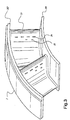
- FIGURE 1 is a cross-section through the burner according to the invention, and FIGURES 2 and 3 show details of the air swirler assembly with fuel injection through the turning vanes or swozzle.
- an air atomized liquid fuel nozzle would be installed in the center of the burner assembly to provide dual fuel capability; however, this liquid fuel nozzle assembly does not form part of the invention and has been omitted from the illustrations for clarity.
- the burner assembly is divided into four regions by function including an inlet flow conditioner 1, an air swirler assembly with natural gas fuel injection (referred to as a swozzle assembly) 2, an annular fuel air mixing passage 3, and a central diffusion flame natural gas fuel nozzle assembly 4.
- the IFC includes an annular flow passage 15 that is bounded by a solid cylindrical inner wall 13 at the inside diameter, a perforated cylindrical outer wall 12 at the outside diameter, and a perforated end cap 11 at the upstream end. In the center of the flow passage 15 is one or more annular turning vanes 14. Premixer air enters the IFC 1 via the perforations in the end cap and cylindrical outer wall.
- the function of the IFC 1 is to prepare the air flow velocity distribution for entry into the premixer.
- the principle of the IFC 1 is based on the concept of backpressuring the premix air before it enters the premixer. This allows for better angular distribution of premix air flow.
- the perforated walls 11, 12 perform the function of backpressuring the system and evenly distributing the flow circumferentially around the IFC annulus 15, whereas the turning vane(s) 14, work in conjunction with the perforated walls to produce proper radial distribution of incoming air in the IFC annulus 15.
- appropriate hole patterns for the perforated walls are selected in conjunction with axial position of the turning vane(s) 14.
- a computer fluid dynamic code is used to calculate flow distribution to determine an appropriate hole pattern for the perforated walls.
- a suitable computer program for this purpose is entitled STAR CD by Adapco of Long Island, New York.
- a bell-mouth shaped transition 26 is used between the IFC and the swozzle.
- the swozzle assembly includes a hub 201 and a shroud 202 connected by a series of air foil shaped turning vanes 23, which impart swirl to the combustion air passing through the premixer.
- Each turning vane 23 contains a primary natural gas fuel supply passage 21 and a secondary natural gas fuel supply passage 22 through the core of the air foil.
- These fuel passages distribute natural gas fuel to primary gas fuel injection holes 24 and secondary gas fuel injection holes 25, which penetrate the wall of the air foil.
- These fuel injection holes may be located on the pressure side, the suction side, or both sides of the turning vanes 23.
- Natural gas fuel enters the swozzle assembly 2 through inlet ports 29 and annular passages 27, 28, which feed the primary and secondary turning vane passages, respectively.
- the natural gas fuel begins mixing with combustion air in the swozzle assembly, and fuel/air mixing is completed in the annular passage 3, which is formed by a swozzle hub extension 31 and a swozzle shroud extension 32.
- the fuel/air mixture After exiting the annular passage 3, the fuel/air mixture enters the combustor reaction zone 5 where combustion takes place.
- the swozzle assembly 2 injects natural gas fuel through the surface of aerodynamic turning vanes (airfoils) 23, the disturbance to the air flow field is minimized.
- the use of this geometry does not create any regions of flow stagnation or separation/recirculation in the premixer after fuel injection into the air stream. Secondary flows are also minimized with this geometry with the result that control of fuel/air mixing and mixture distribution profile is facilitated.
- the flow field remains aerodynamically clean from the region of fuel injection to the premixer discharge into the combustor reaction zone 5.
- the swirl induced by the swozzle 2 causes a central vortex to form with flow recirculation. This stabilizes the flame front in the reaction zone 5.
- FIGURES 2 and 3 show details of the swozzle geometry.
- Radial fuel concentration profile is known to play a significant role in determining the performance of lean premixed dry low emissions combustors, having a significant influence on the combustion driven dynamic pressure activity, the emissions performance and turndown capability.
- the radial profile control provides a means of compensating for natural gas fuel volume flow rate variation due to changes in fuel heating value (composition) and/or supply temperature.
- An additional advantage of this novel fueling scheme is the potential to load reject to the secondary fuel passages since the resulting hub-rich configuration could sustain combustion at a fraction of full load fuel flow.
- a conventional diffusion flame fuel nozzle 4 having a slotted gas tip 42, which receives combustion air from an annular passage 41 and natural gas fuel through gas holes 43.
- the body of this fuel nozzle includes a bellows 44 to compensate for differential thermal expansions between this nozzle and the premixer.
- This fuel nozzle is used during ignition, acceleration, and a low load where the premixer mixture is too lean to burn.
- This diffusion flame fuel nozzle can also provide a pilot flame for the premixer to extend this range of operability.
- a cavity 45 which is designed to receive a liquid fuel nozzle assembly to provide dual fuel capability.
- This invention provides direct active control of the fuel/air radial profile to allow optimal performance over a range of operating conditions. It also allows the possibility of a new load rejection strategy that can help reduce the number of fuel systems and thus the overall system cost.
- supplying fuel to the premixer by two independently controllable flow paths provides a means of controlling the pressure drop across the fuel injection holes.
- This provides another method of controlling dynamic pressure activity because the response of the fuel injection to pressure waves in the premixer can be adjusted to match the air supply response.
- This capability is retained even when variations in fuel supply heating value and/or temperature make it necessary to vary the volume flow of fuel through the injector because the total effective area of the fuel injection holes can be adjusted by varying the fuel flow split between the two flow paths.
- This capability is not available with injectors having a single fixed area fuel flow path, which is typical of prior art.
Claims (8)
- Brenner zur Verwendung in einem Verbrennungssystem von einer Hochleistungs-Industrie-Gasturbine, wobei der Brenner enthält:einen Brennstoff/Luft-Vormischer (2,3) mit einem Lufteinlass, einem Brennstoffeinlass (27, 28, 29) und einem ringförmigen Mischkanal (3), wobei der Brennstoff/Luft-Vormischer (2,3) Brennstoff und Luft in dem ringförmigen Mischkanal zu einem gleichförmigen Gemisch zur Einspritzung in eine Brennkammer-Reaktionzone (5) mischt, wobei der Brennstoff/Luft-Vormischer (2,3) eine Verwirbelungsdüseneinrichtung (2) stromabwärts von dem Lufteinlass aufweist, wobei die Verwirbelungsdüseneinrichtung (2) mehrere Verwirbelungsdüseneinrichtung-Drehschaufeln (23) aufweist, die der ankommenden Luft eine Verwirbelung erteilen, und wobei jede der Verwirbelungsdüseneinrichtung-Drehschaufeln (23) einen inneren Brennstoffströmungskanal (21,22) aufweist, wobei der Brennstoffeinlass (27, 28, 29) Brennstoff in die inneren Brennstoffströmungskanäle einführt, gekennzeichnet durcheinen Einlassströmungs-Konditionierer (1), der an dem Lufteinlass von dem Brennstoff/Luft-Vormischer (2,3) stromaufwärts von dem Brennstoffeinlass (27, 28, 29) angeordnet ist, wobei der Einlassströmungs-Konditionierer (1) eine innere Wand (13) und wenigstens eine äussere Wand (12) aufweist, die dazwischen einen Ringraum bilden, wobei die wenigstens eine
äussere Wand (12) mehrere Löcher aufweist, wobei der Einlassströmungs-Konditionierer (1) ferner wenigstens eine Drehschaufel (14) aufweist, die eine Radial- und
Umfangsverteilung der ankommenden Luft steuert und die ankommende Luft gleichförmig um den Ringraum des Einlassströmungs-Konditionierers (1) verteilt. - Brenner nach Anspruch 1, wobei jede der Drehschaufeln (14) zwei innere Brennstoffströmungskanäle (21, 22) aufweist, die Brennstoff von dem Brennstoffeinalss (27, 28, 29) empfangen, wobei die Brennstoffströmungskanäle (21, 22) Brennstoff in die ankommende Luft einführen.
- Brenner nach Anspruch 2, wobei die Brennstoffströmungskanäle (21, 22) Brennstoff in die ankommende Luft über Brennstoffmesslöcher (24, 25) einführen, die den Brennstoffströmungskanälen (21, 22) entsprechen, wobei die Brennstoffmesslöcher durch entsprechende Wände in den Drehschaufeln (23) hindurchführen.
- Brenner nach Anspruch 1, wobei jede der Drehschaufeln (23) einen primären Brennstoffkanal (21) und einen sekundären Brennstoffkanal (22) aufweist, die Brennstoff einem entsprechenden primären Brennstoff-Einspritzloch (24) bzw. einem sekundären Brennstoff-Einspritzloch (25) zuführen.
- Brenner nach Anspruch 1, wobei die mehreren Löcher in der wenigstens einen äusseren Wand (12) des Einlassströmungs-Konditionierers (1) ein vorbestimmtes Lochmuster aufweisen, das auf einer gewünschten Strömungsverteilung basiert.
- Brenner nach Anspruch 5, wobei der Einlassströmungs-Konditionierer (1) ferner einen ringförmigen Strömungskanal (15) aufweist, der durch die innere Wand (13), die gelöcherte äussere Wand (12) und eine gelöcherte Endkappe (11) begrenzt ist.
- Verfahren zum Vormischen von Brennstoff und Luft in einem Brenner für ein Verbrennungssystem von einer Hochleistungs-Industrie-Gasturbine, wobei der Brenner einen Brennstoff/Luft-Vormischer (2,3) mit einem Lufteinlass, einem Brennstoffeinlass (29) und einem ringförmigen Mischkanal (3) und einen Einlassströmungs-Konditionierer (1) enthält, der an dem Lufteinlass von dem Brennstoff/Luft-Vormischer (2,3) angeordnet ist, wobei der Brennstoff/Luft-Vormischer (2,3) eine Verwirbelungsdüseneinrichtung (2) stromabwärts von dem Lufteinlass aufweist und mehrere Verwirbelungsdüseneinrichtungs-Drehschaufeln (23) enthält, wobei jede der Drehschaufeln (23) einen primären Brennstoffkanal (21) und einen sekundären Brennstoffkanal (22) aufweist, die Brennstoff einem entsprechenden primären Brennstoff-Einspritzloch (24) bzw. einem sekundären Brennstoff-Einspritzloch (25) zuführen, und der Einlassströmungs-Konditionierer (1) eine innere Wand (13) und wenigstens eine äussere Wand (12) aufweist, die dazwischen einen Ringraum (15) bilden, wobei die wenigstens eine äussere Wand (12) mehrere Löcher aufweist, wobei der Einlassströmungs-Konditionierer (1) ferner wenigstens eine ringförmige Drehschaufel aufweist, wobei das Verfahren enthält:(a) Steuern einer Radial- und Umfangsverteilung der ankommenden Luft mit dem Einlassströmungs-Konditionierer (1) stromaufwärts von dem Brennstoffeinlass (29) und gleichförmiges Verteilen der ankommenden Luft um einen Ringraum (16) des Einlassströmungs-Konditionierers (1),(b) Erteilen einer Verwirbelung für die ankommende Luft und(c) Mischen von Brennstoff und Luft zu einem gleichförmigen Gemisch in dem ringförmigen Kanal für ein Einspritzen in eine Brennkammer-Reaktionszone (5) durch unabhängiges Steuern der Brennstoffströmung durch den primären Brennstoffkanal (21) und den sekundären Brennstoffkanal (22).
- Verfahren nach Anspruch 7, wobei der Schritt c) ferner dadurch ausgeführt wird, daß ein radiales Brennstoff/Luft-Konzentrations-Verteilungsprofil von einer Verwirbelungsdüsen-Nabe zu einem Verwirbelungsdüsen-Mantel (202) gesteuert wird.
Applications Claiming Priority (2)
| Application Number | Priority Date | Filing Date | Title |
|---|---|---|---|
| US2108198A | 1998-02-10 | 1998-02-10 | |
| US21081 | 1998-02-10 |
Publications (3)
| Publication Number | Publication Date |
|---|---|
| EP0936406A2 EP0936406A2 (de) | 1999-08-18 |
| EP0936406A3 EP0936406A3 (de) | 2000-01-19 |
| EP0936406B1 true EP0936406B1 (de) | 2004-05-06 |
Family
ID=21802241
Family Applications (1)
| Application Number | Title | Priority Date | Filing Date |
|---|---|---|---|
| EP99300964A Expired - Lifetime EP0936406B1 (de) | 1998-02-10 | 1999-02-10 | Brenner mit gleichmässiger Brennstoff/Luft Vormischung zur emissionsarmen Verbrennung |
Country Status (6)
| Country | Link |
|---|---|
| US (1) | US6438961B2 (de) |
| EP (1) | EP0936406B1 (de) |
| JP (1) | JP4205231B2 (de) |
| KR (1) | KR100550689B1 (de) |
| DE (1) | DE69916911T2 (de) |
| TW (1) | TW425467B (de) |
Cited By (6)
| Publication number | Priority date | Publication date | Assignee | Title |
|---|---|---|---|---|
| CN103216851A (zh) * | 2012-01-18 | 2013-07-24 | 通用电气公司 | 具有弯曲部段的燃烧器喷嘴/预混器 |
| CN103471136A (zh) * | 2012-06-06 | 2013-12-25 | 通用电气公司 | 具有燃料预混器的燃烧器组件 |
| CN104048323A (zh) * | 2013-03-15 | 2014-09-17 | 通用电气公司 | 包括带有燃料喷嘴外壳的多管燃料喷嘴的系统 |
| DE102014105166B3 (de) * | 2014-03-12 | 2015-08-06 | Max Weishaupt Gmbh | Drallerzeuger für einen Brenner sowie damit versehene Mischeinrichtung und damit versehener Brenner |
| CN108474557A (zh) * | 2016-01-05 | 2018-08-31 | 索拉透平公司 | 具有双主燃料喷射的燃料喷射器 |
| CN109099460A (zh) * | 2017-06-20 | 2018-12-28 | 中国航发商用航空发动机有限责任公司 | 一种进气面积调节装置和燃烧室 |
Families Citing this family (221)
| Publication number | Priority date | Publication date | Assignee | Title |
|---|---|---|---|---|
| WO2000019081A2 (en) * | 1998-08-17 | 2000-04-06 | Ramgen Power Systems, Inc. | Fuel supply and fuel - air mixing for a ram jet combustor |
| JP2002031343A (ja) * | 2000-07-13 | 2002-01-31 | Mitsubishi Heavy Ind Ltd | 燃料噴出部材、バーナ、燃焼器の予混合ノズル、燃焼器、ガスタービン及びジェットエンジン |
| JP4508474B2 (ja) * | 2001-06-07 | 2010-07-21 | 三菱重工業株式会社 | 燃焼器 |
| US6655145B2 (en) * | 2001-12-20 | 2003-12-02 | Solar Turbings Inc | Fuel nozzle for a gas turbine engine |
| ITMI20012780A1 (it) * | 2001-12-21 | 2003-06-21 | Nuovo Pignone Spa | Dispositivo di iniezione principale di combustibile liquido per camera di combustione singola dotata di camera di pre-miscelamento di una tu |
| AU2003225181A1 (en) * | 2002-04-26 | 2003-11-10 | Rolls-Royce Corporation | Fuel premixing module for gas turbine engine combustor |
| EP1394471A1 (de) * | 2002-09-02 | 2004-03-03 | Siemens Aktiengesellschaft | Brenner |
| US6786047B2 (en) | 2002-09-17 | 2004-09-07 | Siemens Westinghouse Power Corporation | Flashback resistant pre-mix burner for a gas turbine combustor |
| US6848260B2 (en) | 2002-09-23 | 2005-02-01 | Siemens Westinghouse Power Corporation | Premixed pilot burner for a combustion turbine engine |
| US6832481B2 (en) * | 2002-09-26 | 2004-12-21 | Siemens Westinghouse Power Corporation | Turbine engine fuel nozzle |
| EP1601913A1 (de) * | 2003-03-07 | 2005-12-07 | Alstom Technology Ltd | Vormischbrenner |
| US6837052B2 (en) * | 2003-03-14 | 2005-01-04 | Power Systems Mfg, Llc | Advanced fuel nozzle design with improved premixing |
| EP1507119A1 (de) | 2003-08-13 | 2005-02-16 | Siemens Aktiengesellschaft | Brenner und Verfahren zum Betrieb einer Gasturbine |
| US7284378B2 (en) * | 2004-06-04 | 2007-10-23 | General Electric Company | Methods and apparatus for low emission gas turbine energy generation |
| JP2005306717A (ja) * | 2003-12-09 | 2005-11-04 | Matsushita Electric Ind Co Ltd | 水素生成装置 |
| US7137258B2 (en) * | 2004-06-03 | 2006-11-21 | General Electric Company | Swirler configurations for combustor nozzles and related method |
| US7007477B2 (en) * | 2004-06-03 | 2006-03-07 | General Electric Company | Premixing burner with impingement cooled centerbody and method of cooling centerbody |
| US6993916B2 (en) * | 2004-06-08 | 2006-02-07 | General Electric Company | Burner tube and method for mixing air and gas in a gas turbine engine |
| US7185495B2 (en) | 2004-09-07 | 2007-03-06 | General Electric Company | System and method for improving thermal efficiency of dry low emissions combustor assemblies |
| US7370466B2 (en) * | 2004-11-09 | 2008-05-13 | Siemens Power Generation, Inc. | Extended flashback annulus in a gas turbine combustor |
| EP1662202B1 (de) * | 2004-11-30 | 2016-11-16 | Siemens Aktiengesellschaft | Brenner für eine Gasturbinenanlage |
| US20060156734A1 (en) * | 2005-01-15 | 2006-07-20 | Siemens Westinghouse Power Corporation | Gas turbine combustor |
| JP4476176B2 (ja) | 2005-06-06 | 2010-06-09 | 三菱重工業株式会社 | ガスタービンの予混合燃焼バーナー |
| JP4486549B2 (ja) | 2005-06-06 | 2010-06-23 | 三菱重工業株式会社 | ガスタービンの燃焼器 |
| US7703288B2 (en) * | 2005-09-30 | 2010-04-27 | Solar Turbines Inc. | Fuel nozzle having swirler-integrated radial fuel jet |
| US20070074518A1 (en) * | 2005-09-30 | 2007-04-05 | Solar Turbines Incorporated | Turbine engine having acoustically tuned fuel nozzle |
| US8852638B2 (en) | 2005-09-30 | 2014-10-07 | Durect Corporation | Sustained release small molecule drug formulation |
| US7490471B2 (en) * | 2005-12-08 | 2009-02-17 | General Electric Company | Swirler assembly |
| EP1821035A1 (de) * | 2006-02-15 | 2007-08-22 | Siemens Aktiengesellschaft | Gasturbinenbrenner und Verfahren zum Mischen von Brennstoff und Luft in einem Wirbelbereich eines Gasturbinenbrenners |
| GB2435508B (en) | 2006-02-22 | 2011-08-03 | Siemens Ag | A swirler for use in a burner of a gas turbine engine |
| US20070234735A1 (en) * | 2006-03-28 | 2007-10-11 | Mosbacher David M | Fuel-flexible combustion sytem and method of operation |
| US7762074B2 (en) * | 2006-04-04 | 2010-07-27 | Siemens Energy, Inc. | Air flow conditioner for a combustor can of a gas turbine engine |
| US20070249738A1 (en) * | 2006-04-25 | 2007-10-25 | Haynes Joel M | Premixed partial oxidation syngas generator |
| US7887322B2 (en) * | 2006-09-12 | 2011-02-15 | General Electric Company | Mixing hole arrangement and method for improving homogeneity of an air and fuel mixture in a combustor |
| US20070277530A1 (en) * | 2006-05-31 | 2007-12-06 | Constantin Alexandru Dinu | Inlet flow conditioner for gas turbine engine fuel nozzle |
| US7870736B2 (en) * | 2006-06-01 | 2011-01-18 | Virginia Tech Intellectual Properties, Inc. | Premixing injector for gas turbine engines |
| EP1867925A1 (de) | 2006-06-12 | 2007-12-19 | Siemens Aktiengesellschaft | Brenner |
| EP1892469B1 (de) * | 2006-08-16 | 2011-10-05 | Siemens Aktiengesellschaft | Drallerzeugerkanal und Brenner für eine Gasturbine |
| US7631500B2 (en) * | 2006-09-29 | 2009-12-15 | General Electric Company | Methods and apparatus to facilitate decreasing combustor acoustics |
| US20080078182A1 (en) * | 2006-09-29 | 2008-04-03 | Andrei Tristan Evulet | Premixing device, gas turbines comprising the premixing device, and methods of use |
| US20080078183A1 (en) * | 2006-10-03 | 2008-04-03 | General Electric Company | Liquid fuel enhancement for natural gas swirl stabilized nozzle and method |
| US7908864B2 (en) * | 2006-10-06 | 2011-03-22 | General Electric Company | Combustor nozzle for a fuel-flexible combustion system |
| EP1921376A1 (de) * | 2006-11-08 | 2008-05-14 | Siemens Aktiengesellschaft | Brennstoffeinspritzsystem |
| US8082725B2 (en) | 2007-04-12 | 2011-12-27 | General Electric Company | Electro-dynamic swirler, combustion apparatus and methods using the same |
| US8495982B2 (en) * | 2007-04-19 | 2013-07-30 | Siemens Energy, Inc. | Apparatus for mixing fuel and air in a combustion system |
| US20080267783A1 (en) * | 2007-04-27 | 2008-10-30 | Gilbert Otto Kraemer | Methods and systems to facilitate operating within flame-holding margin |
| US20080276622A1 (en) * | 2007-05-07 | 2008-11-13 | Thomas Edward Johnson | Fuel nozzle and method of fabricating the same |
| US9016601B2 (en) | 2007-05-18 | 2015-04-28 | Siemens Aktiengesellschaft | Fuel distributor |
| EP1992878A1 (de) * | 2007-05-18 | 2008-11-19 | Siemens Aktiengesellschaft | Brennstoffverteiler |
| MX337286B (es) | 2007-05-25 | 2016-02-22 | Indivior Uk Ltd | Formulaciones de transferencia sostenida de compuestos de risperidona. |
| US7861528B2 (en) | 2007-08-21 | 2011-01-04 | General Electric Company | Fuel nozzle and diffusion tip therefor |
| US20090056336A1 (en) | 2007-08-28 | 2009-03-05 | General Electric Company | Gas turbine premixer with radially staged flow passages and method for mixing air and gas in a gas turbine |
| US20090173074A1 (en) * | 2008-01-03 | 2009-07-09 | General Electric Company | Integrated fuel nozzle ifc |
| US8393157B2 (en) * | 2008-01-18 | 2013-03-12 | General Electric Company | Swozzle design for gas turbine combustor |
| US20090241547A1 (en) * | 2008-03-31 | 2009-10-01 | Andrew Luts | Gas turbine fuel injector for lower heating capacity fuels |
| EP2107310A1 (de) * | 2008-04-01 | 2009-10-07 | Siemens Aktiengesellschaft | Brenner |
| EP2107312A1 (de) * | 2008-04-01 | 2009-10-07 | Siemens Aktiengesellschaft | Pilotverbrennkammer in einem Brenner |
| US20090249789A1 (en) * | 2008-04-08 | 2009-10-08 | Baifang Zuo | Burner tube premixer and method for mixing air and gas in a gas turbine engine |
| EP2116768B1 (de) * | 2008-05-09 | 2016-07-27 | Alstom Technology Ltd | Brenner |
| US7578130B1 (en) | 2008-05-20 | 2009-08-25 | General Electric Company | Methods and systems for combustion dynamics reduction |
| US8147121B2 (en) * | 2008-07-09 | 2012-04-03 | General Electric Company | Pre-mixing apparatus for a turbine engine |
| US8186166B2 (en) * | 2008-07-29 | 2012-05-29 | General Electric Company | Hybrid two fuel system nozzle with a bypass connecting the two fuel systems |
| US8112999B2 (en) * | 2008-08-05 | 2012-02-14 | General Electric Company | Turbomachine injection nozzle including a coolant delivery system |
| US8113000B2 (en) * | 2008-09-15 | 2012-02-14 | Siemens Energy, Inc. | Flashback resistant pre-mixer assembly |
| US8490400B2 (en) * | 2008-09-15 | 2013-07-23 | Siemens Energy, Inc. | Combustor assembly comprising a combustor device, a transition duct and a flow conditioner |
| US8661779B2 (en) * | 2008-09-26 | 2014-03-04 | Siemens Energy, Inc. | Flex-fuel injector for gas turbines |
| US20120047902A1 (en) * | 2008-10-15 | 2012-03-01 | Tuthill Richard S | Fuel delivery system for a turbine engine |
| US20100089065A1 (en) * | 2008-10-15 | 2010-04-15 | Tuthill Richard S | Fuel delivery system for a turbine engine |
| US8113002B2 (en) * | 2008-10-17 | 2012-02-14 | General Electric Company | Combustor burner vanelets |
| US8312722B2 (en) * | 2008-10-23 | 2012-11-20 | General Electric Company | Flame holding tolerant fuel and air premixer for a gas turbine combustor |
| US8505304B2 (en) * | 2008-12-01 | 2013-08-13 | General Electric Company | Fuel nozzle detachable burner tube with baffle plate assembly |
| US20100170250A1 (en) * | 2009-01-06 | 2010-07-08 | General Electric Company | Fuel Plenum Vortex Breakers |
| US8104286B2 (en) * | 2009-01-07 | 2012-01-31 | General Electric Company | Methods and systems to enhance flame holding in a gas turbine engine |
| US8434291B2 (en) * | 2009-01-08 | 2013-05-07 | General Electric Company | Systems and methods for detecting a flame in a fuel nozzle of a gas turbine |
| US20100180564A1 (en) * | 2009-01-21 | 2010-07-22 | General Electric Company | Systems and Methods for Mitigating a Flashback Condition in a Premixed Combustor |
| US7942038B2 (en) * | 2009-01-21 | 2011-05-17 | General Electric Company | Systems and methods of monitoring acoustic pressure to detect a flame condition in a gas turbine |
| US20100180599A1 (en) * | 2009-01-21 | 2010-07-22 | Thomas Stephen R | Insertable Pre-Drilled Swirl Vane for Premixing Fuel Nozzle |
| US8297059B2 (en) * | 2009-01-22 | 2012-10-30 | General Electric Company | Nozzle for a turbomachine |
| US9140454B2 (en) * | 2009-01-23 | 2015-09-22 | General Electric Company | Bundled multi-tube nozzle for a turbomachine |
| US8539773B2 (en) * | 2009-02-04 | 2013-09-24 | General Electric Company | Premixed direct injection nozzle for highly reactive fuels |
| US20100192582A1 (en) | 2009-02-04 | 2010-08-05 | Robert Bland | Combustor nozzle |
| US8365535B2 (en) * | 2009-02-09 | 2013-02-05 | General Electric Company | Fuel nozzle with multiple fuel passages within a radial swirler |
| US8851402B2 (en) * | 2009-02-12 | 2014-10-07 | General Electric Company | Fuel injection for gas turbine combustors |
| US8443607B2 (en) * | 2009-02-20 | 2013-05-21 | General Electric Company | Coaxial fuel and air premixer for a gas turbine combustor |
| US8234871B2 (en) * | 2009-03-18 | 2012-08-07 | General Electric Company | Method and apparatus for delivery of a fuel and combustion air mixture to a gas turbine engine using fuel distribution grooves in a manifold disk with discrete air passages |
| US8689559B2 (en) * | 2009-03-30 | 2014-04-08 | General Electric Company | Secondary combustion system for reducing the level of emissions generated by a turbomachine |
| US8333075B2 (en) * | 2009-04-16 | 2012-12-18 | General Electric Company | Gas turbine premixer with internal cooling |
| US8256226B2 (en) * | 2009-04-23 | 2012-09-04 | General Electric Company | Radial lean direct injection burner |
| US8397515B2 (en) * | 2009-04-30 | 2013-03-19 | General Electric Company | Fuel nozzle flashback detection |
| US8234872B2 (en) * | 2009-05-01 | 2012-08-07 | General Electric Company | Turbine air flow conditioner |
| US20120031097A1 (en) * | 2009-05-07 | 2012-02-09 | General Electric Company | Multi-premixer fuel nozzle |
| US8522555B2 (en) | 2009-05-20 | 2013-09-03 | General Electric Company | Multi-premixer fuel nozzle support system |
| US20100293956A1 (en) * | 2009-05-21 | 2010-11-25 | General Electric Company | Turbine fuel nozzle having premixer with auxiliary vane |
| US20100319353A1 (en) * | 2009-06-18 | 2010-12-23 | John Charles Intile | Multiple Fuel Circuits for Syngas/NG DLN in a Premixed Nozzle |
| US8387393B2 (en) * | 2009-06-23 | 2013-03-05 | Siemens Energy, Inc. | Flashback resistant fuel injection system |
| US8607569B2 (en) * | 2009-07-01 | 2013-12-17 | General Electric Company | Methods and systems to thermally protect fuel nozzles in combustion systems |
| US20110000215A1 (en) * | 2009-07-01 | 2011-01-06 | General Electric Company | Combustor Can Flow Conditioner |
| US20110023494A1 (en) | 2009-07-28 | 2011-02-03 | General Electric Company | Gas turbine burner |
| EP2295861A1 (de) * | 2009-08-26 | 2011-03-16 | Siemens Aktiengesellschaft | Brenner, insbesondere für Gasturbinen |
| US8371123B2 (en) * | 2009-10-28 | 2013-02-12 | General Electric Company | Apparatus for conditioning airflow through a nozzle |
| RU2506499C2 (ru) * | 2009-11-09 | 2014-02-10 | Дженерал Электрик Компани | Топливные форсунки газовой турбины с противоположными направлениями завихрения |
| US20110107769A1 (en) * | 2009-11-09 | 2011-05-12 | General Electric Company | Impingement insert for a turbomachine injector |
| RU2534189C2 (ru) * | 2010-02-16 | 2014-11-27 | Дженерал Электрик Компани | Камера сгорания для газовой турбины(варианты) и способ эксплуатации газовой турбины |
| US20110225973A1 (en) * | 2010-03-18 | 2011-09-22 | General Electric Company | Combustor with Pre-Mixing Primary Fuel-Nozzle Assembly |
| US8024932B1 (en) | 2010-04-07 | 2011-09-27 | General Electric Company | System and method for a combustor nozzle |
| US8453454B2 (en) | 2010-04-14 | 2013-06-04 | General Electric Company | Coannular oil injection nozzle |
| US8959921B2 (en) | 2010-07-13 | 2015-02-24 | General Electric Company | Flame tolerant secondary fuel nozzle |
| US8800289B2 (en) | 2010-09-08 | 2014-08-12 | General Electric Company | Apparatus and method for mixing fuel in a gas turbine nozzle |
| US8418469B2 (en) | 2010-09-27 | 2013-04-16 | General Electric Company | Fuel nozzle assembly for gas turbine system |
| US8925324B2 (en) | 2010-10-05 | 2015-01-06 | General Electric Company | Turbomachine including a mixing tube element having a vortex generator |
| US8579211B2 (en) | 2011-01-06 | 2013-11-12 | General Electric Company | System and method for enhancing flow in a nozzle |
| US8528839B2 (en) | 2011-01-19 | 2013-09-10 | General Electric Company | Combustor nozzle and method for fabricating the combustor nozzle |
| US9010083B2 (en) | 2011-02-03 | 2015-04-21 | General Electric Company | Apparatus for mixing fuel in a gas turbine |
| US20120240592A1 (en) * | 2011-03-23 | 2012-09-27 | General Electric Company | Combustor with Fuel Nozzle Liner Having Chevron Ribs |
| US8281596B1 (en) | 2011-05-16 | 2012-10-09 | General Electric Company | Combustor assembly for a turbomachine |
| US8794544B2 (en) * | 2011-06-06 | 2014-08-05 | General Electric Company | Combustor nozzle and method for modifying the combustor nozzle |
| US9032703B2 (en) | 2011-06-20 | 2015-05-19 | General Electric Company | Systems and methods for detecting combustor casing flame holding in a gas turbine engine |
| US9046262B2 (en) * | 2011-06-27 | 2015-06-02 | General Electric Company | Premixer fuel nozzle for gas turbine engine |
| US9388985B2 (en) | 2011-07-29 | 2016-07-12 | General Electric Company | Premixing apparatus for gas turbine system |
| US20130036743A1 (en) * | 2011-08-08 | 2013-02-14 | General Electric Company | Turbomachine combustor assembly |
| US20130040254A1 (en) * | 2011-08-08 | 2013-02-14 | General Electric Company | System and method for monitoring a combustor |
| US9506654B2 (en) | 2011-08-19 | 2016-11-29 | General Electric Company | System and method for reducing combustion dynamics in a combustor |
| US8950188B2 (en) | 2011-09-09 | 2015-02-10 | General Electric Company | Turning guide for combustion fuel nozzle in gas turbine and method to turn fuel flow entering combustion chamber |
| US8984887B2 (en) | 2011-09-25 | 2015-03-24 | General Electric Company | Combustor and method for supplying fuel to a combustor |
| US8801428B2 (en) | 2011-10-04 | 2014-08-12 | General Electric Company | Combustor and method for supplying fuel to a combustor |
| US8550809B2 (en) | 2011-10-20 | 2013-10-08 | General Electric Company | Combustor and method for conditioning flow through a combustor |
| US8955329B2 (en) | 2011-10-21 | 2015-02-17 | General Electric Company | Diffusion nozzles for low-oxygen fuel nozzle assembly and method |
| US9188335B2 (en) | 2011-10-26 | 2015-11-17 | General Electric Company | System and method for reducing combustion dynamics and NOx in a combustor |
| US8899975B2 (en) | 2011-11-04 | 2014-12-02 | General Electric Company | Combustor having wake air injection |
| US9267687B2 (en) | 2011-11-04 | 2016-02-23 | General Electric Company | Combustion system having a venturi for reducing wakes in an airflow |
| US9004912B2 (en) | 2011-11-11 | 2015-04-14 | General Electric Company | Combustor and method for supplying fuel to a combustor |
| US8894407B2 (en) | 2011-11-11 | 2014-11-25 | General Electric Company | Combustor and method for supplying fuel to a combustor |
| US9033699B2 (en) | 2011-11-11 | 2015-05-19 | General Electric Company | Combustor |
| US8978384B2 (en) * | 2011-11-23 | 2015-03-17 | General Electric Company | Swirler assembly with compressor discharge injection to vane surface |
| CN103134078B (zh) | 2011-11-25 | 2015-03-25 | 中国科学院工程热物理研究所 | 一种阵列驻涡燃料-空气预混器 |
| US11015808B2 (en) | 2011-12-13 | 2021-05-25 | General Electric Company | Aerodynamically enhanced premixer with purge slots for reduced emissions |
| US20130167541A1 (en) * | 2012-01-03 | 2013-07-04 | Mahesh Bathina | Air-Fuel Premixer for Gas Turbine Combustor with Variable Swirler |
| US9322557B2 (en) | 2012-01-05 | 2016-04-26 | General Electric Company | Combustor and method for distributing fuel in the combustor |
| US20130205799A1 (en) * | 2012-02-15 | 2013-08-15 | Donald Mark Bailey | Outer Fuel Nozzle Inlet Flow Conditioner Interface to End Cap |
| US9341376B2 (en) | 2012-02-20 | 2016-05-17 | General Electric Company | Combustor and method for supplying fuel to a combustor |
| US20130219899A1 (en) | 2012-02-27 | 2013-08-29 | General Electric Company | Annular premixed pilot in fuel nozzle |
| US9052112B2 (en) | 2012-02-27 | 2015-06-09 | General Electric Company | Combustor and method for purging a combustor |
| WO2013128572A1 (ja) * | 2012-02-28 | 2013-09-06 | 三菱重工業株式会社 | 燃焼器及びガスタービン |
| US9121612B2 (en) | 2012-03-01 | 2015-09-01 | General Electric Company | System and method for reducing combustion dynamics in a combustor |
| US8511086B1 (en) | 2012-03-01 | 2013-08-20 | General Electric Company | System and method for reducing combustion dynamics in a combustor |
| US9353949B2 (en) | 2012-04-17 | 2016-05-31 | Siemens Energy, Inc. | Device for improved air and fuel distribution to a combustor |
| US8925323B2 (en) * | 2012-04-30 | 2015-01-06 | General Electric Company | Fuel/air premixing system for turbine engine |
| US9267690B2 (en) | 2012-05-29 | 2016-02-23 | General Electric Company | Turbomachine combustor nozzle including a monolithic nozzle component and method of forming the same |
| US9249734B2 (en) | 2012-07-10 | 2016-02-02 | General Electric Company | Combustor |
| US8904798B2 (en) | 2012-07-31 | 2014-12-09 | General Electric Company | Combustor |
| US9441835B2 (en) * | 2012-10-08 | 2016-09-13 | General Electric Company | System and method for fuel and steam injection within a combustor |
| EP2728260A1 (de) * | 2012-11-06 | 2014-05-07 | Alstom Technology Ltd | Axialverwirbeler |
| US9353950B2 (en) | 2012-12-10 | 2016-05-31 | General Electric Company | System for reducing combustion dynamics and NOx in a combustor |
| RU2618801C2 (ru) | 2013-01-10 | 2017-05-11 | Дженерал Электрик Компани | Топливная форсунка, концевой узел топливной форсунки и газовая турбина |
| US9297535B2 (en) * | 2013-02-25 | 2016-03-29 | General Electric Company | Fuel/air mixing system for fuel nozzle |
| EP2964950B1 (de) | 2013-03-07 | 2019-08-07 | Rolls-Royce Corporation | Gasturbinenmotor mit flexibler balgdichtung für eine zündvorrichtung |
| US9534787B2 (en) | 2013-03-12 | 2017-01-03 | General Electric Company | Micromixing cap assembly |
| US9366439B2 (en) | 2013-03-12 | 2016-06-14 | General Electric Company | Combustor end cover with fuel plenums |
| US9528444B2 (en) | 2013-03-12 | 2016-12-27 | General Electric Company | System having multi-tube fuel nozzle with floating arrangement of mixing tubes |
| US9765973B2 (en) | 2013-03-12 | 2017-09-19 | General Electric Company | System and method for tube level air flow conditioning |
| US9347668B2 (en) | 2013-03-12 | 2016-05-24 | General Electric Company | End cover configuration and assembly |
| US9651259B2 (en) | 2013-03-12 | 2017-05-16 | General Electric Company | Multi-injector micromixing system |
| US9671112B2 (en) | 2013-03-12 | 2017-06-06 | General Electric Company | Air diffuser for a head end of a combustor |
| US9650959B2 (en) * | 2013-03-12 | 2017-05-16 | General Electric Company | Fuel-air mixing system with mixing chambers of various lengths for gas turbine system |
| US9759425B2 (en) | 2013-03-12 | 2017-09-12 | General Electric Company | System and method having multi-tube fuel nozzle with multiple fuel injectors |
| US20140260302A1 (en) * | 2013-03-14 | 2014-09-18 | General Electric Company | DIFFUSION COMBUSTOR FUEL NOZZLE FOR LIMITING NOx EMISSIONS |
| US9291352B2 (en) | 2013-03-15 | 2016-03-22 | General Electric Company | System having a multi-tube fuel nozzle with an inlet flow conditioner |
| US9784452B2 (en) | 2013-03-15 | 2017-10-10 | General Electric Company | System having a multi-tube fuel nozzle with an aft plate assembly |
| US9546789B2 (en) | 2013-03-15 | 2017-01-17 | General Electric Company | System having a multi-tube fuel nozzle |
| US9316397B2 (en) | 2013-03-15 | 2016-04-19 | General Electric Company | System and method for sealing a fuel nozzle |
| US9322559B2 (en) | 2013-04-17 | 2016-04-26 | General Electric Company | Fuel nozzle having swirler vane and fuel injection peg arrangement |
| US9322553B2 (en) | 2013-05-08 | 2016-04-26 | General Electric Company | Wake manipulating structure for a turbine system |
| US9739201B2 (en) | 2013-05-08 | 2017-08-22 | General Electric Company | Wake reducing structure for a turbine system and method of reducing wake |
| EP2808611B1 (de) * | 2013-05-31 | 2015-12-02 | Siemens Aktiengesellschaft | Injektor zum Einbringen eines Brennstoff-Luft-Gemisches in eine Brennkammer |
| US9410704B2 (en) | 2013-06-03 | 2016-08-09 | General Electric Company | Annular strip micro-mixers for turbomachine combustor |
| DE102013214387B4 (de) * | 2013-07-23 | 2020-10-22 | Eberspächer Climate Control Systems GmbH | Einströmelement, insbesondere für einen Verbrennungsluftströmungsweg im Fahrzeugheizgerät |
| US9273868B2 (en) | 2013-08-06 | 2016-03-01 | General Electric Company | System for supporting bundled tube segments within a combustor |
| US9435221B2 (en) | 2013-08-09 | 2016-09-06 | General Electric Company | Turbomachine airfoil positioning |
| EP3055620A4 (de) * | 2013-10-07 | 2017-01-18 | United Technologies Corporation | Brennstoffverdampfer für eine turbinenmotorbrennkammer |
| US9435540B2 (en) | 2013-12-11 | 2016-09-06 | General Electric Company | Fuel injector with premix pilot nozzle |
| US9534788B2 (en) * | 2014-04-03 | 2017-01-03 | General Electric Company | Air fuel premixer for low emissions gas turbine combustor |
| EP2933560B1 (de) | 2014-04-17 | 2017-12-06 | Ansaldo Energia Switzerland AG | Verfahren zur Vormischung von Luft mit gasförmigem Brennstoff und Brenneranordnung zur Durchführung des Verfahrens |
| US9803864B2 (en) * | 2014-06-24 | 2017-10-31 | General Electric Company | Turbine air flow conditioner |
| WO2016059200A1 (en) | 2014-10-17 | 2016-04-21 | Nuovo Pignone Srl | METHOD FOR REDUCING NOx EMISSION IN A GAS TURBINE, AIR FUEL MIXER, GAS TURBINE AND SWIRLER |
| US9714767B2 (en) | 2014-11-26 | 2017-07-25 | General Electric Company | Premix fuel nozzle assembly |
| US10030869B2 (en) | 2014-11-26 | 2018-07-24 | General Electric Company | Premix fuel nozzle assembly |
| JP2016148507A (ja) | 2014-12-30 | 2016-08-18 | ゼネラル・エレクトリック・カンパニイ | ガスタービン燃焼器におけるパイロットノズル |
| US20160186663A1 (en) | 2014-12-30 | 2016-06-30 | General Electric Company | Pilot nozzle in gas turbine combustor |
| US11015809B2 (en) | 2014-12-30 | 2021-05-25 | General Electric Company | Pilot nozzle in gas turbine combustor |
| US9810427B2 (en) | 2015-03-26 | 2017-11-07 | Ansaldo Energia Switzerland AG | Fuel nozzle with hemispherical dome air inlet |
| US9982892B2 (en) | 2015-04-16 | 2018-05-29 | General Electric Company | Fuel nozzle assembly including a pilot nozzle |
| US9803867B2 (en) | 2015-04-21 | 2017-10-31 | General Electric Company | Premix pilot nozzle |
| KR101721057B1 (ko) | 2015-06-18 | 2017-03-29 | 한국생산기술연구원 | 버너 선회류 강도 조절장치 및 그 강도 조절방법 |
| TWI651142B (zh) * | 2015-12-30 | 2019-02-21 | 逢甲大學 | 混氣式電化學微噴射加工方法及其裝置 |
| US20170248318A1 (en) | 2016-02-26 | 2017-08-31 | General Electric Company | Pilot nozzles in gas turbine combustors |
| US10335900B2 (en) | 2016-03-03 | 2019-07-02 | General Electric Company | Protective shield for liquid guided laser cutting tools |
| US10145561B2 (en) | 2016-09-06 | 2018-12-04 | General Electric Company | Fuel nozzle assembly with resonator |
| EP3301368A1 (de) | 2016-09-28 | 2018-04-04 | Siemens Aktiengesellschaft | Drallkörper, brennkammerbaugruppe und gasturbine mit verbessertem kraftstoff-/luftgemisch |
| CN108019774B (zh) | 2016-11-01 | 2019-12-06 | 北京华清燃气轮机与煤气化联合循环工程技术有限公司 | 用于燃气轮机的预混合燃料喷嘴和燃烧室 |
| CN108006695B (zh) | 2016-11-01 | 2019-12-06 | 北京华清燃气轮机与煤气化联合循环工程技术有限公司 | 优化用于燃气轮机的预混合燃料喷嘴的方法 |
| US20180135532A1 (en) * | 2016-11-15 | 2018-05-17 | General Electric Company | Auto-thermal fuel nozzle flow modulation |
| RU2644319C1 (ru) * | 2017-04-27 | 2018-02-08 | Открытое акционерное общество "Научно-исследовательский институт металлургической теплотехники" (ОАО "ВНИИМТ") | Способ подачи газа и воздуха в горелку для сжигания низкокалорийного и загрязненного топлива и устройство для его осуществления |
| US11396888B1 (en) | 2017-11-09 | 2022-07-26 | Williams International Co., L.L.C. | System and method for guiding compressible gas flowing through a duct |
| US11371706B2 (en) | 2017-12-18 | 2022-06-28 | General Electric Company | Premixed pilot nozzle for gas turbine combustor |
| US10941938B2 (en) * | 2018-02-22 | 2021-03-09 | Delavan Inc. | Fuel injectors including gas fuel injection |
| KR102119879B1 (ko) | 2018-03-07 | 2020-06-08 | 두산중공업 주식회사 | 파일럿 연료 분사 장치, 이를 구비한 연료 노즐 및 가스 터빈 |
| KR102065582B1 (ko) | 2018-03-16 | 2020-01-13 | 두산중공업 주식회사 | 가스 터빈 연료 공급 장치, 이를 구비한 연료 노즐 및 가스 터빈 |
| GB201808070D0 (en) | 2018-05-18 | 2018-07-04 | Rolls Royce Plc | Burner |
| TWI662184B (zh) * | 2018-11-22 | 2019-06-11 | 國家中山科學研究院 | 微渦輪多種燃氣使用之高效預混燃氣噴嘴 |
| US10948188B2 (en) | 2018-12-12 | 2021-03-16 | Solar Turbines Incorporated | Fuel injector with perforated plate |
| KR102096580B1 (ko) | 2019-04-01 | 2020-04-03 | 두산중공업 주식회사 | 예혼합 균일성이 향상된 연소기 노즐 및 이를 구비하는 가스터빈용 연소기 |
| US11187414B2 (en) | 2020-03-31 | 2021-11-30 | General Electric Company | Fuel nozzle with improved swirler vane structure |
| KR102322596B1 (ko) | 2020-07-17 | 2021-11-05 | 두산중공업 주식회사 | 연소기용 노즐 어셈블리 및 이를 포함하는 가스터빈 연소기 |
| US11421883B2 (en) | 2020-09-11 | 2022-08-23 | Raytheon Technologies Corporation | Fuel injector assembly with a helical swirler passage for a turbine engine |
| US11754287B2 (en) | 2020-09-11 | 2023-09-12 | Raytheon Technologies Corporation | Fuel injector assembly for a turbine engine |
| US11649964B2 (en) | 2020-12-01 | 2023-05-16 | Raytheon Technologies Corporation | Fuel injector assembly for a turbine engine |
| KR102522144B1 (ko) * | 2021-09-16 | 2023-04-13 | 두산에너빌리티 주식회사 | 연소기용 연료공급 시스템 |
| KR102522143B1 (ko) * | 2021-09-16 | 2023-04-13 | 두산에너빌리티 주식회사 | 연소기용 연료공급 시스템 |
| US11808455B2 (en) | 2021-11-24 | 2023-11-07 | Rtx Corporation | Gas turbine engine combustor with integral fuel conduit(s) |
| CN114484500B (zh) * | 2022-01-27 | 2022-12-20 | 北京航空航天大学 | 匀流套筒及燃烧室头部结构 |
| US11846249B1 (en) | 2022-09-02 | 2023-12-19 | Rtx Corporation | Gas turbine engine with integral bypass duct |
Family Cites Families (27)
| Publication number | Priority date | Publication date | Assignee | Title |
|---|---|---|---|---|
| DE818072C (de) * | 1948-12-05 | 1951-10-22 | Christian Stoll | Gasbrenner mit Vormischung, insbesondere fuer Industrieoefen |
| US2801134A (en) | 1955-06-28 | 1957-07-30 | Gen Electric | Nozzle |
| US3088279A (en) | 1960-08-26 | 1963-05-07 | Gen Electric | Radial flow gas turbine power plant |
| DE1215443B (de) * | 1963-09-12 | 1966-04-28 | Daimler Benz Ag | Brennkammer, insbesondere fuer Gasturbinentriebwerke |
| US3682390A (en) | 1970-05-13 | 1972-08-08 | Lucas Industries Ltd | Liquid atomizing devices |
| GB1444673A (en) * | 1973-03-20 | 1976-08-04 | Nippon Musical Instruments Mfg | Gas burners |
| US4141213A (en) | 1977-06-23 | 1979-02-27 | General Motors Corporation | Pilot flame tube |
| DE3241162A1 (de) | 1982-11-08 | 1984-05-10 | Kraftwerk Union AG, 4330 Mülheim | Vormischbrenner mit integriertem diffusionsbrenner |
| US5285631A (en) * | 1990-02-05 | 1994-02-15 | General Electric Company | Low NOx emission in gas turbine system |
| US5156002A (en) | 1990-03-05 | 1992-10-20 | Rolf J. Mowill | Low emissions gas turbine combustor |
| DE59204270D1 (de) | 1991-04-25 | 1995-12-14 | Siemens Ag | Brenneranordnung, insbesondere für gasturbinen, zur schadstoffarmen verbrennung von kohlegas und anderen brennstoffen. |
| US5235814A (en) | 1991-08-01 | 1993-08-17 | General Electric Company | Flashback resistant fuel staged premixed combustor |
| US5259184A (en) | 1992-03-30 | 1993-11-09 | General Electric Company | Dry low NOx single stage dual mode combustor construction for a gas turbine |
| US5274995A (en) | 1992-04-27 | 1994-01-04 | General Electric Company | Apparatus and method for atomizing water in a combustor dome assembly |
| US5211004A (en) | 1992-05-27 | 1993-05-18 | General Electric Company | Apparatus for reducing fuel/air concentration oscillations in gas turbine combustors |
| US5361586A (en) | 1993-04-15 | 1994-11-08 | Westinghouse Electric Corporation | Gas turbine ultra low NOx combustor |
| US5404711A (en) | 1993-06-10 | 1995-04-11 | Solar Turbines Incorporated | Dual fuel injector nozzle for use with a gas turbine engine |
| JP3335713B2 (ja) | 1993-06-28 | 2002-10-21 | 株式会社東芝 | ガスタービン燃焼器 |
| US5377483A (en) | 1993-07-07 | 1995-01-03 | Mowill; R. Jan | Process for single stage premixed constant fuel/air ratio combustion |
| US5628182A (en) | 1993-07-07 | 1997-05-13 | Mowill; R. Jan | Star combustor with dilution ports in can portions |
| US5572862A (en) | 1993-07-07 | 1996-11-12 | Mowill Rolf Jan | Convectively cooled, single stage, fully premixed fuel/air combustor for gas turbine engine modules |
| US5351477A (en) * | 1993-12-21 | 1994-10-04 | General Electric Company | Dual fuel mixer for gas turbine combustor |
| US5636510A (en) | 1994-05-25 | 1997-06-10 | Westinghouse Electric Corporation | Gas turbine topping combustor |
| US5657632A (en) | 1994-11-10 | 1997-08-19 | Westinghouse Electric Corporation | Dual fuel gas turbine combustor |
| US5813232A (en) | 1995-06-05 | 1998-09-29 | Allison Engine Company, Inc. | Dry low emission combustor for gas turbine engines |
| JP4130475B2 (ja) * | 1996-09-09 | 2008-08-06 | シーメンス アクチエンゲゼルシヤフト | 空気内で燃料を燃焼する装置とその方法 |
| US5816049A (en) | 1997-01-02 | 1998-10-06 | General Electric Company | Dual fuel mixer for gas turbine combustor |
-
1999
- 1999-02-10 KR KR1019990004695A patent/KR100550689B1/ko not_active IP Right Cessation
- 1999-02-10 DE DE69916911T patent/DE69916911T2/de not_active Expired - Lifetime
- 1999-02-10 JP JP03213899A patent/JP4205231B2/ja not_active Expired - Lifetime
- 1999-02-10 EP EP99300964A patent/EP0936406B1/de not_active Expired - Lifetime
- 1999-04-07 TW TW088102064A patent/TW425467B/zh not_active IP Right Cessation
-
2001
- 2001-03-20 US US09/811,764 patent/US6438961B2/en not_active Expired - Lifetime
Cited By (6)
| Publication number | Priority date | Publication date | Assignee | Title |
|---|---|---|---|---|
| CN103216851A (zh) * | 2012-01-18 | 2013-07-24 | 通用电气公司 | 具有弯曲部段的燃烧器喷嘴/预混器 |
| CN103471136A (zh) * | 2012-06-06 | 2013-12-25 | 通用电气公司 | 具有燃料预混器的燃烧器组件 |
| CN104048323A (zh) * | 2013-03-15 | 2014-09-17 | 通用电气公司 | 包括带有燃料喷嘴外壳的多管燃料喷嘴的系统 |
| DE102014105166B3 (de) * | 2014-03-12 | 2015-08-06 | Max Weishaupt Gmbh | Drallerzeuger für einen Brenner sowie damit versehene Mischeinrichtung und damit versehener Brenner |
| CN108474557A (zh) * | 2016-01-05 | 2018-08-31 | 索拉透平公司 | 具有双主燃料喷射的燃料喷射器 |
| CN109099460A (zh) * | 2017-06-20 | 2018-12-28 | 中国航发商用航空发动机有限责任公司 | 一种进气面积调节装置和燃烧室 |
Also Published As
| Publication number | Publication date |
|---|---|
| JP4205231B2 (ja) | 2009-01-07 |
| US6438961B2 (en) | 2002-08-27 |
| TW425467B (en) | 2001-03-11 |
| DE69916911T2 (de) | 2005-04-21 |
| EP0936406A2 (de) | 1999-08-18 |
| US20010052229A1 (en) | 2001-12-20 |
| JPH11337068A (ja) | 1999-12-10 |
| KR100550689B1 (ko) | 2006-02-08 |
| KR19990072562A (ko) | 1999-09-27 |
| EP0936406A3 (de) | 2000-01-19 |
| DE69916911D1 (de) | 2004-06-09 |
Similar Documents
| Publication | Publication Date | Title |
|---|---|---|
| EP0936406B1 (de) | Brenner mit gleichmässiger Brennstoff/Luft Vormischung zur emissionsarmen Verbrennung | |
| US20100319353A1 (en) | Multiple Fuel Circuits for Syngas/NG DLN in a Premixed Nozzle | |
| US6993916B2 (en) | Burner tube and method for mixing air and gas in a gas turbine engine | |
| US5836164A (en) | Gas turbine combustor | |
| US20090056336A1 (en) | Gas turbine premixer with radially staged flow passages and method for mixing air and gas in a gas turbine | |
| US5295352A (en) | Dual fuel injector with premixing capability for low emissions combustion | |
| US5826429A (en) | Catalytic combustor with lean direct injection of gas fuel for low emissions combustion and methods of operation | |
| US7509811B2 (en) | Multi-point staging strategy for low emission and stable combustion | |
| US6301899B1 (en) | Mixer having intervane fuel injection | |
| US8240150B2 (en) | Lean direct injection diffusion tip and related method | |
| US8590311B2 (en) | Pocketed air and fuel mixing tube | |
| JP2954480B2 (ja) | ガスタービン燃焼器 | |
| US6253555B1 (en) | Combustion chamber comprising mixing ducts with fuel injectors varying in number and cross-sectional area | |
| EP3679300B1 (de) | Gasturbinenbrennkammeranordnung mit hohlraum zum erzeugen eines eingeschlossenen wirbels und verfahren zum betreiben einer gasturbinenbrennkammer | |
| US20080078183A1 (en) | Liquid fuel enhancement for natural gas swirl stabilized nozzle and method | |
| US20090249789A1 (en) | Burner tube premixer and method for mixing air and gas in a gas turbine engine | |
| US8256226B2 (en) | Radial lean direct injection burner | |
| KR20100069683A (ko) | 연료의 2차 분사 제어 장치 및 방법 | |
| JP3954138B2 (ja) | 径方向インフローデュアル燃料インジェクタを備えた燃焼器及び燃料/空気混合チューブ | |
| JP2002257346A (ja) | 環状燃焼器を運転するための方法および環状燃焼器 | |
| JPH08135970A (ja) | ガスタービン燃焼器 | |
| JP4440378B2 (ja) | 燃焼器バッフル | |
| JP3826200B2 (ja) | 予混合燃焼器 |
Legal Events
| Date | Code | Title | Description |
|---|---|---|---|
| PUAI | Public reference made under article 153(3) epc to a published international application that has entered the european phase |
Free format text: ORIGINAL CODE: 0009012 |
|
| AK | Designated contracting states |
Kind code of ref document: A2 Designated state(s): CH DE FR GB LI |
|
| AX | Request for extension of the european patent |
Free format text: AL;LT;LV;MK;RO;SI |
|
| PUAL | Search report despatched |
Free format text: ORIGINAL CODE: 0009013 |
|
| AK | Designated contracting states |
Kind code of ref document: A3 Designated state(s): AT BE CH CY DE DK ES FI FR GB GR IE IT LI LU MC NL PT SE |
|
| AX | Request for extension of the european patent |
Free format text: AL;LT;LV;MK;RO;SI |
|
| 17P | Request for examination filed |
Effective date: 20000719 |
|
| AKX | Designation fees paid |
Free format text: CH DE FR GB LI |
|
| 17Q | First examination report despatched |
Effective date: 20020325 |
|
| GRAP | Despatch of communication of intention to grant a patent |
Free format text: ORIGINAL CODE: EPIDOSNIGR1 |
|
| GRAS | Grant fee paid |
Free format text: ORIGINAL CODE: EPIDOSNIGR3 |
|
| GRAA | (expected) grant |
Free format text: ORIGINAL CODE: 0009210 |
|
| AK | Designated contracting states |
Kind code of ref document: B1 Designated state(s): CH DE FR GB LI |
|
| REG | Reference to a national code |
Ref country code: GB Ref legal event code: FG4D |
|
| REG | Reference to a national code |
Ref country code: CH Ref legal event code: EP |
|
| REF | Corresponds to: |
Ref document number: 69916911 Country of ref document: DE Date of ref document: 20040609 Kind code of ref document: P |
|
| REG | Reference to a national code |
Ref country code: CH Ref legal event code: NV Representative=s name: SERVOPATENT GMBH |
|
| ET | Fr: translation filed | ||
| PLBE | No opposition filed within time limit |
Free format text: ORIGINAL CODE: 0009261 |
|
| STAA | Information on the status of an ep patent application or granted ep patent |
Free format text: STATUS: NO OPPOSITION FILED WITHIN TIME LIMIT |
|
| 26N | No opposition filed |
Effective date: 20050208 |
|
| REG | Reference to a national code |
Ref country code: CH Ref legal event code: PFA Owner name: GENERAL ELECTRIC COMPANY Free format text: GENERAL ELECTRIC COMPANY#1 RIVER ROAD#SCHENECTADY, NY 12345 (US) -TRANSFER TO- GENERAL ELECTRIC COMPANY#1 RIVER ROAD#SCHENECTADY, NY 12345 (US) |
|
| REG | Reference to a national code |
Ref country code: FR Ref legal event code: PLFP Year of fee payment: 18 |
|
| REG | Reference to a national code |
Ref country code: FR Ref legal event code: PLFP Year of fee payment: 19 |
|
| REG | Reference to a national code |
Ref country code: FR Ref legal event code: PLFP Year of fee payment: 20 |
|
| PGFP | Annual fee paid to national office [announced via postgrant information from national office to epo] |
Ref country code: CH Payment date: 20180227 Year of fee payment: 20 Ref country code: GB Payment date: 20180227 Year of fee payment: 20 Ref country code: DE Payment date: 20180227 Year of fee payment: 20 |
|
| PGFP | Annual fee paid to national office [announced via postgrant information from national office to epo] |
Ref country code: FR Payment date: 20180227 Year of fee payment: 20 |
|
| REG | Reference to a national code |
Ref country code: DE Ref legal event code: R071 Ref document number: 69916911 Country of ref document: DE |
|
| REG | Reference to a national code |
Ref country code: CH Ref legal event code: PL |
|
| REG | Reference to a national code |
Ref country code: GB Ref legal event code: PE20 Expiry date: 20190209 |
|
| PG25 | Lapsed in a contracting state [announced via postgrant information from national office to epo] |
Ref country code: GB Free format text: LAPSE BECAUSE OF EXPIRATION OF PROTECTION Effective date: 20190209 |