EP2496883B1 - Vormischrbrenner für einen gasturbinenbrenner - Google Patents
Vormischrbrenner für einen gasturbinenbrenner Download PDFInfo
- Publication number
- EP2496883B1 EP2496883B1 EP10773071.5A EP10773071A EP2496883B1 EP 2496883 B1 EP2496883 B1 EP 2496883B1 EP 10773071 A EP10773071 A EP 10773071A EP 2496883 B1 EP2496883 B1 EP 2496883B1
- Authority
- EP
- European Patent Office
- Prior art keywords
- burner
- fuel
- cross
- sectional area
- streamlined
- Prior art date
- Legal status (The legal status is an assumption and is not a legal conclusion. Google has not performed a legal analysis and makes no representation as to the accuracy of the status listed.)
- Active
Links
Images
Classifications
-
- F—MECHANICAL ENGINEERING; LIGHTING; HEATING; WEAPONS; BLASTING
- F23—COMBUSTION APPARATUS; COMBUSTION PROCESSES
- F23R—GENERATING COMBUSTION PRODUCTS OF HIGH PRESSURE OR HIGH VELOCITY, e.g. GAS-TURBINE COMBUSTION CHAMBERS
- F23R3/00—Continuous combustion chambers using liquid or gaseous fuel
- F23R3/02—Continuous combustion chambers using liquid or gaseous fuel characterised by the air-flow or gas-flow configuration
- F23R3/04—Air inlet arrangements
- F23R3/10—Air inlet arrangements for primary air
- F23R3/12—Air inlet arrangements for primary air inducing a vortex
- F23R3/14—Air inlet arrangements for primary air inducing a vortex by using swirl vanes
-
- F—MECHANICAL ENGINEERING; LIGHTING; HEATING; WEAPONS; BLASTING
- F23—COMBUSTION APPARATUS; COMBUSTION PROCESSES
- F23R—GENERATING COMBUSTION PRODUCTS OF HIGH PRESSURE OR HIGH VELOCITY, e.g. GAS-TURBINE COMBUSTION CHAMBERS
- F23R3/00—Continuous combustion chambers using liquid or gaseous fuel
- F23R3/28—Continuous combustion chambers using liquid or gaseous fuel characterised by the fuel supply
- F23R3/286—Continuous combustion chambers using liquid or gaseous fuel characterised by the fuel supply having fuel-air premixing devices
Definitions
- the present invention relates to a burner in particular for a first of a sequential combustion chamber of a gas turbine or a single combustor only, with an injection device for the introduction of at least one gaseous and/or liquid fuel into the burner.
- (S)EV-burners are currently designed for operation on natural gas and oil only.
- the subsequent mixing of the fuel and the oxidizer at the exit of the mixing zone is just sufficient to allow low NOx emissions (mixing quality), to avoid thermo acoustic pulsations and to avoid flashback (residence time).
- the concept shall provide rapid mixing achievable e.g. for highly reactive fuels with acceptable burner pressure drops.
- This invention shall further provide rapid fuel-air mixing occurring in short burner-mixing lengths.
- the improved burner shall be usable in particular (but not exclusively) for high reactivity conditions, i.e. for a situation where high reactivity fuels, specifically MBtu fuels, shall be burned in such a burner.
- the improvement relates to a burner for a single combustion chamber or first combustion chamber of for example a gas turbine, with an injection device for the introduction of at least one gaseous and/or liquid fuel into the burner, wherein the injection device has at least one body which is arranged in the burner with at least one nozzle for introducing the at least one fuel into the burner, wherein the at least one body is located in a first section of the burner with a first cross-sectional area at a leading edge of the at least one body with reference to a main flow direction prevailing in the burner, wherein downstream of said body a mixing zone is located with a second cross-sectional area.
- the cross-sectional area is reduced, such that the first cross-sectional area is larger than the second cross-sectional area.
- the cross-section available for the flow of combustion gases at the leading edge of the at least one body is larger than the cross-section available for the flow of combustion gases in the mixing zone.
- the proposed concept can be applied in the context of annular combustors but also in the context of can-annular combustors wherein individual burner cans feed hot combustion gas into respective individual portions of the arc of the turbine inlet vanes.
- Each can includes a plurality of main burners disposed in a ring around a central pilot burner, as illustrated for example in US 6,082,111 or in EP 1434007 .
- the design preferably features aerodynamically facilitated axial fuel injection with mixing enhancement via small sized vortex generators.
- the premixed burner is designed to operate for increased fuel flexibility without suffering on high NOx emissions or flashback.
- the proposed burner configuration is applicable for both annular and can-annular combustors. Flame stabilization is achieved by pushing the vortex breakdown occurrence to the burner exit.
- the burner velocities, the axial pressure gradient as well as the dimensional in the bodies and optionally arranged vortex generators are varied to control the vortex breakdown to occur near the burner exit.
- the possible range of applications of the proposed burner is broad.
- the burner can be used for gas turbines, for boilers, water heaters, etc. It can be implemented in can-annular, or annular combustors, and it can be operated with multiple or single fuel, or a different variety of fuels (natural gas, H2, Oil, LBTU fuels etc.)
- the second cross-sectional area is at least 10%, more preferably at least 20%, even more preferably at least 30%, smaller than the first cross-sectional area. Typically it is around 40% smaller than the first cross-sectional area.
- the flow cross-sectional area of the burner is continuously reducing, so in the section where the bodies are arranged, the cross-sectional area is continuously reducing.
- the body has a longitudinal extension essentially along the main flow direction, and the flow cross-sectional area of the burner is continuously reducing from the first cross-sectional area at least over a length of the longitudinal extension, preferably over 1 1/2 or twice the length of this longitudinal extension.
- the injection angle is preferably lower than 90° and the injection device injects fuel under this angle lower than 90° with respect to the main flow direction of the air flow.
- the proposed system is particularly suitable for in-line fuel injection.
- the injection device injects fuel essentially along the main flow direction. This allows to have higher reactivity conditions as the fuel is carried downstream very rapidly and it in addition to that allows to use low pressure carrier gas.
- Fuel can thus be injected under an essentially zero angle with respect to the main flow direction of the air flow (full in-line injection) however it can also be injected at a slight inclination with respect to the main flow direction, so for example at an angle thereto of less than 30°, preferably of less than 15°.
- the at least one body is configured as a streamlined body which has a streamlined cross-sectional profile and which extends with a longitudinal direction perpendicularly to or at an inclination to a main flow direction prevailing in the burner, the at least one nozzle having its outlet orifice at or in a trailing edge of the streamlined body.
- the body in accordance with this aspect of the invention has two lateral surfaces (normally at least for one central body essentially parallel to the main flow direction and converging, i.e. inclined for the others). In this case, preferentially upstream of the at least one nozzle on at least one lateral surface there is located at least one vortex generator.
- the gist of this aspect of the invention is to merge the vortex generator aspect and the fuel injection device into one single combined vortex generation and fuel injection device.
- At least one such injection device is located in the first section, preferably at least two such injection devices are located within one burner, even more preferably three such injection devices or flutes are located within one burner.
- the central one is arranged essentially parallel to the main flow of oxidising medium, while the lateral ones are arranged in a converging manner, essentially parallel to sidewalls converging towards the mixing section.
- the vortex generator has an attack angle in the range of 15-40°, preferably in the range of 15-20° and/or a sweep angle in the range of 40-70°, preferably in the range of 55-65°.
- vortex generators as they are disclosed in US 5,80,360 to as well as in US 5,423,608 can be used in the present context, the disclosure of these two documents being specifically incorporated into this disclosure.
- At least two nozzles are arranged at different positions along said trailing edge (in a row with spacings in between), wherein upstream of each of these nozzles at least one vortex generator is located.
- upstream in the context of the vortex generators relative to the nozzles is intending to mean that the vortex generator generates a vortex at the position of the nozzle.
- the vortex generators may also be upstream facing in order to bring the vortices closer to the fuel injection location.
- vortex generators to adjacent nozzles are located at opposite lateral surfaces of the body. Even more preferably more than three, nozzles are arranged along said trailing edge and vortex generators are alternatingly located at the two lateral surfaces.
- each vortex generator there are located at least two nozzles for fuel injection at the trailing edge.
- a further preferred embodiment is characterised in that the streamlined body extends across the entire flow cross section between opposite walls of the burner.
- these opposite walls between which the streamlined bodies extend are parallel, while the sidewalls joining these two parallel walls are converging towards the mixing section. It is however also possible that these opposite walls converge as well, in this case in a side view the streamlined body is have a trapezoidal shape.
- the profile of the streamlined body can be parallel to the main flow direction. It can however also be inclined with respect to the main flow direction at least over a certain part of its longitudinal extension wherein for example the profile of the streamlined body can be rotated or twisted, for example in opposing directions relative to the longitudinal axis on both sides of a longitudinal midpoint, in order to impose a mild swirl on the main flow.
- the vortex generator(s) can also be provided with cooling elements, wherein preferably these cooling elements are effusion/film cooling holes provided in at least one of the surfaces (also possible is internal cooling such as impingement cooling) of the vortex generator.
- the film cooling holes can be fed with air from the carrier gas feed also used for the fuel injection to simplify the setup. Due to the in-line injection of the fuel, lower pressure carrier gas can be used, so the same gas supply can be used for fuel injection and cooling.
- the body can be provided with cooling elements, wherein preferably these cooling elements are given by internal circulation of cooling medium along the sidewalls (also possible is impingement cooling) of the body and/or by film cooling holes, preferably located near the trailing edge.
- the cooling elements can be fed with air from the carrier gas feed also used for the fuel injection.
- the fuel is injected from the nozzle together with a carrier gas stream (typically the fuel is injected centrally and a carrier gas circumferentially encloses the fuel jet), wherein the carrier gas air is low pressure air with a pressure in the range of 10-20 bar, preferably in the range of 16-20 bar.
- a carrier gas stream typically the fuel is injected centrally and a carrier gas circumferentially encloses the fuel jet
- the carrier gas air is low pressure air with a pressure in the range of 10-20 bar, preferably in the range of 16-20 bar.
- a lower pressure can be used for the carrier gas.
- the streamlined body can have a symmetric cross-sectional profile, i.e. one which is mirror symmetric with respect to the central plane of the body (while however this symmetry does not include necessarily also the vortex generators, these may also be mounted asymmetrically on such a symmetric profile).
- the streamlined body can also be arranged centrally in the burner with respect to a width of a flow cross section.
- the streamlined body can be arranged in the burner such that a straight line connecting the trailing edge to a leading edge extends parallel to the main flow direction of the burner.
- a plurality of separate outlet orifices of a plurality of nozzles can be arranged next to one another and arranged at the trailing edge.
- At least one slit-shaped outlet orifice can be, in the sense of a nozzle, arranged at the trailing edge.
- the present invention relates to the use of a burner as defined above for the combustion under high reactivity conditions, preferably for the combustion at high burner inlet temperatures and/or for the combustion of MBtu fuel, normally with a calorific value of 5000-20,000 kJ/kg, preferably 7000-17,000 kJ/kg, more preferably 10,000-15,000 kJ/kg, most preferably such a fuel comprising hydrogen gas.
- the invention relates in particular (but not exclusively) to combustion of fuel air mixtures having lower ignition delay times and higher flame speeds. This is achieved by an integrated approach, which allows higher velocities of the main flow and in turn, a lower residence time of the fuel air mixture in the mixing zone.
- the challenge regarding the fuel injection is twofold with respect to the use of hydrogen rich fuels and fuel air mixtures:
- the present invention in particular it relates to the stabilised propagating flame regime of burners.
- the main goal of this invention is to evolve an improved premixer configuration, wherein the latter two points are addressed.
- the injector is designed to perform
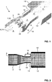
- Figure 1 shows how in the proposed burner the cross-sectional area is reduced to accommodate higher burner velocities in order to help in operating the burner safely for highly reactive fuels and operating conditions.
- the vortex break down location is controlled so as to provide flame stabilization in addition to sudden burner-liner expansion.
- the burner cross-sectional area is varied in particular in section 18 to allow for gradual change in the axial pressure gradient in order to delay the vortex breakdown occurrence.
- figure 1 which is a perspective representation of a burner according to the invention, where the top wall of the burner has been removed, the main flow of oxidizing medium, typically from the compressor, enters along arrow 8 at the inlet side 6 of the actual burner 1.
- a converging portion 18 there are located three injection devices 7, which in this case are structured as streamlined bodies 22. These are arranged within the flow path with essentially parallel longitudinal axes while only the central plane of the central streamlined body is essentially parallel to the flow direction 8 while the outer two streamlined bodies or fluids 22 are inclined with respect to the flow direction 8. More specifically, in the converging portion 18 of the burner, the burner walls 3 are converging and the central planes of the flutes 22 are located essentially parallel to these inclined walls. At the trailing edges 24 of these burners there are located nozzles 15, which inject fuel.
- this converging portion Downstream of this converging portion, the length of which is typically longer than the lengths of the flutes 22, there follows a reduced burner cross sectional area 19.
- the actual mixing space or mixing zone 2 is therefore in this case formed by the portion of the converging portion 18 which is located downstream of the trailing edge 24 of the flutes 22, and by the reduced burner cross sectional area 19.
- the cross section of the flow path In this area 19 the cross section of the flow path is essentially constant. Downstream of this area 19 the flow expands at the transition 13 where the backside wall 13 of the combustion space or combustion chamber 4 is located. At this outlet side 5 or burner exit vortex break down takes place and it is at or just downstream of this where the flame is controlled to be located.
- the combustion chamber 4 is bordered by the combustion chamber walls 12.
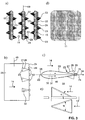
- FIG 2 shows a set-up, where the proposed burner area is reduced considerably. The higher burner velocities help in operating the burner safely at highly reactive conditions.
- a proposed burner is shown with reduced exit cross-section area.
- a fuel injection device according to the invention is located, which is given as a streamlined body 22 extending with its longitudinal direction across the two opposite walls 3 of the burner.
- the two walls 3 converge in a converging portion 18 and narrow down to a reduced burner cross-sectional area 19.
- This defines the mixing space 2 which ends at the outlet side 5 where the mixture of fuel and air enters the combustion chamber or combustion space 4 which is delimited by walls 12.
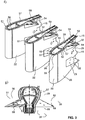
- the first embodiment to this concept is to stagger the vortex generators 23 embedded on the bodies or flutes 22 as shown in Figure 3 .
- the vortex generators 23 are located sufficiently upstream of the fuel injection location to avoid flow recirculations.
- the vortex generator attack and sweep angles are chosen to produce highest circulation rates at a minimum pressure drop.
- attack angle ⁇ in the range of 15-20° and/or a sweep angle ⁇ in the range of 55-65°, for a definition of these angles reference is made to Fig. 3e ), where for an orientation of the vortex generator in the air flow 14 as given in figure 3a ) the definition of the attack angle ⁇ is given in the upper representation which is an elevation view, and the definition of the sweep angle ⁇ is given in the lower representation, which is a top view onto the vortex generator.
- the body 22 is defined by two lateral surfaces 33 joined in a smooth round transition at the leading edge 25 and ending at a small radius/sharp angle at the trailing edge 24 defining the cross-sectional profile 48.
- the vortex generators 23 are located upstream of trailing edge.
- the vortex generators are of triangular shape with a triangular lateral surface 27 converging with the lateral surface 33 upstream of the vortex generator, and two side surfaces 28 essentially perpendicular to a central plane 35 of the body 22.
- the two side's surfaces 28 converge at a trailing edge 29 of the vortex generator 23, and this trailing edge is typically just upstream of the corresponding nozzle 15.
- the lateral surfaces 27 but also the side surfaces 28 maybe provided with effusion/film cooling holes 32.
- the whole body 22 is arranged between and bridging opposite the two walls 3 of the combustor, so along a longitudinal axis 49 essentially perpendicular to the walls 3. Parallel to this longitudinal axis there is, according to this embodiment, the leading edge 25 and the trailing edge 24. It is however also possible that the leading edge 25 and/or the trailing edge are not linear but are rounded.
- the nozzles 15 for fuel injection are located. In this case fuel injection takes place along the injection direction 35 which is parallel to the central plane 35 of the body 22. Fuel as well as carrier air are transported to the nozzles 15 as schematically illustrated by arrows 30 and 31, respectively. Typically the fuel supply is provided by a central tubing, while the carrier air is provided in a flow adjacent to the walls 33 to also provide internal cooling of the structures 22. The carrier airflow is also used for supply of the cooling holes 23. Fuel is injected by generating a central fuel jet along direction 34 enclosed circumferentially by a sleeve of carrier air.
- the swaggering of vortex generators 23 helps in avoiding merging of vortices resulting in preserving very high net longitudinal vorticity.
- the local conditioning of fuel air mixture with vortex generators close to respective fuel jets improves the mixing.
- the overall burner pressure drop is significantly lower for this concept.
- the respective vortex generators produce counter rotating vortices which at a specified location pick up the axially spreading fuel jet.
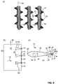
- each body on the trailing side thereof there is located the longitudinal inner fuel tubing 57. It is distanced from the outer wall 59, wherein this distance is maintained by distance keeping elements 53 provided on the inner surface of the outer wall 59.
- branching off tubing extends towards the trailing edge 29 of the body 22.
- the outer walls 59 at the position of these branching off tubings is shaped such as to receive and enclose these branching off tubings forming the actual fuel nozzles with orifices located downstream of the trailing edge 29.
- a cylindrical central element 50 which leads to an annular stream of fuel gas.
- this annular stream of fuel gas at the exit of the nozzle is enclosed by an essentially annular carrier gas stream.
- a carrier air tubing channel 51 extending essentially parallel to the longitudinal inner fuel tubing channel 57. Between the two channels 57 and 51 there is an interspace 55.
- the walls of the carrier air tubing channel 51 facing the outer walls 59 of the body 22 run essentially parallel thereto again distanced therefrom by distancing elements 53.
- cooling holes 56 through which carrier air travelling through channel 51 can penetrate. Air penetrating through these holes 56 impinges onto the inner side of the walls 59 leading to impingement cooling in addition to the convective cooling of the outer walls 59 in this region.
- the vortex generators 23 in a manner such that within the vortex generators cavities 54 are formed which are fluidly connected to the carrier air feed. From this cavity the effusion/film cooling holes 32 are branching off for the cooling of the vortex generators 23. Depending on the exit point of these holes 32 they are inclined with respect to the plane of the surface at the point of exit in order to allow efficient film cooling effects.
- Another embodiment of this concept as shown below in Figure 4 is to direct the fuel at a certain angle (can be increased up to 90°). In this case, the fuel is directed into the vortices and this has shown to improve mixing even further.
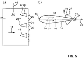
- Another embodiment of this concept is to invert the vortex generators (facing upstream) as shown in figure 5 . This helps in bringing the vortices closer to the fuel injection location with out producing adverse flow recirculations.
- the fuel injection locations can be varied with the vortex generator locations to improve the interaction of vortices with the fuel jet.
- inline injection will involve providing 2 fuel jets (injected at an angle) per VG. This would improve the mixing further since each fuel jet is conditioned by the surrounding vortex.
- Another embodiment involves increasing the number of flutes 22 and completely replaces the current outlet guide vanes of the high-pressure turbine. This provides better mixing and arrest adverse flow variations arising from the high-pressure turbine.
Landscapes
- Engineering & Computer Science (AREA)
- Chemical & Material Sciences (AREA)
- Combustion & Propulsion (AREA)
- Mechanical Engineering (AREA)
- General Engineering & Computer Science (AREA)
- Gas Burners (AREA)
Claims (17)
- Brenner (1) für eine einzelne Brennkammer oder eine erste Brennkammer insbesondere einer Gasturbine, mit einer Einspritzeinrichtung (7) zum Einführen mindestens eines gasförmigen und/oder flüssigen Brennstoffs in den Brenner (1), wobei die Einspritzeinrichtung (7) mindestens einen in dem Brenner (1) angeordneten Körper (22) mit mindestens einer Düse (15) zum Einführen des mindestens einen Brennstoffs in den Brenner (1) hat, wobei der mindestens eine Körper (22) in einem ersten Abschnitt (18) des Brenners (1) mit einer ersten Querschnittsfläche an einer Vorderkante des mindestens einen Körpers (22) in Bezug auf eine in dem Brenner (1) vorherrschende Hauptströmungsrichtung (14) angeordnet ist, wobei stromabwärts des Körpers (22) eine Mischzone (2) mit einer zweiten Querschnittsfläche angeordnet ist und an dem und/oder stromabwärts des Körpers (22) die Querschnittsfläche reduziert ist, sodass die erste Querschnittsfläche größer ist als die zweite Querschnittsfläche, dadurch gekennzeichnet, dass mindestens zwei Düsen (15) an unterschiedlichen Positionen entlang einer Hinterkante (24) des Körpers (22) angeordnet sind, wobei stromaufwärts jeder dieser Düsen (15) mindestens ein Wirbelgenerator (23) angeordnet ist.
- Brenner (1) nach Anspruch 1, wobei die zweite Querschnittsfläche mindestens 10 %, bevorzugter mindestens 20 %, noch bevorzugter mindestens 30 % kleiner ist als die erste Querschnittsfläche.
- Brenner (1) nach einem der vorhergehenden Ansprüche, wobei in dem ersten Abschnitt (18) die Strömungsquerschnittsfläche des Brenners kontinuierlich abnimmt.
- Brenner (1) nach einem der vorhergehenden Ansprüche, wobei der Körper (22) eine Längenausdehnung im Wesentlichen entlang der Hauptströmungsrichtung (14) hat und wobei die Strömungsquerschnittsfläche des Brenners von der ersten Querschnittsfläche mindestens über eine Länge der Längenausdehnung, vorzugsweise über das Zweifache der Länge der Längenausdehnung kontinuierlich abnimmt.
- Brenner (1) nach einem der vorhergehenden Ansprüche, wobei die Einspritzeinrichtung (7) Brennstoff im Wesentlichen entlang der Hauptströmungsrichtung (14) oder in einem Winkel von weniger als 90°, vorzugsweise weniger als 30°, bevorzugter weniger als 15° zu dieser einspritzt.
- Brenner (1) nach einem der vorhergehenden Ansprüche, wobei der mindestens eine Körper als ein stromlinienförmiger Körper (22) konfiguriert ist, der ein stromlinienförmiges Querschnittsprofil (48) hat und der sich mit einer Längsrichtung (49) senkrecht oder mit einer Neigung zu einer in dem Brenner (1) vorherrschenden Hauptströmungsrichtung (14) erstreckt, wobei die mindestens eine Düse (15) ihre Auslassöffnung an oder in einer Hinterkante (24) des stromlinienförmigen Körpers (22) hat, wobei der Körper (22) zwei seitliche Flächen (33) hat und wobei vorzugsweise stromaufwärts der mindestens einen Düse (15) auf mindestens einer seitlichen Fläche (33) mindestens ein Wirbelgenerator (23) angeordnet ist.
- Brenner (1) nach Anspruch 6, wobei der Wirbelgenerator (23) einen Anstellwinkel im Bereich von 15-20° und/oder einen Pfeilwinkel im Bereich von 45-75°, vorzugsweise 55-65° hat.
- Brenner (1) nach einem der vorhergehenden Ansprüche, wobei Wirbelgeneratoren (23) für benachbarte Düsen (15) an entgegengesetzten seitliche Flächen (33) angeordnet sind und wobei bevorzugt mehr als drei Düsen (15) entlang der Hinterkante (24) angeordnet sind und Wirbelgeneratoren (23) abwechselnd an den beiden seitlichen Flächen (33) angeordnet sind.
- Brenner (1) nach einem der vorhergehenden Ansprüche 6-8, wobei stromabwärts jedes Wirbelgenerators (23) mindestens zwei Düsen (15) angeordnet sind.
- Brenner (1) nach einem der vorhergehenden Ansprüche 6-9, wobei der stromlinienförmige Körper (22) sich über den gesamten Strömungsquerschnitt zwischen entgegengesetzten Wänden (3) des Brenners (1) erstreckt.
- Brenner (1) nach einem der vorhergehenden Ansprüche, wobei mindestens zwei Körper (22), vorzugsweise in Form von stromlinienförmigen Körpern, in dem ersten Abschnitt (18) angeordnet sind, wobei bevorzugt, vorzugsweise zwischen 3 stromlinienförmige Körper in dem ersten Abschnitt (18) angeordnet sind, wobei deren Längsachsen (49) im Wesentlichen parallel zueinander angeordnet sind und wobei deren Mittelebenen (35) zu dem Mischabschnitt (2) hin konvergierend angeordnet sind.
- Brenner (1) nach einem der vorhergehenden Ansprüche, wobei mindestens ein Körper (22) ein stromlinienförmiger Körper (22) ist und wobei das Profil des stromlinienförmigen Körpers (22) in Bezug auf die Hauptströmungsrichtung (14) zumindest über einen gewissen Teil seiner Längenausdehnung geneigt ist, wobei vorzugsweise das Profil des stromlinienförmigen Körpers (22) in Bezug auf die Längsachse auf beiden Seiten eines Mittelpunkts in Längsrichtung gedreht oder verwunden ist, um der Hauptströmung einen leichten Wirbel zu erteilen.
- Brenner (1) nach einem der vorhergehenden Ansprüche 6-10, wobei der Wirbelgenerator (23) mit Kühlelementen (32) versehen ist, wobei vorzugsweise diese Kühlelemente (32) Filmkühlungslöcher sind, die in mindestens einer der Oberflächen (27, 28) des Wirbelgenerators (23) vorgesehen sind, und wobei noch bevorzugter die Filmkühlungslöcher (32) mit Luft aus der Trägergaseinspeisung (31) gespeist werden, die auch für die Brennstoffeinspritzung verwendet wird.
- Brenner (1) nach einem der vorhergehenden Ansprüche, wobei der Körper (22) mit Kühlelementen versehen ist, wobei vorzugsweise diese Kühlelemente durch die interne Zirkulation von Kühlmedium entlang den Seitenwänden (33) des Körpers (22) und/oder durch Filmkühlungslöcher gegeben sind, die vorzugsweise nahe an der Hinterkante (24) angeordnet sind, und wobei höchst bevorzugt die Kühlelemente mit Luft aus der Trägergaseinspeisung (31) gespeist werden, die ebenfalls für die Brennstoffeinspritzung verwendet wird.
- Brenner (1) nach einem der vorhergehenden Ansprüche, wobei der Brennstoff aus der Düse (15) zusammen mit einem Trägergasstrom eingespritzt wird, und wobei die Trägergasluft Niederdruckluft mit einem Druck im Bereich von 10-25 bar, vorzugsweise im Bereich von 16-20 bar ist.
- Brenner nach einem der vorhergehenden Ansprüche, wobei der Körper (22) ein stromlinienförmiger Körper (22) ist und wobei der stromlinienförmige Körper (22) ein Querschnittsprofil (48) hat, welches in Bezug auf die Mittelebene (35) des Körpers (22) spiegelsymmetrisch ist.
- Verwendung eines Brenners (1) nach einem der vorhergehenden Ansprüche für die Verbrennung unter Bedingungen hoher Reaktivität, vorzugsweise für die Verbrennung bei hohen Brennereinlasstemperaturen und/oder für die Verbrennung von MBtu-Brennstoff.
Applications Claiming Priority (2)
| Application Number | Priority Date | Filing Date | Title |
|---|---|---|---|
| CH18902009 | 2009-11-07 | ||
| PCT/EP2010/066535 WO2011054771A2 (en) | 2009-11-07 | 2010-10-29 | Premixed burner for a gas turbine combustor |
Publications (2)
| Publication Number | Publication Date |
|---|---|
| EP2496883A2 EP2496883A2 (de) | 2012-09-12 |
| EP2496883B1 true EP2496883B1 (de) | 2016-08-10 |
Family
ID=42060508
Family Applications (1)
| Application Number | Title | Priority Date | Filing Date |
|---|---|---|---|
| EP10773071.5A Active EP2496883B1 (de) | 2009-11-07 | 2010-10-29 | Vormischrbrenner für einen gasturbinenbrenner |
Country Status (3)
| Country | Link |
|---|---|
| US (1) | US8490398B2 (de) |
| EP (1) | EP2496883B1 (de) |
| WO (1) | WO2011054771A2 (de) |
Cited By (1)
| Publication number | Priority date | Publication date | Assignee | Title |
|---|---|---|---|---|
| DE102023203273A1 (de) * | 2023-04-11 | 2024-10-17 | Siemens Energy Global GmbH & Co. KG | Verbessertes Brennerteil und Brenner mit einem solchen Brennerteil |
Families Citing this family (20)
| Publication number | Priority date | Publication date | Assignee | Title |
|---|---|---|---|---|
| RU2550370C2 (ru) * | 2011-05-11 | 2015-05-10 | Альстом Текнолоджи Лтд | Центробежная форсунка с выступающими частями |
| EP2700879B1 (de) * | 2012-08-24 | 2019-03-27 | Ansaldo Energia Switzerland AG | Verfahren zum mischen einer verdünnungsluft in einem sequenziellen verbrennungssystem einer gasturbine und sequentielles verbrennungssystem für eine gasturbine mit verdünnungsluftinjektor |
| US9335050B2 (en) * | 2012-09-26 | 2016-05-10 | United Technologies Corporation | Gas turbine engine combustor |
| CA2830031C (en) * | 2012-10-23 | 2016-03-15 | Alstom Technology Ltd. | Burner for a can combustor |
| DE102015003920A1 (de) * | 2014-09-25 | 2016-03-31 | Dürr Systems GmbH | Brennerkopf eines Brenners und Gasturbine mit einem solchen Brenner |
| EP3023696B1 (de) * | 2014-11-20 | 2019-08-28 | Ansaldo Energia Switzerland AG | Nockenlanze für eine Gasturbinenbrennkammer |
| EP3026344B1 (de) | 2014-11-26 | 2019-05-22 | Ansaldo Energia Switzerland AG | Brenner einer Gasturbine |
| EP3073198B1 (de) | 2015-03-27 | 2019-12-25 | Ansaldo Energia Switzerland AG | Integriertes zweikraftstofffördersystem |
| EP3076084B1 (de) * | 2015-03-30 | 2021-04-28 | Ansaldo Energia Switzerland AG | Kraftstoffinjektorvorrichtung |
| US10151325B2 (en) * | 2015-04-08 | 2018-12-11 | General Electric Company | Gas turbine diffuser strut including a trailing edge flap and methods of assembling the same |
| EP3115693B1 (de) | 2015-07-10 | 2021-09-01 | Ansaldo Energia Switzerland AG | Sequentielle brennkammer und verfahren zum betrieb davon |
| EP3147569A1 (de) | 2015-09-28 | 2017-03-29 | General Electric Technology GmbH | Wirbelgenerator und kraftstoffeinspritzsystem einer gasturbine mit solch einem wirbelgenerator |
| DE102016012454B4 (de) * | 2016-10-19 | 2018-06-28 | Harry Riege | Körperform zur Verringerung des Formwiderstandes bei der Bewegung durch ein Medium. |
| EP3324120B1 (de) * | 2016-11-18 | 2019-09-18 | Ansaldo Energia Switzerland AG | Mit additiver fertigung erzeugte gasturbinen-brennstoffinjektoranordnung |
| US11242806B2 (en) * | 2017-11-20 | 2022-02-08 | Power Systems Mfg., Llc | Method of controlling fuel injection in a reheat combustor for a combustor unit of a gas turbine |
| GB201907834D0 (en) * | 2019-06-03 | 2019-07-17 | Rolls Royce Plc | A fuel sparay nozzle arrangement |
| CN115362333B (zh) | 2020-03-31 | 2023-08-25 | 西门子能源全球有限两合公司 | 燃烧器的燃烧器部件和燃气轮机的具有这种燃烧器部件的燃烧器 |
| WO2023025423A1 (en) * | 2021-08-27 | 2023-03-02 | Siemens Energy Global GmbH & Co. KG | Burner component having vortex generators and burner with such burner component |
| KR102667812B1 (ko) * | 2022-02-07 | 2024-05-20 | 두산에너빌리티 주식회사 | 연소기용 노즐 및 이를 포함하는 가스 터빈 |
| US12535216B1 (en) * | 2025-01-02 | 2026-01-27 | General Electric Company | Combustion section for a turbine engine |
Family Cites Families (47)
| Publication number | Priority date | Publication date | Assignee | Title |
|---|---|---|---|---|
| US580360A (en) | 1897-04-13 | Charles hector bacht | ||
| US2478851A (en) * | 1946-08-22 | 1949-08-09 | Sulzer Ag | Gas turbine plant |
| US2944388A (en) | 1955-02-24 | 1960-07-12 | Thompson Ramo Wooldridge Inc | Air atomizing spray bar |
| GB1035015A (en) | 1965-05-11 | 1966-07-06 | Rolls Royce | Improvements in or relating to jet propulsion power plant |
| GB1253097A (de) | 1969-03-21 | 1971-11-10 | ||
| JPS54121425A (en) | 1978-03-13 | 1979-09-20 | Babcock Hitachi Kk | Duct burner |
| US4830315A (en) | 1986-04-30 | 1989-05-16 | United Technologies Corporation | Airfoil-shaped body |
| CH674561A5 (de) | 1987-12-21 | 1990-06-15 | Bbc Brown Boveri & Cie | |
| US4887425A (en) | 1988-03-18 | 1989-12-19 | General Electric Company | Fuel spraybar |
| US5203796A (en) | 1990-08-28 | 1993-04-20 | General Electric Company | Two stage v-gutter fuel injection mixer |
| US5235813A (en) | 1990-12-24 | 1993-08-17 | United Technologies Corporation | Mechanism for controlling the rate of mixing in combusting flows |
| FR2689567B1 (fr) | 1992-04-01 | 1994-05-27 | Snecma | Injecteur de carburant pour chambre de post-combustion d'une turbomachine. |
| DE59208193D1 (de) | 1992-07-03 | 1997-04-17 | Abb Research Ltd | Nachbrenner |
| US5251447A (en) * | 1992-10-01 | 1993-10-12 | General Electric Company | Air fuel mixer for gas turbine combustor |
| DE59401295D1 (de) | 1993-04-08 | 1997-01-30 | Abb Management Ag | Mischkammer |
| CH687347A5 (de) * | 1993-04-08 | 1996-11-15 | Abb Management Ag | Wärmeerzeuger. |
| DE59402803D1 (de) * | 1993-04-08 | 1997-06-26 | Asea Brown Boveri | Brennkammer |
| CH687831A5 (de) * | 1993-04-08 | 1997-02-28 | Asea Brown Boveri | Vormischbrenner. |
| DE4326802A1 (de) | 1993-08-10 | 1995-02-16 | Abb Management Ag | Brennstofflanze für flüssige und/oder gasförmige Brennstoffe sowie Verfahren zu deren Betrieb |
| US5351477A (en) * | 1993-12-21 | 1994-10-04 | General Electric Company | Dual fuel mixer for gas turbine combustor |
| DE4417538A1 (de) * | 1994-05-19 | 1995-11-23 | Abb Management Ag | Brennkammer mit Selbstzündung |
| DE4426351B4 (de) | 1994-07-25 | 2006-04-06 | Alstom | Brennkammer für eine Gasturbine |
| US5511375A (en) | 1994-09-12 | 1996-04-30 | General Electric Company | Dual fuel mixer for gas turbine combustor |
| US5638682A (en) * | 1994-09-23 | 1997-06-17 | General Electric Company | Air fuel mixer for gas turbine combustor having slots at downstream end of mixing duct |
| DE19520291A1 (de) * | 1995-06-02 | 1996-12-05 | Abb Management Ag | Brennkammer |
| US5813232A (en) * | 1995-06-05 | 1998-09-29 | Allison Engine Company, Inc. | Dry low emission combustor for gas turbine engines |
| DE19544816A1 (de) | 1995-12-01 | 1997-06-05 | Abb Research Ltd | Mischvorrichtung |
| US5622054A (en) | 1995-12-22 | 1997-04-22 | General Electric Company | Low NOx lobed mixer fuel injector |
| FR2745605B1 (fr) | 1996-03-01 | 1998-04-30 | Aerospatiale | Dispositif d'injection de combustible pour statoreacteur d'aeronef |
| US5865024A (en) * | 1997-01-14 | 1999-02-02 | General Electric Company | Dual fuel mixer for gas turbine combustor |
| FR2770284B1 (fr) | 1997-10-23 | 1999-11-19 | Snecma | Accroche-flamme carbure et a refroidissement optimise |
| US6082111A (en) | 1998-06-11 | 2000-07-04 | Siemens Westinghouse Power Corporation | Annular premix section for dry low-NOx combustors |
| AU2341100A (en) | 1998-08-17 | 2000-04-17 | Ramgen Power Systems, Inc. | Apparatus and method for fuel-air mixing before supply of low pressure lean pre-mix to combustor |
| DE10008006C2 (de) | 2000-02-22 | 2003-10-16 | Graffinity Pharm Design Gmbh | SPR-Sensor und SPR-Sensoranordnung |
| US6363724B1 (en) * | 2000-08-31 | 2002-04-02 | General Electric Company | Gas only nozzle fuel tip |
| JP2002106338A (ja) * | 2000-10-02 | 2002-04-10 | Nissan Motor Co Ltd | 水素含有ガス製造装置及びこれを用いた排気ガス浄化システム |
| DE10128063A1 (de) | 2001-06-09 | 2003-01-23 | Alstom Switzerland Ltd | Brennersystem |
| JP3584289B2 (ja) | 2002-01-21 | 2004-11-04 | 独立行政法人 宇宙航空研究開発機構 | 液体微粒化ノズル |
| US6895756B2 (en) | 2002-09-13 | 2005-05-24 | The Boeing Company | Compact swirl augmented afterburners for gas turbine engines |
| US7080515B2 (en) | 2002-12-23 | 2006-07-25 | Siemens Westinghouse Power Corporation | Gas turbine can annular combustor |
| FR2873411B1 (fr) | 2004-07-21 | 2009-08-21 | Snecma Moteurs Sa | Turboreacteur avec des moyens de protection pour un dispositif d'injection de carburant, dispositif d'injection et tole de protection pour le turboreacteur |
| US20070033945A1 (en) | 2005-08-10 | 2007-02-15 | Goldmeer Jeffrey S | Gas turbine system and method of operation |
| US8387390B2 (en) | 2006-01-03 | 2013-03-05 | General Electric Company | Gas turbine combustor having counterflow injection mechanism |
| EP1847696A1 (de) | 2006-04-21 | 2007-10-24 | Siemens Aktiengesellschaft | Bauteil für eine gestufte Verbrennung in einer Gasturbine und entsprechende Gasturbine. |
| US20080078182A1 (en) * | 2006-09-29 | 2008-04-03 | Andrei Tristan Evulet | Premixing device, gas turbines comprising the premixing device, and methods of use |
| EP2179222B2 (de) | 2007-08-07 | 2021-12-01 | Ansaldo Energia IP UK Limited | Brenner für eine brennkammer einer turbogruppe |
| EP2072899B1 (de) | 2007-12-19 | 2016-03-30 | Alstom Technology Ltd | Kraftstoffeinspritzsystem |
-
2010
- 2010-10-29 EP EP10773071.5A patent/EP2496883B1/de active Active
- 2010-10-29 WO PCT/EP2010/066535 patent/WO2011054771A2/en not_active Ceased
-
2012
- 2012-05-07 US US13/465,965 patent/US8490398B2/en not_active Expired - Fee Related
Cited By (1)
| Publication number | Priority date | Publication date | Assignee | Title |
|---|---|---|---|---|
| DE102023203273A1 (de) * | 2023-04-11 | 2024-10-17 | Siemens Energy Global GmbH & Co. KG | Verbessertes Brennerteil und Brenner mit einem solchen Brennerteil |
Also Published As
| Publication number | Publication date |
|---|---|
| US8490398B2 (en) | 2013-07-23 |
| WO2011054771A3 (en) | 2012-03-15 |
| EP2496883A2 (de) | 2012-09-12 |
| US20120285172A1 (en) | 2012-11-15 |
| WO2011054771A2 (en) | 2011-05-12 |
Similar Documents
| Publication | Publication Date | Title |
|---|---|---|
| EP2496883B1 (de) | Vormischrbrenner für einen gasturbinenbrenner | |
| EP2496880B1 (de) | Injektionssystem für einen nachbrenner | |
| CN103776060B (zh) | 再热喷燃器布置 | |
| EP2496884B1 (de) | Injektionssystem für einen nachbrenner | |
| EP2496882B1 (de) | Injektionssystem mit brennstofflanzen für einen nachbrenner | |
| EP2522912B1 (de) | Strömungsgleichrichter und Mischer | |
| EP2522911B1 (de) | Brenner mit lobe drallerzeuger | |
| EP2496885B1 (de) | Brenner mit einem kühlsystem für erhöhte gasturbineneffizienz | |
| US9829200B2 (en) | Burner arrangement and method for operating a burner arrangement | |
| EP3023696A1 (de) | Nockenlanze für eine Gasturbinenbrennkammer | |
| US20100162710A1 (en) | Pre-Mix Combustion System for a Gas Turbine and Method of Operating of operating the same | |
| EP2993404A1 (de) | Verdünnungsgas oder Luftmischer für eine Brennkammer einer Gasturbine | |
| EP2933559A1 (de) | Kraftstoffmischanordnung und Brennkammer mit einer solchen Mischanordnung |
Legal Events
| Date | Code | Title | Description |
|---|---|---|---|
| PUAI | Public reference made under article 153(3) epc to a published international application that has entered the european phase |
Free format text: ORIGINAL CODE: 0009012 |
|
| 17P | Request for examination filed |
Effective date: 20120516 |
|
| AK | Designated contracting states |
Kind code of ref document: A2 Designated state(s): AL AT BE BG CH CY CZ DE DK EE ES FI FR GB GR HR HU IE IS IT LI LT LU LV MC MK MT NL NO PL PT RO RS SE SI SK SM TR |
|
| DAX | Request for extension of the european patent (deleted) | ||
| GRAP | Despatch of communication of intention to grant a patent |
Free format text: ORIGINAL CODE: EPIDOSNIGR1 |
|
| INTG | Intention to grant announced |
Effective date: 20160225 |
|
| GRAS | Grant fee paid |
Free format text: ORIGINAL CODE: EPIDOSNIGR3 |
|
| GRAA | (expected) grant |
Free format text: ORIGINAL CODE: 0009210 |
|
| AK | Designated contracting states |
Kind code of ref document: B1 Designated state(s): AL AT BE BG CH CY CZ DE DK EE ES FI FR GB GR HR HU IE IS IT LI LT LU LV MC MK MT NL NO PL PT RO RS SE SI SK SM TR |
|
| REG | Reference to a national code |
Ref country code: GB Ref legal event code: FG4D |
|
| REG | Reference to a national code |
Ref country code: CH Ref legal event code: EP Ref country code: AT Ref legal event code: REF Ref document number: 819395 Country of ref document: AT Kind code of ref document: T Effective date: 20160815 |
|
| RAP2 | Party data changed (patent owner data changed or rights of a patent transferred) |
Owner name: GENERAL ELECTRIC TECHNOLOGY GMBH |
|
| REG | Reference to a national code |
Ref country code: IE Ref legal event code: FG4D |
|
| REG | Reference to a national code |
Ref country code: DE Ref legal event code: R096 Ref document number: 602010035403 Country of ref document: DE |
|
| REG | Reference to a national code |
Ref country code: DE Ref legal event code: R081 Ref document number: 602010035403 Country of ref document: DE Owner name: ANSALDO ENERGIA SWITZERLAND AG, CH Free format text: FORMER OWNER: ALSTOM TECHNOLOGY LTD, BADEN, CH |
|
| REG | Reference to a national code |
Ref country code: FR Ref legal event code: PLFP Year of fee payment: 7 |
|
| REG | Reference to a national code |
Ref country code: LT Ref legal event code: MG4D |
|
| REG | Reference to a national code |
Ref country code: NL Ref legal event code: MP Effective date: 20160810 |
|
| REG | Reference to a national code |
Ref country code: AT Ref legal event code: MK05 Ref document number: 819395 Country of ref document: AT Kind code of ref document: T Effective date: 20160810 |
|
| PG25 | Lapsed in a contracting state [announced via postgrant information from national office to epo] |
Ref country code: NO Free format text: LAPSE BECAUSE OF FAILURE TO SUBMIT A TRANSLATION OF THE DESCRIPTION OR TO PAY THE FEE WITHIN THE PRESCRIBED TIME-LIMIT Effective date: 20161110 Ref country code: IS Free format text: LAPSE BECAUSE OF FAILURE TO SUBMIT A TRANSLATION OF THE DESCRIPTION OR TO PAY THE FEE WITHIN THE PRESCRIBED TIME-LIMIT Effective date: 20161210 Ref country code: FI Free format text: LAPSE BECAUSE OF FAILURE TO SUBMIT A TRANSLATION OF THE DESCRIPTION OR TO PAY THE FEE WITHIN THE PRESCRIBED TIME-LIMIT Effective date: 20160810 Ref country code: NL Free format text: LAPSE BECAUSE OF FAILURE TO SUBMIT A TRANSLATION OF THE DESCRIPTION OR TO PAY THE FEE WITHIN THE PRESCRIBED TIME-LIMIT Effective date: 20160810 Ref country code: LT Free format text: LAPSE BECAUSE OF FAILURE TO SUBMIT A TRANSLATION OF THE DESCRIPTION OR TO PAY THE FEE WITHIN THE PRESCRIBED TIME-LIMIT Effective date: 20160810 Ref country code: HR Free format text: LAPSE BECAUSE OF FAILURE TO SUBMIT A TRANSLATION OF THE DESCRIPTION OR TO PAY THE FEE WITHIN THE PRESCRIBED TIME-LIMIT Effective date: 20160810 Ref country code: RS Free format text: LAPSE BECAUSE OF FAILURE TO SUBMIT A TRANSLATION OF THE DESCRIPTION OR TO PAY THE FEE WITHIN THE PRESCRIBED TIME-LIMIT Effective date: 20160810 |
|
| PG25 | Lapsed in a contracting state [announced via postgrant information from national office to epo] |
Ref country code: BE Free format text: LAPSE BECAUSE OF NON-PAYMENT OF DUE FEES Effective date: 20161031 Ref country code: AT Free format text: LAPSE BECAUSE OF FAILURE TO SUBMIT A TRANSLATION OF THE DESCRIPTION OR TO PAY THE FEE WITHIN THE PRESCRIBED TIME-LIMIT Effective date: 20160810 Ref country code: PL Free format text: LAPSE BECAUSE OF FAILURE TO SUBMIT A TRANSLATION OF THE DESCRIPTION OR TO PAY THE FEE WITHIN THE PRESCRIBED TIME-LIMIT Effective date: 20160810 Ref country code: PT Free format text: LAPSE BECAUSE OF FAILURE TO SUBMIT A TRANSLATION OF THE DESCRIPTION OR TO PAY THE FEE WITHIN THE PRESCRIBED TIME-LIMIT Effective date: 20161212 Ref country code: LV Free format text: LAPSE BECAUSE OF FAILURE TO SUBMIT A TRANSLATION OF THE DESCRIPTION OR TO PAY THE FEE WITHIN THE PRESCRIBED TIME-LIMIT Effective date: 20160810 Ref country code: SE Free format text: LAPSE BECAUSE OF FAILURE TO SUBMIT A TRANSLATION OF THE DESCRIPTION OR TO PAY THE FEE WITHIN THE PRESCRIBED TIME-LIMIT Effective date: 20160810 Ref country code: ES Free format text: LAPSE BECAUSE OF FAILURE TO SUBMIT A TRANSLATION OF THE DESCRIPTION OR TO PAY THE FEE WITHIN THE PRESCRIBED TIME-LIMIT Effective date: 20160810 Ref country code: GR Free format text: LAPSE BECAUSE OF FAILURE TO SUBMIT A TRANSLATION OF THE DESCRIPTION OR TO PAY THE FEE WITHIN THE PRESCRIBED TIME-LIMIT Effective date: 20161111 |
|
| PG25 | Lapsed in a contracting state [announced via postgrant information from national office to epo] |
Ref country code: RO Free format text: LAPSE BECAUSE OF FAILURE TO SUBMIT A TRANSLATION OF THE DESCRIPTION OR TO PAY THE FEE WITHIN THE PRESCRIBED TIME-LIMIT Effective date: 20160810 Ref country code: EE Free format text: LAPSE BECAUSE OF FAILURE TO SUBMIT A TRANSLATION OF THE DESCRIPTION OR TO PAY THE FEE WITHIN THE PRESCRIBED TIME-LIMIT Effective date: 20160810 |
|
| REG | Reference to a national code |
Ref country code: DE Ref legal event code: R097 Ref document number: 602010035403 Country of ref document: DE |
|
| PG25 | Lapsed in a contracting state [announced via postgrant information from national office to epo] |
Ref country code: SM Free format text: LAPSE BECAUSE OF FAILURE TO SUBMIT A TRANSLATION OF THE DESCRIPTION OR TO PAY THE FEE WITHIN THE PRESCRIBED TIME-LIMIT Effective date: 20160810 Ref country code: BE Free format text: LAPSE BECAUSE OF FAILURE TO SUBMIT A TRANSLATION OF THE DESCRIPTION OR TO PAY THE FEE WITHIN THE PRESCRIBED TIME-LIMIT Effective date: 20160810 Ref country code: SK Free format text: LAPSE BECAUSE OF FAILURE TO SUBMIT A TRANSLATION OF THE DESCRIPTION OR TO PAY THE FEE WITHIN THE PRESCRIBED TIME-LIMIT Effective date: 20160810 Ref country code: CZ Free format text: LAPSE BECAUSE OF FAILURE TO SUBMIT A TRANSLATION OF THE DESCRIPTION OR TO PAY THE FEE WITHIN THE PRESCRIBED TIME-LIMIT Effective date: 20160810 Ref country code: BG Free format text: LAPSE BECAUSE OF FAILURE TO SUBMIT A TRANSLATION OF THE DESCRIPTION OR TO PAY THE FEE WITHIN THE PRESCRIBED TIME-LIMIT Effective date: 20161110 Ref country code: DK Free format text: LAPSE BECAUSE OF FAILURE TO SUBMIT A TRANSLATION OF THE DESCRIPTION OR TO PAY THE FEE WITHIN THE PRESCRIBED TIME-LIMIT Effective date: 20160810 |
|
| RAP2 | Party data changed (patent owner data changed or rights of a patent transferred) |
Owner name: ANSALDO ENERGIA SWITZERLAND AG |
|
| REG | Reference to a national code |
Ref country code: CH Ref legal event code: PL |
|
| PLBE | No opposition filed within time limit |
Free format text: ORIGINAL CODE: 0009261 |
|
| STAA | Information on the status of an ep patent application or granted ep patent |
Free format text: STATUS: NO OPPOSITION FILED WITHIN TIME LIMIT |
|
| 26N | No opposition filed |
Effective date: 20170511 |
|
| REG | Reference to a national code |
Ref country code: IE Ref legal event code: MM4A |
|
| PG25 | Lapsed in a contracting state [announced via postgrant information from national office to epo] |
Ref country code: LI Free format text: LAPSE BECAUSE OF NON-PAYMENT OF DUE FEES Effective date: 20161031 Ref country code: CH Free format text: LAPSE BECAUSE OF NON-PAYMENT OF DUE FEES Effective date: 20161031 |
|
| PG25 | Lapsed in a contracting state [announced via postgrant information from national office to epo] |
Ref country code: LU Free format text: LAPSE BECAUSE OF NON-PAYMENT OF DUE FEES Effective date: 20161029 Ref country code: SI Free format text: LAPSE BECAUSE OF FAILURE TO SUBMIT A TRANSLATION OF THE DESCRIPTION OR TO PAY THE FEE WITHIN THE PRESCRIBED TIME-LIMIT Effective date: 20160810 |
|
| REG | Reference to a national code |
Ref country code: FR Ref legal event code: PLFP Year of fee payment: 8 |
|
| PG25 | Lapsed in a contracting state [announced via postgrant information from national office to epo] |
Ref country code: IE Free format text: LAPSE BECAUSE OF NON-PAYMENT OF DUE FEES Effective date: 20161029 |
|
| PGFP | Annual fee paid to national office [announced via postgrant information from national office to epo] |
Ref country code: FR Payment date: 20171024 Year of fee payment: 8 |
|
| PG25 | Lapsed in a contracting state [announced via postgrant information from national office to epo] |
Ref country code: CY Free format text: LAPSE BECAUSE OF FAILURE TO SUBMIT A TRANSLATION OF THE DESCRIPTION OR TO PAY THE FEE WITHIN THE PRESCRIBED TIME-LIMIT Effective date: 20160810 Ref country code: HU Free format text: LAPSE BECAUSE OF FAILURE TO SUBMIT A TRANSLATION OF THE DESCRIPTION OR TO PAY THE FEE WITHIN THE PRESCRIBED TIME-LIMIT; INVALID AB INITIO Effective date: 20101029 |
|
| PG25 | Lapsed in a contracting state [announced via postgrant information from national office to epo] |
Ref country code: MK Free format text: LAPSE BECAUSE OF FAILURE TO SUBMIT A TRANSLATION OF THE DESCRIPTION OR TO PAY THE FEE WITHIN THE PRESCRIBED TIME-LIMIT Effective date: 20160810 Ref country code: MC Free format text: LAPSE BECAUSE OF FAILURE TO SUBMIT A TRANSLATION OF THE DESCRIPTION OR TO PAY THE FEE WITHIN THE PRESCRIBED TIME-LIMIT Effective date: 20160810 Ref country code: MT Free format text: LAPSE BECAUSE OF NON-PAYMENT OF DUE FEES Effective date: 20161031 Ref country code: TR Free format text: LAPSE BECAUSE OF FAILURE TO SUBMIT A TRANSLATION OF THE DESCRIPTION OR TO PAY THE FEE WITHIN THE PRESCRIBED TIME-LIMIT Effective date: 20160810 |
|
| PG25 | Lapsed in a contracting state [announced via postgrant information from national office to epo] |
Ref country code: AL Free format text: LAPSE BECAUSE OF FAILURE TO SUBMIT A TRANSLATION OF THE DESCRIPTION OR TO PAY THE FEE WITHIN THE PRESCRIBED TIME-LIMIT Effective date: 20160810 |
|
| PG25 | Lapsed in a contracting state [announced via postgrant information from national office to epo] |
Ref country code: FR Free format text: LAPSE BECAUSE OF NON-PAYMENT OF DUE FEES Effective date: 20181031 |
|
| REG | Reference to a national code |
Ref country code: GB Ref legal event code: 732E Free format text: REGISTERED BETWEEN 20190905 AND 20190911 |
|
| REG | Reference to a national code |
Ref country code: DE Ref legal event code: R082 Ref document number: 602010035403 Country of ref document: DE Representative=s name: DREISS PATENTANWAELTE PARTG MBB, DE Ref country code: DE Ref legal event code: R081 Ref document number: 602010035403 Country of ref document: DE Owner name: ANSALDO ENERGIA SWITZERLAND AG, CH Free format text: FORMER OWNER: GENERAL ELECTRIC TECHNOLOGY GMBH, BADEN, CH |
|
| P01 | Opt-out of the competence of the unified patent court (upc) registered |
Effective date: 20240430 |
|
| PGFP | Annual fee paid to national office [announced via postgrant information from national office to epo] |
Ref country code: DE Payment date: 20251020 Year of fee payment: 16 |
|
| PGFP | Annual fee paid to national office [announced via postgrant information from national office to epo] |
Ref country code: GB Payment date: 20251024 Year of fee payment: 16 |
|
| PGFP | Annual fee paid to national office [announced via postgrant information from national office to epo] |
Ref country code: IT Payment date: 20251031 Year of fee payment: 16 |