EP3023696B1 - Nockenlanze für eine Gasturbinenbrennkammer - Google Patents
Nockenlanze für eine Gasturbinenbrennkammer Download PDFInfo
- Publication number
- EP3023696B1 EP3023696B1 EP14195483.4A EP14195483A EP3023696B1 EP 3023696 B1 EP3023696 B1 EP 3023696B1 EP 14195483 A EP14195483 A EP 14195483A EP 3023696 B1 EP3023696 B1 EP 3023696B1
- Authority
- EP
- European Patent Office
- Prior art keywords
- lobe
- fingers
- orientation
- lance
- rrll
- Prior art date
- Legal status (The legal status is an assumption and is not a legal conclusion. Google has not performed a legal analysis and makes no representation as to the accuracy of the status listed.)
- Active
Links
Images
Classifications
-
- F—MECHANICAL ENGINEERING; LIGHTING; HEATING; WEAPONS; BLASTING
- F23—COMBUSTION APPARATUS; COMBUSTION PROCESSES
- F23R—GENERATING COMBUSTION PRODUCTS OF HIGH PRESSURE OR HIGH VELOCITY, e.g. GAS-TURBINE COMBUSTION CHAMBERS
- F23R3/00—Continuous combustion chambers using liquid or gaseous fuel
- F23R3/28—Continuous combustion chambers using liquid or gaseous fuel characterised by the fuel supply
- F23R3/283—Attaching or cooling of fuel injecting means including supports for fuel injectors, stems, or lances
-
- F—MECHANICAL ENGINEERING; LIGHTING; HEATING; WEAPONS; BLASTING
- F02—COMBUSTION ENGINES; HOT-GAS OR COMBUSTION-PRODUCT ENGINE PLANTS
- F02C—GAS-TURBINE PLANTS; AIR INTAKES FOR JET-PROPULSION PLANTS; CONTROLLING FUEL SUPPLY IN AIR-BREATHING JET-PROPULSION PLANTS
- F02C7/00—Features, components parts, details or accessories, not provided for in, or of interest apart form groups F02C1/00 - F02C6/00; Air intakes for jet-propulsion plants
- F02C7/22—Fuel supply systems
- F02C7/222—Fuel flow conduits, e.g. manifolds
-
- F—MECHANICAL ENGINEERING; LIGHTING; HEATING; WEAPONS; BLASTING
- F23—COMBUSTION APPARATUS; COMBUSTION PROCESSES
- F23C—METHODS OR APPARATUS FOR COMBUSTION USING FLUID FUEL OR SOLID FUEL SUSPENDED IN A CARRIER GAS OR AIR
- F23C7/00—Combustion apparatus characterised by arrangements for air supply
- F23C7/002—Combustion apparatus characterised by arrangements for air supply the air being submitted to a rotary or spinning motion
-
- F—MECHANICAL ENGINEERING; LIGHTING; HEATING; WEAPONS; BLASTING
- F23—COMBUSTION APPARATUS; COMBUSTION PROCESSES
- F23R—GENERATING COMBUSTION PRODUCTS OF HIGH PRESSURE OR HIGH VELOCITY, e.g. GAS-TURBINE COMBUSTION CHAMBERS
- F23R3/00—Continuous combustion chambers using liquid or gaseous fuel
- F23R3/02—Continuous combustion chambers using liquid or gaseous fuel characterised by the air-flow or gas-flow configuration
- F23R3/04—Air inlet arrangements
- F23R3/10—Air inlet arrangements for primary air
- F23R3/12—Air inlet arrangements for primary air inducing a vortex
-
- F—MECHANICAL ENGINEERING; LIGHTING; HEATING; WEAPONS; BLASTING
- F23—COMBUSTION APPARATUS; COMBUSTION PROCESSES
- F23R—GENERATING COMBUSTION PRODUCTS OF HIGH PRESSURE OR HIGH VELOCITY, e.g. GAS-TURBINE COMBUSTION CHAMBERS
- F23R3/00—Continuous combustion chambers using liquid or gaseous fuel
- F23R3/02—Continuous combustion chambers using liquid or gaseous fuel characterised by the air-flow or gas-flow configuration
- F23R3/16—Continuous combustion chambers using liquid or gaseous fuel characterised by the air-flow or gas-flow configuration with devices inside the flame tube or the combustion chamber to influence the air or gas flow
- F23R3/18—Flame stabilising means, e.g. flame holders for after-burners of jet-propulsion plants
- F23R3/20—Flame stabilising means, e.g. flame holders for after-burners of jet-propulsion plants incorporating fuel injection means
-
- F—MECHANICAL ENGINEERING; LIGHTING; HEATING; WEAPONS; BLASTING
- F23—COMBUSTION APPARATUS; COMBUSTION PROCESSES
- F23R—GENERATING COMBUSTION PRODUCTS OF HIGH PRESSURE OR HIGH VELOCITY, e.g. GAS-TURBINE COMBUSTION CHAMBERS
- F23R3/00—Continuous combustion chambers using liquid or gaseous fuel
- F23R3/28—Continuous combustion chambers using liquid or gaseous fuel characterised by the fuel supply
- F23R3/286—Continuous combustion chambers using liquid or gaseous fuel characterised by the fuel supply having fuel-air premixing devices
-
- F—MECHANICAL ENGINEERING; LIGHTING; HEATING; WEAPONS; BLASTING
- F23—COMBUSTION APPARATUS; COMBUSTION PROCESSES
- F23R—GENERATING COMBUSTION PRODUCTS OF HIGH PRESSURE OR HIGH VELOCITY, e.g. GAS-TURBINE COMBUSTION CHAMBERS
- F23R2900/00—Special features of, or arrangements for continuous combustion chambers; Combustion processes therefor
- F23R2900/03044—Impingement cooled combustion chamber walls or subassemblies
-
- F—MECHANICAL ENGINEERING; LIGHTING; HEATING; WEAPONS; BLASTING
- F23—COMBUSTION APPARATUS; COMBUSTION PROCESSES
- F23R—GENERATING COMBUSTION PRODUCTS OF HIGH PRESSURE OR HIGH VELOCITY, e.g. GAS-TURBINE COMBUSTION CHAMBERS
- F23R2900/00—Special features of, or arrangements for continuous combustion chambers; Combustion processes therefor
- F23R2900/03341—Sequential combustion chambers or burners
-
- Y—GENERAL TAGGING OF NEW TECHNOLOGICAL DEVELOPMENTS; GENERAL TAGGING OF CROSS-SECTIONAL TECHNOLOGIES SPANNING OVER SEVERAL SECTIONS OF THE IPC; TECHNICAL SUBJECTS COVERED BY FORMER USPC CROSS-REFERENCE ART COLLECTIONS [XRACs] AND DIGESTS
- Y02—TECHNOLOGIES OR APPLICATIONS FOR MITIGATION OR ADAPTATION AGAINST CLIMATE CHANGE
- Y02T—CLIMATE CHANGE MITIGATION TECHNOLOGIES RELATED TO TRANSPORTATION
- Y02T50/00—Aeronautics or air transport
- Y02T50/60—Efficient propulsion technologies, e.g. for aircraft
Definitions
- the present invention relates to the technology of gas turbines. It refers to a lobe lance for a gas turbine combustor according to the preamble of claim 1.
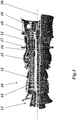
- FIG. 1 An exemplary gas turbine of the applicant with sequential combustion, which is known as GT26, is shown in Fig. 1 .
- Gas turbine 10 of Fig. 1 comprises a rotor 11 with a plurality of blades rotating about a machine axis 20 and being surrounded by a casing 12. Air is taken in at air inlet 13 and is compressed by compressor 14. The compressed air is used to burn a first fuel in a first (annular) combustor 15, thereby generating hot gas. The hot gas drives a first, high pressure (HP) turbine 16, is then reheated in a second (annular, sequential) combustor 17, drives a second, low pressure (LP) turbine 18 and exits gas turbine 10 through exhaust gas outlet 19.
- HP high pressure
- LP low pressure
- the operating conditions allow self ignition (spontaneous ignition) of the fuel air mixture without additional energy being supplied to the mixture.
- the residence time therein must not exceed the auto ignition delay time. This criterion ensures flame-free zones inside the burner. This criterion poses challenges in obtaining appropriate distribution of the fuel across the burner exit area. SEV-burners are currently designed for operation on natural gas and oil only. Therefore, the momentum flux of the fuel is adjusted relative to the momentum flux of the main flow so as to penetrate into the vortices.
- the subsequent mixing of the fuel and the oxidizer at the exit of the mixing zone is just sufficient to allow low NOx emissions (mixing quality) and avoid flashback (residence time), which may be caused by auto ignition of the fuel air mixture in the mixing zone.
- the cross flow injection concept used in the current SEV-fuel injection devices (SEV fuel lances) necessitates high-pressure carrier air supply, which reduces the overall efficiency of the power plant.
- Document EP 2 522 912 A1 relates to a combined flow straightener and mixer as well as a burner for a combustion chamber of a gas turbine comprising such a mixing device.
- a combined function of flow straightening and mixing at least two streamlined bodies are arranged in a structure comprising the side walls of the mixer.
- the leading edge area of each streamlined body has a profile, which is oriented parallel to a main flow direction prevailing at the leading edge position, and wherein, with reference to a central plane of the streamlined bodies the trailing edges are provided with at least two lobes in opposite transverse directions.
- the periodic deflections forming the lobes from two adjacent streamlined bodies are out of phase.
- the disclosure further relates to a burner for a combustion chamber of a gas turbine, comprising such a flow straightener and mixer as well as at least one nozzle having its outlet orifice at or in a trailing edge of the streamlined body. Further, it relates to the operation of such a burner.
- Document EP 2 725 301 A1 relates to a burner for a combustion chamber of a gas turbine with a mixing and injection device, wherein the mixing and injection device is comprising a limiting wall that defines a gas-flow channel and at least two streamlined bodies, each extending in a first transverse direction into the gas-flow channel.
- Each streamlined body has two lateral surfaces that are arranged essentially parallel to the main-flow direction, the lateral surfaces being joined to one another at their upstream side to form a leading edge of the body and joined at their downstream side to form a trailing edge of the body.
- Each streamlined body has a cross-section perpendicular to the first transverse direction that is shaped as a streamlined profile.
- At least one of said streamlined bodies is provided with a mixing structure and with at least one fuel nozzle located at its trailing edge for introducing at least one fuel essentially parallel to the main-flow direction into the flow channel, wherein at least two of the streamlined bodies have different lengths along the first transverse direction such that they may be used for a can combustor.
- Document EP 2 725 303 A2 discloses a reheat burner arrangement comprising a center body, an annular duct with a cross-section area, an intermediate fuel injection plane located along the center body and being actively connected to the cross section area of the annular duct, wherein the center body is located upstream of a combustion chamber, wherein the structure of the reheat burner arrangement is defined by various parameters and the structure of the reheat burner arrangement is defined by various dependencies.
- second combustor 17 of exemplary gas turbine 10 of Fig. 1 is of an annular design
- other secondary combustors are of a rectangular design.
- Document WO 2011/054766 A2 discloses (especially in Fig. 6) a burner of a rectangular design for a combustion chamber of a gas turbine, with an injection device for the introduction of at least one gaseous and/or liquid fuel into the burner, wherein the injection device has at least one body which is arranged in the burner with at least one nozzle for introducing the at least one fuel into the burner, the at least one body being configured as a streamlined body which has a streamlined cross-sectional profile and which extends with a longitudinal direction perpendicularly or at an inclination to a main flow direction prevailing in the burner, the at least one nozzle having its outlet orifice at or in a trailing edge of the streamlined body, and wherein, with reference to a central plane of the streamlined body the trailing edge is provided with at least two lobes in opposite transverse directions.
- Document EP 2 725 301 A1 discloses a lobe lance for a gas turbine combustor, comprising a plurality of streamlined lobe fingers with lateral surfaces essentially parallel to a direction of hot gas flow.
- the lateral surfaces join at their upstream side and downstream side forming a leading edge and a trailing edge, respectively.
- Nozzles for injecting a gaseous and/or liquid fuel mixed with air are distributed along the trailing edge and lobes running between nozzles are provided at the trailing edge.
- the lobes of each lobe finger can have one of two opposite orientations with respect to the flow direction, and the lobes of all lobe fingers follow a predetermined pattern of orientation across the lobe fingers.
- At least one pair of neighboring lobe fingers has the same lobe orientation resulting in a grouped lobe arrangement such that at least two of the vortices generated by the lobe shape downstream of the lobe fingers combine.
- N N R + N L with N R being the number of lobe fingers having a first lobe orientation, and N L being the number of lobe fingers having a second lobe orientation opposite to the first lobe orientation.
- the lobe lance according to the invention for a gas turbine combustor comprises a plurality of N (N ⁇ 4) lobe fingers, whereby each of said lobe fingers is configured as a streamlined body which has a streamlined cross-sectional profile, whereby said body has two lateral surfaces essentially parallel to a direction of hot gas flow, whereby said lateral surfaces are joined at their upstream side by a leading edge and joined at their downstream side forming a trailing edge, whereby a plurality of nozzles for injecting a gaseous and/or liquid fuel mixed with air is distributed along said trailing edge, and whereby lobes running between said nozzles are provided at said trailing edge for improving the mixing quality and reducing pressure loss in said combustor.
- the lobes of each lobe finger can have one of two opposite orientations with respect to said flow direction, and that the lobes of all lobe fingers follow a predetermined pattern of orientation across the lobe fingers, and at least one pair of neighboring lobe fingers (22a-d) has the same lobe orientation resulting in a grouped lobe arrangement (...LL...or...RR9) such that at least two of the vortices generated by the lobe shape downstream of said lobe fingers combine.
- N N R + N L with N R being the number of lobe fingers having a first lobe orientation, and N L being the number of lobe fingers having a second lobe orientation opposite to said first lobe orientation.
- N R and N L are both at least 1.
- N R and N L are equal or approximately equal.
- At least one pair of neighboring lobe fingers has the same lobe orientation resulting in a grouped lobe arrangement, which allows some of the vortices generated by the lobe shape downstream of said lobe fingers to combine into a single vortex, and thereby enhance mixing.
- a combined single vortex can have a larger cross section in a plane normal to the main flow direction than each of the vortices leaving the lobe fingers thereby enhancing a mixing across a burner.
- said predetermined pattern of orientation is one of the following patterns:
- N 8
- said predetermined pattern of orientation is one of the following patterns:
- N 4.
- said predetermined pattern of orientation is either RRLL or LLRR.
- said predetermined pattern of orientation is either RLLR or LRRL.
- said predetermined pattern of orientation is one of the following patterns:
- said lobe fingers are arranged between left and right side walls, and the two lobe fingers adjacent to said side walls have a predetermined lobe orientation according to one of the following schemes:
- each of said lobe fingers has an even number of nozzles, and that the two lobe fingers adjacent to said side walls have a predetermined lobe orientation according the scheme (left wall) R... L (right wall).
- each lobe finger has a lobe finger chord bisecting the lobe finger from the leading edge to the trailing edge and the lobe finger chords of two of said lobe fingers are closer to each other at the trailing edge than at the leading edge.
- Another embodiment comprises a gas turbine comprising a lobe lance as described above.
- a second burner of a gas turbine with sequential combustion can comprise a lobe lance as described above.
- the lobe lance can also be provided in a second burner of a gas turbine with sequential combustion without a high pressure turbine between first and second combustors.
- Such a gas turbine architecture is for example shown in WO2012136787A1 .
- grouped or alternating neighboring lobe fingers are the cause to have local combined vortices (grouped) or not (alternating); thus it defines the level of large scale mixing of fuel, cooling air and hot gas.
- the arrangement is defined based on the burner size and possible numbers of lobe fingers. With current rectangular sequential burner, a four finger arrangement is proper. However, the arrangements will not be limited to four finger arrangements.
- an arrangement of three lobe fingers behaves differently than an arrangement with four fingers or more.
- grouped lobes allow the vortices to combine with each other (two or more vortices can combine into a single vortex) and thereby create large scale structures, which enhance mixing and are thus beneficial for NOx, CO and overall temperature distribution factor (OTDF).
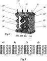
- Lobe lance 21 of Fig. 2 which is preferably to be used with a rectangular burner, comprises four separate fingers 22a-d extending in parallel between an upper plate 25 and a lower plate 26.
- Each finger 22 is configured as a streamlined body which has a streamlined cross-sectional profile (like an airfoil).
- the body has two lateral surfaces essentially parallel to an axial hot gas flow with flow direction 32, which passes through the lance between upper and lower plates 25, 26.
- the lateral surfaces are joined at their upstream side by a leading edge 23 and joined at their downstream side forming a trailing edge 24.
- a plurality of nozzles 27 for injecting a gaseous and/or liquid fuel mixed with air is distributed along the trailing edge 24.
- Each of said fingers 22 has an air plenum 30 for air supply, a gas plenum 31 for gaseous fuel supply, and a liquid fuel supply 29.
- Means for improving the mixing quality and reducing pressure loss in said secondary combustor are provided in the trailing edge region of said body in form of lobes 28 running between the nozzles 27 at the trailing edge 24.
- Lobes 28 of the various fingers 22 generate vortices in the downstream flow of the fuel/air mixture, whereby the vortex flow of the different fingers 22 interact with each other. This interaction, which is able to enhance the mixing effect, depends on the orientation of lobes 28 in each finger.
- the lobes 28 of the different fingers 22a-d can have two different orientations.
- the lobes 28 of the left two fingers 22a and 22b have the same orientation, which is opposite to the orientation of the lobes 28 of the right two fingers 22c and 22d.
- the lobe orientation of fingers 22a and 22b is said to be R (for right), while the lobe orientation of fingers 22c and 22d is said to be L (for left).
- N 4 in the case shown in Fig. 2 ).
- N R is the number of lobe fingers with lobe orientation R (N R ⁇ N), i.e. fingers having the trailing edge lobe pointing in right direction when looking in downstream direction.
- R and L there are two opposite types of directions or orientations (R and L).
- the case where the lobes of two neighboring fingers have the same trailing edge direction or orientation is referred to as a "grouped lobe arrangement” (...LL... or ...RR%), while the cases where the lobes of two neighboring fingers have the opposite trailing edge direction or orientation is referred to as an "alternating lobe arrangement" (... LR... or ...RL).
- the streamwise vortices generated by the lobe shape are in the same direction, which are observed to combine to bigger vortices, in case the shape of lobe and the distance between two lobe fingers is properly designed or adjusted.
- the first version R... L is preferred.
- two or more of the lobe fingers are arranged such that their trailing edges are closer together than their leading edges (e.g. in Fig. 2 ).
- two or more lobe fingers with the same orientation are arranged such that their trailing edges are closer together than their leading edges.
- Each lobe finger has a chord stretching from its leading edge to its trailing edge. This chord would normally be substantially parallel to the hot gas flow, and would normally bisect a cross-section of the lobe finger.
- the lobe lance could have all the lobe fingers in this configuration, particularly when four lobe fingers are provided.
- Fig. 2 The example shown in Fig. 2 is in a secondary combustor in a sequential combustion turbine. In some cases, such as single combustor turbines, this invention could be incorporated in a first stage combustor. In cases where three or more combustors are provided, the invention could be incorporated in the third or later stage.
Landscapes
- Engineering & Computer Science (AREA)
- Chemical & Material Sciences (AREA)
- Combustion & Propulsion (AREA)
- Mechanical Engineering (AREA)
- General Engineering & Computer Science (AREA)
- Nozzles For Spraying Of Liquid Fuel (AREA)
- Pre-Mixing And Non-Premixing Gas Burner (AREA)
- Gas Burners (AREA)
- Spray-Type Burners (AREA)
Claims (12)
- Nockenlanze (21) für eine Gasturbinenbrennkammer, die eine Mehrzahl N (N ≥ 4) Nockenfinger (22a-d) aufweist, wobei jeder Nockenfinger (22a-d) als stromlinienförmiger Körper ausgelegt ist, der ein stromlinienförmiges Querschnittsprofil aufweist, wobei der Körper zwei Seitenflächen aufweist, die im Wesentlichen parallel zu einer Richtung (32) eines Heißgasstroms sind, wobei die Seitenflächen an ihrer stromaufwärtigen Seite durch eine Vorderkante (23) verbunden sind und an ihrer stromabwärtigen Seite zusammengefügt sind und eine Hinterkante (24) bilden, wobei entlang der Hinterkante (24) mehrere Düsen (27) zur Einspritzung eines gasförmigen und/oder flüssigen, mit Luft gemischten Brennstoffs verteilt sind, und wobei an der Hinterkante (24) Nocken (28), die zwischen den Düsen (27) verlaufen, zur Verbesserung der Mischqualität und Verringerung des Druckverlusts in der Brennkammer bereitgestellt sind, wobei die Nocken (28) jedes Nockenfingers (22a-d) eine von zwei entgegengesetzten Richtungen (R, L) in Bezug auf die Strömungsrichtung (32) aufweisen können und die Nocken (28) aller Nockenfinger (22a-d) einem vorbestimmten Ausrichtungsmuster über die Nockenfinger (22a d) hinweg folgen, wobei mindestens ein Paar benachbarter Nockenfinger (22a-d) dieselbe Nockenausrichtung in einer gruppierten Nockenanordnung (...LL...oder...RR...) aufweist, so dass mindestens zwei der durch Nockenform erzeugten Wirbel sich stromabwärts der Nockenfinger (22a-d) vereinen und wobei N = NR + NL, wobei NR die Anzahl der Nockenfinger mit einer ersten Nockenausrichtung (R) ist und NL die Anzahl der Nockenfinger mit einer zweiten Nockenausrichtung (L) entgegengesetzt zu der ersten Nockenausrichtung ist, dadurch gekennzeichnet, dass sowohl NR als auch NL mindestens 1 sind.
- Nockenlanze nach Anspruch 1, dadurch gekennzeichnet, dass NR und NL ungefähr gleich oder gleich sind.
- Nockenlanze nach Anspruch 1, dadurch gekennzeichnet, dass das vorbestimmte Ausrichtungsmuster eines der folgenden Muster ist:• RR...RRLL...LL,• LL...LLRR...RR,• RR...RRLL...LLRR (...RRLL...LL),• LL...LLRR...RR (LL...LLRR...RR),• RRLL...LLRR (...RRLL),• LLRR...RRLL (...RRLL),wobei N/2 = NR = NL, wenn N eine gerade Zahl ist, oder wobei N/2 = NR +0,5 = NL - 0,5 oder N/2 = NR - 0,5 = NL + 0,5, wenn N eine ungerade Zahl ist.
- Nockenlanze nach Anspruch 3, dadurch gekennzeichnet, dass N = 8 und dass das vorbestimmte Ausrichtungsmuster eines der folgenden Muster ist:• RRRRLLLL,• LLLLRRRR,• RRLLRRLL,• LLRRLLRR,• RRLLLLRR,• LLRRRRLL.
- Nockenlanze nach Anspruch 1, dadurch gekennzeichnet, dass N = 4 ist.
- Nockenlanze nach Anspruch 5, dadurch gekennzeichnet, dass das vorbestimmte Ausrichtungsmuster entweder RRLL oder LLRR ist.
- Nockenlanze nach Anspruch 5, dadurch gekennzeichnet, dass das vorbestimmte Ausrichtungsmuster entweder RLLR oder LRRL ist.
- Nockenlanze nach Anspruch 5, dadurch gekennzeichnet, dass das vorbestimmte Ausrichtungsmuster eines der folgenden Muster ist:• RRRL, RLLL,• LLLR, LRRR,• RRRR, LLLL.
- Nockenlanze nach Anspruch 1, dadurch gekennzeichnet, dass die Nockenfinger (22a-d) zwischen der linken und rechten Seitenwand angeordnet sind und dass die zwei Nockenfinger, die zu den Seitenwänden benachbart sind, eine vorbestimmte Nockenausrichtung gemäß einem der folgenden Schemata aufweisen:• (linke Wand) R...L (rechte Wand),• (linke Wand) L...R (rechte Wand) .
- Nockenlanze nach Anspruch 9, dadurch gekennzeichnet, dass jeder Nockenfinger (22a-d) eine gerade Anzahl von Düsen (27) aufweist und dass die zwei Nockenfinger, die zu den Seitenwänden benachbart sind, eine vorbestimmte Nockenausrichtung gemäß dem Schema (linke Wand) R...L (rechte Wand) aufweisen.
- Nockenlanze nach Anspruch 1, dadurch gekennzeichnet, dass jeder Nockenfinger (22a-d) eine Nockenfingersehne aufweist, die den Nockenfinger von der Vorderkante zur Hinterkante halbiert, und die Nockenfingersehnen von zwei der Nockenfinger (22a-d) an der Hinterkante (23) näher beieinander liegen als an der Vorderkante (24).
- Gasturbine, die die Nockenlanze (21) nach einem der vorhergehenden Ansprüche umfasst.
Priority Applications (5)
| Application Number | Priority Date | Filing Date | Title |
|---|---|---|---|
| EP14195483.4A EP3023696B1 (de) | 2014-11-20 | 2014-11-28 | Nockenlanze für eine Gasturbinenbrennkammer |
| JP2015226314A JP2016105035A (ja) | 2014-11-20 | 2015-11-19 | ガスタービン燃焼器用のローブランス |
| KR1020150163426A KR20160060594A (ko) | 2014-11-20 | 2015-11-20 | 가스 터빈 연소기용 로브 랜스 |
| US14/947,386 US10443852B2 (en) | 2014-11-20 | 2015-11-20 | Lobe lance for a gas turbine combustor |
| CN201510804715.7A CN105627368B (zh) | 2014-11-20 | 2015-11-20 | 用于燃气涡轮燃烧器的波瓣喷管 |
Applications Claiming Priority (2)
| Application Number | Priority Date | Filing Date | Title |
|---|---|---|---|
| EP14194098 | 2014-11-20 | ||
| EP14195483.4A EP3023696B1 (de) | 2014-11-20 | 2014-11-28 | Nockenlanze für eine Gasturbinenbrennkammer |
Publications (2)
| Publication Number | Publication Date |
|---|---|
| EP3023696A1 EP3023696A1 (de) | 2016-05-25 |
| EP3023696B1 true EP3023696B1 (de) | 2019-08-28 |
Family
ID=51987008
Family Applications (2)
| Application Number | Title | Priority Date | Filing Date |
|---|---|---|---|
| EP14195483.4A Active EP3023696B1 (de) | 2014-11-20 | 2014-11-28 | Nockenlanze für eine Gasturbinenbrennkammer |
| EP15193075.7A Active EP3023697B1 (de) | 2014-11-20 | 2015-11-04 | Brennstofflanzenkühlung für eine gasturbine mit sequenzieller verbrennung |
Family Applications After (1)
| Application Number | Title | Priority Date | Filing Date |
|---|---|---|---|
| EP15193075.7A Active EP3023697B1 (de) | 2014-11-20 | 2015-11-04 | Brennstofflanzenkühlung für eine gasturbine mit sequenzieller verbrennung |
Country Status (5)
| Country | Link |
|---|---|
| US (2) | US10920985B2 (de) |
| EP (2) | EP3023696B1 (de) |
| JP (2) | JP2016105035A (de) |
| KR (2) | KR20160060565A (de) |
| CN (2) | CN105627367B (de) |
Families Citing this family (30)
| Publication number | Priority date | Publication date | Assignee | Title |
|---|---|---|---|---|
| EP2837883B1 (de) * | 2013-08-16 | 2018-04-04 | Ansaldo Energia Switzerland AG | Vorgemischter Rohrbrenner mit wellenförmigen Vormischflügeln für die zweite Stufe einer sequentiellen Gasturbine |
| EP3056819B1 (de) | 2015-02-11 | 2020-04-01 | Ansaldo Energia Switzerland AG | Kraftstoffeinspritzungsvorrichtung für eine Gasturbine |
| US10151325B2 (en) * | 2015-04-08 | 2018-12-11 | General Electric Company | Gas turbine diffuser strut including a trailing edge flap and methods of assembling the same |
| US9989257B2 (en) | 2015-06-24 | 2018-06-05 | Delavan Inc | Cooling in staged fuel systems |
| EP3115693B1 (de) * | 2015-07-10 | 2021-09-01 | Ansaldo Energia Switzerland AG | Sequentielle brennkammer und verfahren zum betrieb davon |
| RU2717472C2 (ru) * | 2016-08-16 | 2020-03-23 | Ансальдо Энергия Свитзерленд Аг | Инжекторное устройство и способ изготовления инжекторного устройства |
| US11067277B2 (en) | 2016-10-07 | 2021-07-20 | General Electric Company | Component assembly for a gas turbine engine |
| EP3306197B1 (de) | 2016-10-08 | 2020-01-29 | Ansaldo Energia Switzerland AG | Zweikraftstoffinjektor für einen brenner der zweiten stufe einer sequentiellen gasturbine |
| US10436062B2 (en) * | 2016-11-17 | 2019-10-08 | United Technologies Corporation | Article having ceramic wall with flow turbulators |
| EP3324120B1 (de) * | 2016-11-18 | 2019-09-18 | Ansaldo Energia Switzerland AG | Mit additiver fertigung erzeugte gasturbinen-brennstoffinjektoranordnung |
| EP3330614B1 (de) | 2016-11-30 | 2019-10-02 | Ansaldo Energia Switzerland AG | Wirbelerzeugungsvorrichtung |
| EP3330613B1 (de) | 2016-11-30 | 2020-10-21 | Ansaldo Energia Switzerland AG | Wirbelerzeugungsvorrichtung |
| EP3354984B1 (de) * | 2017-01-31 | 2020-09-09 | Ansaldo Energia Switzerland AG | Gelappter injektor für eine gasturbinenbrennkammer |
| WO2018208695A1 (en) * | 2017-05-08 | 2018-11-15 | Clearsign Combustion Corporation | Combustion system including a mixing tube and a perforated flame holder |
| RU2747655C2 (ru) * | 2017-11-17 | 2021-05-11 | Ансальдо Энергия Свитзерленд Аг | Горелка промежуточного подогрева для газовой турбины и газовая турбина, содержащая такую горелку промежуточного подогрева |
| US11242806B2 (en) * | 2017-11-20 | 2022-02-08 | Power Systems Mfg., Llc | Method of controlling fuel injection in a reheat combustor for a combustor unit of a gas turbine |
| GB201907834D0 (en) * | 2019-06-03 | 2019-07-17 | Rolls Royce Plc | A fuel sparay nozzle arrangement |
| EP3748231B1 (de) * | 2019-06-05 | 2023-08-30 | Siemens Energy Global GmbH & Co. KG | Brenner und brennerspitze |
| US11187155B2 (en) | 2019-07-22 | 2021-11-30 | Delavan Inc. | Sectional fuel manifolds |
| KR102403823B1 (ko) * | 2019-12-13 | 2022-05-30 | 두산에너빌리티 주식회사 | 스트립이 형성된 배기 디퓨져의 스트롯 구조 및 가스터빈 |
| CN111878253A (zh) * | 2020-07-31 | 2020-11-03 | 中国人民解放军国防科技大学 | 波瓣式火箭喷嘴以及火箭基组合循环推进系统 |
| US11994293B2 (en) * | 2020-08-31 | 2024-05-28 | General Electric Company | Impingement cooling apparatus support structure and method of manufacture |
| US11408610B1 (en) | 2021-02-03 | 2022-08-09 | General Electric Company | Systems and methods for spraying fuel in an augmented gas turbine engine |
| US12181151B2 (en) | 2021-07-29 | 2024-12-31 | General Electric Company | Mixer vanes having a waveform profile |
| CN113898973B (zh) * | 2021-09-15 | 2022-10-21 | 南京航空航天大学 | 一种油气复合冷却式火焰稳定器及燃烧室 |
| US11898755B2 (en) | 2022-06-08 | 2024-02-13 | General Electric Company | Combustor with a variable volume primary zone combustion chamber |
| US11835236B1 (en) | 2022-07-05 | 2023-12-05 | General Electric Company | Combustor with reverse dilution air introduction |
| CN118371664B (zh) * | 2024-04-15 | 2024-12-06 | 江苏万恒新材料科技有限公司 | 一种压缩机外壳成型模具及其工艺 |
| US12474055B2 (en) * | 2024-05-09 | 2025-11-18 | Ge Infrastructure Technology Llc | Axial fuel stage injector with axially elongated mixing chambers with axially wavy inlets |
| CN119778758B (zh) * | 2024-12-23 | 2025-10-17 | 北京航空航天大学 | 四爪防振环装置、燃烧室及燃气涡轮 |
Family Cites Families (39)
| Publication number | Priority date | Publication date | Assignee | Title |
|---|---|---|---|---|
| US3578264A (en) * | 1968-07-09 | 1971-05-11 | Battelle Development Corp | Boundary layer control of flow separation and heat exchange |
| US4407632A (en) * | 1981-06-26 | 1983-10-04 | United Technologies Corporation | Airfoil pedestaled trailing edge region cooling configuration |
| FR2696502B1 (fr) * | 1992-10-07 | 1994-11-04 | Snecma | Dispositif de post-combustion pour turbo réacteur double flux. |
| CH674561A5 (de) | 1987-12-21 | 1990-06-15 | Bbc Brown Boveri & Cie | |
| EP0577862B1 (de) | 1992-07-03 | 1997-03-12 | Abb Research Ltd. | Nachbrenner |
| JPH07279612A (ja) * | 1994-04-14 | 1995-10-27 | Mitsubishi Heavy Ind Ltd | 重質油焚き用ガスタービン冷却翼 |
| DE4426351B4 (de) | 1994-07-25 | 2006-04-06 | Alstom | Brennkammer für eine Gasturbine |
| US6325593B1 (en) * | 2000-02-18 | 2001-12-04 | General Electric Company | Ceramic turbine airfoils with cooled trailing edge blocks |
| DE10008006C2 (de) | 2000-02-22 | 2003-10-16 | Graffinity Pharm Design Gmbh | SPR-Sensor und SPR-Sensoranordnung |
| DE10128063A1 (de) | 2001-06-09 | 2003-01-23 | Alstom Switzerland Ltd | Brennersystem |
| US6758651B2 (en) * | 2002-10-16 | 2004-07-06 | Mitsubishi Heavy Industries, Ltd. | Gas turbine |
| US6916150B2 (en) * | 2003-11-26 | 2005-07-12 | Siemens Westinghouse Power Corporation | Cooling system for a tip of a turbine blade |
| US7104756B2 (en) * | 2004-08-11 | 2006-09-12 | United Technologies Corporation | Temperature tolerant vane assembly |
| US7128533B2 (en) | 2004-09-10 | 2006-10-31 | Siemens Power Generation, Inc. | Vortex cooling system for a turbine blade |
| US20070122266A1 (en) * | 2005-10-14 | 2007-05-31 | General Electric Company | Assembly for controlling thermal stresses in ceramic matrix composite articles |
| US7621718B1 (en) | 2007-03-28 | 2009-11-24 | Florida Turbine Technologies, Inc. | Turbine vane with leading edge fillet region impingement cooling |
| JP2009162119A (ja) | 2008-01-08 | 2009-07-23 | Ihi Corp | タービン翼の冷却構造 |
| EP2154428A1 (de) * | 2008-08-11 | 2010-02-17 | Siemens Aktiengesellschaft | Brennstoffeinsatz |
| GB2466478A (en) * | 2008-12-02 | 2010-06-30 | Aerovortex Mills Ltd | Suction generation device |
| EP2496882B1 (de) * | 2009-11-07 | 2018-03-28 | Ansaldo Energia Switzerland AG | Injektionssystem mit brennstofflanzen für einen nachbrenner |
| WO2011054760A1 (en) | 2009-11-07 | 2011-05-12 | Alstom Technology Ltd | A cooling scheme for an increased gas turbine efficiency |
| WO2011054739A2 (en) * | 2009-11-07 | 2011-05-12 | Alstom Technology Ltd | Reheat burner injection system |
| EP2496883B1 (de) * | 2009-11-07 | 2016-08-10 | Alstom Technology Ltd | Vormischrbrenner für einen gasturbinenbrenner |
| EP2496884B1 (de) | 2009-11-07 | 2016-12-28 | General Electric Technology GmbH | Injektionssystem für einen nachbrenner |
| EP2362148A1 (de) | 2010-02-23 | 2011-08-31 | Siemens Aktiengesellschaft | Brennstoffinjektor und Drallvorrichtung mit lappenartigem Mischer |
| US9511447B2 (en) * | 2013-12-12 | 2016-12-06 | General Electric Company | Process for making a turbulator by additive manufacturing |
| GB201105790D0 (en) * | 2011-04-06 | 2011-05-18 | Rolls Royce Plc | A cooled double walled article |
| CH704829A2 (de) | 2011-04-08 | 2012-11-15 | Alstom Technology Ltd | Gasturbogruppe und zugehöriges Betriebsverfahren. |
| RU2550370C2 (ru) * | 2011-05-11 | 2015-05-10 | Альстом Текнолоджи Лтд | Центробежная форсунка с выступающими частями |
| EP2522912B1 (de) | 2011-05-11 | 2019-03-27 | Ansaldo Energia Switzerland AG | Strömungsgleichrichter und Mischer |
| US20120324903A1 (en) * | 2011-06-27 | 2012-12-27 | Icr Turbine Engine Corporation | High efficiency compact gas turbine engine |
| US8745988B2 (en) * | 2011-09-06 | 2014-06-10 | Pratt & Whitney Canada Corp. | Pin fin arrangement for heat shield of gas turbine engine |
| US9243803B2 (en) | 2011-10-06 | 2016-01-26 | General Electric Company | System for cooling a multi-tube fuel nozzle |
| CA2830031C (en) * | 2012-10-23 | 2016-03-15 | Alstom Technology Ltd. | Burner for a can combustor |
| EP2725302A1 (de) * | 2012-10-25 | 2014-04-30 | Alstom Technology Ltd | Nachbrenneranordnung |
| EP2971966B1 (de) * | 2013-03-15 | 2017-04-19 | Rolls-Royce Corporation | Innenverkleidung für eine gasturbinenbrennkammer |
| US9458767B2 (en) * | 2013-03-18 | 2016-10-04 | General Electric Company | Fuel injection insert for a turbine nozzle segment |
| EP2796789B1 (de) * | 2013-04-26 | 2017-03-01 | General Electric Technology GmbH | Rohrbrennkammer für eine Rohr-Ring Anordnung in einer Gasturbine |
| US8864438B1 (en) * | 2013-12-05 | 2014-10-21 | Siemens Energy, Inc. | Flow control insert in cooling passage for turbine vane |
-
2014
- 2014-11-28 EP EP14195483.4A patent/EP3023696B1/de active Active
-
2015
- 2015-11-04 EP EP15193075.7A patent/EP3023697B1/de active Active
- 2015-11-18 KR KR1020150161568A patent/KR20160060565A/ko not_active Withdrawn
- 2015-11-19 JP JP2015226314A patent/JP2016105035A/ja active Pending
- 2015-11-20 KR KR1020150163426A patent/KR20160060594A/ko not_active Withdrawn
- 2015-11-20 US US14/947,701 patent/US10920985B2/en not_active Expired - Fee Related
- 2015-11-20 CN CN201510804652.5A patent/CN105627367B/zh active Active
- 2015-11-20 US US14/947,386 patent/US10443852B2/en active Active
- 2015-11-20 JP JP2015227247A patent/JP2016099108A/ja active Pending
- 2015-11-20 CN CN201510804715.7A patent/CN105627368B/zh active Active
Non-Patent Citations (1)
| Title |
|---|
| None * |
Also Published As
| Publication number | Publication date |
|---|---|
| US20160146466A1 (en) | 2016-05-26 |
| US10920985B2 (en) | 2021-02-16 |
| CN105627367B (zh) | 2019-11-05 |
| EP3023697B1 (de) | 2017-10-04 |
| EP3023697A1 (de) | 2016-05-25 |
| US10443852B2 (en) | 2019-10-15 |
| US20160146468A1 (en) | 2016-05-26 |
| JP2016099108A (ja) | 2016-05-30 |
| CN105627368A (zh) | 2016-06-01 |
| EP3023696A1 (de) | 2016-05-25 |
| JP2016105035A (ja) | 2016-06-09 |
| CN105627367A (zh) | 2016-06-01 |
| KR20160060565A (ko) | 2016-05-30 |
| CN105627368B (zh) | 2020-06-05 |
| KR20160060594A (ko) | 2016-05-30 |
Similar Documents
| Publication | Publication Date | Title |
|---|---|---|
| EP3023696B1 (de) | Nockenlanze für eine Gasturbinenbrennkammer | |
| US8402768B2 (en) | Reheat burner injection system | |
| US10544939B2 (en) | Burner for a can combustor | |
| US8677756B2 (en) | Reheat burner injection system | |
| EP2522911B1 (de) | Brenner mit lobe drallerzeuger | |
| US8490398B2 (en) | Premixed burner for a gas turbine combustor | |
| EP2522912B1 (de) | Strömungsgleichrichter und Mischer | |
| KR101663495B1 (ko) | 재열 버너 장치 | |
| US10215416B2 (en) | Burner of a gas turbine with a lobed shape vortex generator | |
| EP2933559A1 (de) | Kraftstoffmischanordnung und Brennkammer mit einer solchen Mischanordnung | |
| EP3354984B1 (de) | Gelappter injektor für eine gasturbinenbrennkammer |
Legal Events
| Date | Code | Title | Description |
|---|---|---|---|
| AK | Designated contracting states |
Kind code of ref document: A1 Designated state(s): AL AT BE BG CH CY CZ DE DK EE ES FI FR GB GR HR HU IE IS IT LI LT LU LV MC MK MT NL NO PL PT RO RS SE SI SK SM TR |
|
| AX | Request for extension of the european patent |
Extension state: BA ME |
|
| PUAI | Public reference made under article 153(3) epc to a published international application that has entered the european phase |
Free format text: ORIGINAL CODE: 0009012 |
|
| RAP1 | Party data changed (applicant data changed or rights of an application transferred) |
Owner name: GENERAL ELECTRIC TECHNOLOGY GMBH |
|
| STAA | Information on the status of an ep patent application or granted ep patent |
Free format text: STATUS: REQUEST FOR EXAMINATION WAS MADE |
|
| 17P | Request for examination filed |
Effective date: 20161124 |
|
| RBV | Designated contracting states (corrected) |
Designated state(s): AL AT BE BG CH CY CZ DE DK EE ES FI FR GB GR HR HU IE IS IT LI LT LU LV MC MK MT NL NO PL PT RO RS SE SI SK SM TR |
|
| RAP1 | Party data changed (applicant data changed or rights of an application transferred) |
Owner name: ANSALDO ENERGIA SWITZERLAND AG |
|
| GRAP | Despatch of communication of intention to grant a patent |
Free format text: ORIGINAL CODE: EPIDOSNIGR1 |
|
| STAA | Information on the status of an ep patent application or granted ep patent |
Free format text: STATUS: GRANT OF PATENT IS INTENDED |
|
| INTG | Intention to grant announced |
Effective date: 20190325 |
|
| GRAS | Grant fee paid |
Free format text: ORIGINAL CODE: EPIDOSNIGR3 |
|
| GRAA | (expected) grant |
Free format text: ORIGINAL CODE: 0009210 |
|
| STAA | Information on the status of an ep patent application or granted ep patent |
Free format text: STATUS: THE PATENT HAS BEEN GRANTED |
|
| AK | Designated contracting states |
Kind code of ref document: B1 Designated state(s): AL AT BE BG CH CY CZ DE DK EE ES FI FR GB GR HR HU IE IS IT LI LT LU LV MC MK MT NL NO PL PT RO RS SE SI SK SM TR |
|
| REG | Reference to a national code |
Ref country code: GB Ref legal event code: FG4D |
|
| REG | Reference to a national code |
Ref country code: CH Ref legal event code: EP |
|
| REG | Reference to a national code |
Ref country code: AT Ref legal event code: REF Ref document number: 1172873 Country of ref document: AT Kind code of ref document: T Effective date: 20190915 |
|
| REG | Reference to a national code |
Ref country code: IE Ref legal event code: FG4D |
|
| REG | Reference to a national code |
Ref country code: DE Ref legal event code: R096 Ref document number: 602014052441 Country of ref document: DE |
|
| REG | Reference to a national code |
Ref country code: NL Ref legal event code: MP Effective date: 20190828 |
|
| REG | Reference to a national code |
Ref country code: LT Ref legal event code: MG4D |
|
| PG25 | Lapsed in a contracting state [announced via postgrant information from national office to epo] |
Ref country code: FI Free format text: LAPSE BECAUSE OF FAILURE TO SUBMIT A TRANSLATION OF THE DESCRIPTION OR TO PAY THE FEE WITHIN THE PRESCRIBED TIME-LIMIT Effective date: 20190828 Ref country code: LT Free format text: LAPSE BECAUSE OF FAILURE TO SUBMIT A TRANSLATION OF THE DESCRIPTION OR TO PAY THE FEE WITHIN THE PRESCRIBED TIME-LIMIT Effective date: 20190828 Ref country code: PT Free format text: LAPSE BECAUSE OF FAILURE TO SUBMIT A TRANSLATION OF THE DESCRIPTION OR TO PAY THE FEE WITHIN THE PRESCRIBED TIME-LIMIT Effective date: 20191230 Ref country code: HR Free format text: LAPSE BECAUSE OF FAILURE TO SUBMIT A TRANSLATION OF THE DESCRIPTION OR TO PAY THE FEE WITHIN THE PRESCRIBED TIME-LIMIT Effective date: 20190828 Ref country code: SE Free format text: LAPSE BECAUSE OF FAILURE TO SUBMIT A TRANSLATION OF THE DESCRIPTION OR TO PAY THE FEE WITHIN THE PRESCRIBED TIME-LIMIT Effective date: 20190828 Ref country code: NO Free format text: LAPSE BECAUSE OF FAILURE TO SUBMIT A TRANSLATION OF THE DESCRIPTION OR TO PAY THE FEE WITHIN THE PRESCRIBED TIME-LIMIT Effective date: 20191128 Ref country code: NL Free format text: LAPSE BECAUSE OF FAILURE TO SUBMIT A TRANSLATION OF THE DESCRIPTION OR TO PAY THE FEE WITHIN THE PRESCRIBED TIME-LIMIT Effective date: 20190828 Ref country code: BG Free format text: LAPSE BECAUSE OF FAILURE TO SUBMIT A TRANSLATION OF THE DESCRIPTION OR TO PAY THE FEE WITHIN THE PRESCRIBED TIME-LIMIT Effective date: 20191128 |
|
| PG25 | Lapsed in a contracting state [announced via postgrant information from national office to epo] |
Ref country code: LV Free format text: LAPSE BECAUSE OF FAILURE TO SUBMIT A TRANSLATION OF THE DESCRIPTION OR TO PAY THE FEE WITHIN THE PRESCRIBED TIME-LIMIT Effective date: 20190828 Ref country code: ES Free format text: LAPSE BECAUSE OF FAILURE TO SUBMIT A TRANSLATION OF THE DESCRIPTION OR TO PAY THE FEE WITHIN THE PRESCRIBED TIME-LIMIT Effective date: 20190828 Ref country code: AL Free format text: LAPSE BECAUSE OF FAILURE TO SUBMIT A TRANSLATION OF THE DESCRIPTION OR TO PAY THE FEE WITHIN THE PRESCRIBED TIME-LIMIT Effective date: 20190828 Ref country code: GR Free format text: LAPSE BECAUSE OF FAILURE TO SUBMIT A TRANSLATION OF THE DESCRIPTION OR TO PAY THE FEE WITHIN THE PRESCRIBED TIME-LIMIT Effective date: 20191129 Ref country code: RS Free format text: LAPSE BECAUSE OF FAILURE TO SUBMIT A TRANSLATION OF THE DESCRIPTION OR TO PAY THE FEE WITHIN THE PRESCRIBED TIME-LIMIT Effective date: 20190828 Ref country code: IS Free format text: LAPSE BECAUSE OF FAILURE TO SUBMIT A TRANSLATION OF THE DESCRIPTION OR TO PAY THE FEE WITHIN THE PRESCRIBED TIME-LIMIT Effective date: 20191228 |
|
| REG | Reference to a national code |
Ref country code: AT Ref legal event code: MK05 Ref document number: 1172873 Country of ref document: AT Kind code of ref document: T Effective date: 20190828 |
|
| PG25 | Lapsed in a contracting state [announced via postgrant information from national office to epo] |
Ref country code: TR Free format text: LAPSE BECAUSE OF FAILURE TO SUBMIT A TRANSLATION OF THE DESCRIPTION OR TO PAY THE FEE WITHIN THE PRESCRIBED TIME-LIMIT Effective date: 20190828 |
|
| PG25 | Lapsed in a contracting state [announced via postgrant information from national office to epo] |
Ref country code: EE Free format text: LAPSE BECAUSE OF FAILURE TO SUBMIT A TRANSLATION OF THE DESCRIPTION OR TO PAY THE FEE WITHIN THE PRESCRIBED TIME-LIMIT Effective date: 20190828 Ref country code: PL Free format text: LAPSE BECAUSE OF FAILURE TO SUBMIT A TRANSLATION OF THE DESCRIPTION OR TO PAY THE FEE WITHIN THE PRESCRIBED TIME-LIMIT Effective date: 20190828 Ref country code: AT Free format text: LAPSE BECAUSE OF FAILURE TO SUBMIT A TRANSLATION OF THE DESCRIPTION OR TO PAY THE FEE WITHIN THE PRESCRIBED TIME-LIMIT Effective date: 20190828 Ref country code: RO Free format text: LAPSE BECAUSE OF FAILURE TO SUBMIT A TRANSLATION OF THE DESCRIPTION OR TO PAY THE FEE WITHIN THE PRESCRIBED TIME-LIMIT Effective date: 20190828 Ref country code: IT Free format text: LAPSE BECAUSE OF FAILURE TO SUBMIT A TRANSLATION OF THE DESCRIPTION OR TO PAY THE FEE WITHIN THE PRESCRIBED TIME-LIMIT Effective date: 20190828 Ref country code: DK Free format text: LAPSE BECAUSE OF FAILURE TO SUBMIT A TRANSLATION OF THE DESCRIPTION OR TO PAY THE FEE WITHIN THE PRESCRIBED TIME-LIMIT Effective date: 20190828 |
|
| PG25 | Lapsed in a contracting state [announced via postgrant information from national office to epo] |
Ref country code: SK Free format text: LAPSE BECAUSE OF FAILURE TO SUBMIT A TRANSLATION OF THE DESCRIPTION OR TO PAY THE FEE WITHIN THE PRESCRIBED TIME-LIMIT Effective date: 20190828 Ref country code: IS Free format text: LAPSE BECAUSE OF FAILURE TO SUBMIT A TRANSLATION OF THE DESCRIPTION OR TO PAY THE FEE WITHIN THE PRESCRIBED TIME-LIMIT Effective date: 20200224 Ref country code: SM Free format text: LAPSE BECAUSE OF FAILURE TO SUBMIT A TRANSLATION OF THE DESCRIPTION OR TO PAY THE FEE WITHIN THE PRESCRIBED TIME-LIMIT Effective date: 20190828 Ref country code: CZ Free format text: LAPSE BECAUSE OF FAILURE TO SUBMIT A TRANSLATION OF THE DESCRIPTION OR TO PAY THE FEE WITHIN THE PRESCRIBED TIME-LIMIT Effective date: 20190828 |
|
| REG | Reference to a national code |
Ref country code: DE Ref legal event code: R097 Ref document number: 602014052441 Country of ref document: DE |
|
| REG | Reference to a national code |
Ref country code: CH Ref legal event code: PL |
|
| PLBE | No opposition filed within time limit |
Free format text: ORIGINAL CODE: 0009261 |
|
| STAA | Information on the status of an ep patent application or granted ep patent |
Free format text: STATUS: NO OPPOSITION FILED WITHIN TIME LIMIT |
|
| PG2D | Information on lapse in contracting state deleted |
Ref country code: IS |
|
| PG25 | Lapsed in a contracting state [announced via postgrant information from national office to epo] |
Ref country code: CH Free format text: LAPSE BECAUSE OF NON-PAYMENT OF DUE FEES Effective date: 20191130 Ref country code: MC Free format text: LAPSE BECAUSE OF FAILURE TO SUBMIT A TRANSLATION OF THE DESCRIPTION OR TO PAY THE FEE WITHIN THE PRESCRIBED TIME-LIMIT Effective date: 20190828 Ref country code: LI Free format text: LAPSE BECAUSE OF NON-PAYMENT OF DUE FEES Effective date: 20191130 Ref country code: LU Free format text: LAPSE BECAUSE OF NON-PAYMENT OF DUE FEES Effective date: 20191128 |
|
| 26N | No opposition filed |
Effective date: 20200603 |
|
| REG | Reference to a national code |
Ref country code: BE Ref legal event code: MM Effective date: 20191130 |
|
| PG25 | Lapsed in a contracting state [announced via postgrant information from national office to epo] |
Ref country code: SI Free format text: LAPSE BECAUSE OF FAILURE TO SUBMIT A TRANSLATION OF THE DESCRIPTION OR TO PAY THE FEE WITHIN THE PRESCRIBED TIME-LIMIT Effective date: 20190828 |
|
| GBPC | Gb: european patent ceased through non-payment of renewal fee |
Effective date: 20191128 |
|
| PG25 | Lapsed in a contracting state [announced via postgrant information from national office to epo] |
Ref country code: GB Free format text: LAPSE BECAUSE OF NON-PAYMENT OF DUE FEES Effective date: 20191128 Ref country code: IE Free format text: LAPSE BECAUSE OF NON-PAYMENT OF DUE FEES Effective date: 20191128 Ref country code: FR Free format text: LAPSE BECAUSE OF NON-PAYMENT OF DUE FEES Effective date: 20191130 |
|
| PG25 | Lapsed in a contracting state [announced via postgrant information from national office to epo] |
Ref country code: BE Free format text: LAPSE BECAUSE OF NON-PAYMENT OF DUE FEES Effective date: 20191130 |
|
| PG25 | Lapsed in a contracting state [announced via postgrant information from national office to epo] |
Ref country code: CY Free format text: LAPSE BECAUSE OF FAILURE TO SUBMIT A TRANSLATION OF THE DESCRIPTION OR TO PAY THE FEE WITHIN THE PRESCRIBED TIME-LIMIT Effective date: 20190828 |
|
| PG25 | Lapsed in a contracting state [announced via postgrant information from national office to epo] |
Ref country code: HU Free format text: LAPSE BECAUSE OF FAILURE TO SUBMIT A TRANSLATION OF THE DESCRIPTION OR TO PAY THE FEE WITHIN THE PRESCRIBED TIME-LIMIT; INVALID AB INITIO Effective date: 20141128 Ref country code: MT Free format text: LAPSE BECAUSE OF FAILURE TO SUBMIT A TRANSLATION OF THE DESCRIPTION OR TO PAY THE FEE WITHIN THE PRESCRIBED TIME-LIMIT Effective date: 20190828 |
|
| PG25 | Lapsed in a contracting state [announced via postgrant information from national office to epo] |
Ref country code: MK Free format text: LAPSE BECAUSE OF FAILURE TO SUBMIT A TRANSLATION OF THE DESCRIPTION OR TO PAY THE FEE WITHIN THE PRESCRIBED TIME-LIMIT Effective date: 20190828 |
|
| P01 | Opt-out of the competence of the unified patent court (upc) registered |
Effective date: 20240430 |
|
| PGFP | Annual fee paid to national office [announced via postgrant information from national office to epo] |
Ref country code: DE Payment date: 20241119 Year of fee payment: 11 |