EP2837883B1 - Vorgemischter Rohrbrenner mit wellenförmigen Vormischflügeln für die zweite Stufe einer sequentiellen Gasturbine - Google Patents
Vorgemischter Rohrbrenner mit wellenförmigen Vormischflügeln für die zweite Stufe einer sequentiellen Gasturbine Download PDFInfo
- Publication number
- EP2837883B1 EP2837883B1 EP13180642.4A EP13180642A EP2837883B1 EP 2837883 B1 EP2837883 B1 EP 2837883B1 EP 13180642 A EP13180642 A EP 13180642A EP 2837883 B1 EP2837883 B1 EP 2837883B1
- Authority
- EP
- European Patent Office
- Prior art keywords
- burner
- combustion chamber
- lobes
- center body
- fuel
- Prior art date
- Legal status (The legal status is an assumption and is not a legal conclusion. Google has not performed a legal analysis and makes no representation as to the accuracy of the status listed.)
- Active
Links
- 238000002156 mixing Methods 0.000 title claims description 36
- 238000001816 cooling Methods 0.000 claims description 90
- 238000002485 combustion reaction Methods 0.000 claims description 83
- 239000000446 fuel Substances 0.000 claims description 56
- 239000007789 gas Substances 0.000 claims description 37
- 238000002347 injection Methods 0.000 claims description 30
- 239000007924 injection Substances 0.000 claims description 30
- 238000011144 upstream manufacturing Methods 0.000 claims description 16
- 230000007704 transition Effects 0.000 claims description 6
- 239000007788 liquid Substances 0.000 claims description 5
- 230000009467 reduction Effects 0.000 claims description 3
- 239000012159 carrier gas Substances 0.000 claims 1
- 239000002826 coolant Substances 0.000 claims 1
- 238000000034 method Methods 0.000 description 4
- 239000000567 combustion gas Substances 0.000 description 3
- 238000013016 damping Methods 0.000 description 3
- 230000015556 catabolic process Effects 0.000 description 2
- 230000003750 conditioning effect Effects 0.000 description 2
- 230000000694 effects Effects 0.000 description 2
- 230000010355 oscillation Effects 0.000 description 2
- 238000005192 partition Methods 0.000 description 2
- 230000009257 reactivity Effects 0.000 description 2
- 238000000926 separation method Methods 0.000 description 2
- 239000003381 stabilizer Substances 0.000 description 2
- 230000001143 conditioned effect Effects 0.000 description 1
- 230000002596 correlated effect Effects 0.000 description 1
- 230000007613 environmental effect Effects 0.000 description 1
- 238000004401 flow injection analysis Methods 0.000 description 1
- 230000017525 heat dissipation Effects 0.000 description 1
- 239000007800 oxidant agent Substances 0.000 description 1
- 230000001590 oxidative effect Effects 0.000 description 1
- 230000000737 periodic effect Effects 0.000 description 1
- 230000008569 process Effects 0.000 description 1
- 230000001737 promoting effect Effects 0.000 description 1
- 238000007789 sealing Methods 0.000 description 1
- 239000007787 solid Substances 0.000 description 1
- 230000007480 spreading Effects 0.000 description 1
- 230000006641 stabilisation Effects 0.000 description 1
- 238000011105 stabilization Methods 0.000 description 1
- 238000012876 topography Methods 0.000 description 1
Images


Classifications
-
- F—MECHANICAL ENGINEERING; LIGHTING; HEATING; WEAPONS; BLASTING
- F23—COMBUSTION APPARATUS; COMBUSTION PROCESSES
- F23R—GENERATING COMBUSTION PRODUCTS OF HIGH PRESSURE OR HIGH VELOCITY, e.g. GAS-TURBINE COMBUSTION CHAMBERS
- F23R3/00—Continuous combustion chambers using liquid or gaseous fuel
- F23R3/02—Continuous combustion chambers using liquid or gaseous fuel characterised by the air-flow or gas-flow configuration
- F23R3/16—Continuous combustion chambers using liquid or gaseous fuel characterised by the air-flow or gas-flow configuration with devices inside the flame tube or the combustion chamber to influence the air or gas flow
- F23R3/18—Flame stabilising means, e.g. flame holders for after-burners of jet-propulsion plants
- F23R3/20—Flame stabilising means, e.g. flame holders for after-burners of jet-propulsion plants incorporating fuel injection means
-
- F—MECHANICAL ENGINEERING; LIGHTING; HEATING; WEAPONS; BLASTING
- F02—COMBUSTION ENGINES; HOT-GAS OR COMBUSTION-PRODUCT ENGINE PLANTS
- F02C—GAS-TURBINE PLANTS; AIR INTAKES FOR JET-PROPULSION PLANTS; CONTROLLING FUEL SUPPLY IN AIR-BREATHING JET-PROPULSION PLANTS
- F02C3/00—Gas-turbine plants characterised by the use of combustion products as the working fluid
- F02C3/14—Gas-turbine plants characterised by the use of combustion products as the working fluid characterised by the arrangement of the combustion chamber in the plant
-
- F—MECHANICAL ENGINEERING; LIGHTING; HEATING; WEAPONS; BLASTING
- F23—COMBUSTION APPARATUS; COMBUSTION PROCESSES
- F23C—METHODS OR APPARATUS FOR COMBUSTION USING FLUID FUEL OR SOLID FUEL SUSPENDED IN A CARRIER GAS OR AIR
- F23C7/00—Combustion apparatus characterised by arrangements for air supply
- F23C7/002—Combustion apparatus characterised by arrangements for air supply the air being submitted to a rotary or spinning motion
- F23C7/004—Combustion apparatus characterised by arrangements for air supply the air being submitted to a rotary or spinning motion using vanes
-
- F—MECHANICAL ENGINEERING; LIGHTING; HEATING; WEAPONS; BLASTING
- F23—COMBUSTION APPARATUS; COMBUSTION PROCESSES
- F23R—GENERATING COMBUSTION PRODUCTS OF HIGH PRESSURE OR HIGH VELOCITY, e.g. GAS-TURBINE COMBUSTION CHAMBERS
- F23R3/00—Continuous combustion chambers using liquid or gaseous fuel
- F23R3/28—Continuous combustion chambers using liquid or gaseous fuel characterised by the fuel supply
- F23R3/286—Continuous combustion chambers using liquid or gaseous fuel characterised by the fuel supply having fuel-air premixing devices
-
- F—MECHANICAL ENGINEERING; LIGHTING; HEATING; WEAPONS; BLASTING
- F23—COMBUSTION APPARATUS; COMBUSTION PROCESSES
- F23R—GENERATING COMBUSTION PRODUCTS OF HIGH PRESSURE OR HIGH VELOCITY, e.g. GAS-TURBINE COMBUSTION CHAMBERS
- F23R3/00—Continuous combustion chambers using liquid or gaseous fuel
- F23R3/28—Continuous combustion chambers using liquid or gaseous fuel characterised by the fuel supply
- F23R3/34—Feeding into different combustion zones
- F23R3/346—Feeding into different combustion zones for staged combustion
-
- F—MECHANICAL ENGINEERING; LIGHTING; HEATING; WEAPONS; BLASTING
- F23—COMBUSTION APPARATUS; COMBUSTION PROCESSES
- F23R—GENERATING COMBUSTION PRODUCTS OF HIGH PRESSURE OR HIGH VELOCITY, e.g. GAS-TURBINE COMBUSTION CHAMBERS
- F23R3/00—Continuous combustion chambers using liquid or gaseous fuel
- F23R3/28—Continuous combustion chambers using liquid or gaseous fuel characterised by the fuel supply
- F23R3/36—Supply of different fuels
-
- F—MECHANICAL ENGINEERING; LIGHTING; HEATING; WEAPONS; BLASTING
- F23—COMBUSTION APPARATUS; COMBUSTION PROCESSES
- F23R—GENERATING COMBUSTION PRODUCTS OF HIGH PRESSURE OR HIGH VELOCITY, e.g. GAS-TURBINE COMBUSTION CHAMBERS
- F23R3/00—Continuous combustion chambers using liquid or gaseous fuel
- F23R3/42—Continuous combustion chambers using liquid or gaseous fuel characterised by the arrangement or form of the flame tubes or combustion chambers
- F23R3/46—Combustion chambers comprising an annular arrangement of several essentially tubular flame tubes within a common annular casing or within individual casings
-
- F—MECHANICAL ENGINEERING; LIGHTING; HEATING; WEAPONS; BLASTING
- F23—COMBUSTION APPARATUS; COMBUSTION PROCESSES
- F23D—BURNERS
- F23D2900/00—Special features of, or arrangements for burners using fluid fuels or solid fuels suspended in a carrier gas
- F23D2900/14—Special features of gas burners
- F23D2900/14004—Special features of gas burners with radially extending gas distribution spokes
-
- F—MECHANICAL ENGINEERING; LIGHTING; HEATING; WEAPONS; BLASTING
- F23—COMBUSTION APPARATUS; COMBUSTION PROCESSES
- F23D—BURNERS
- F23D2900/00—Special features of, or arrangements for burners using fluid fuels or solid fuels suspended in a carrier gas
- F23D2900/14—Special features of gas burners
- F23D2900/14021—Premixing burners with swirling or vortices creating means for fuel or air
-
- F—MECHANICAL ENGINEERING; LIGHTING; HEATING; WEAPONS; BLASTING
- F23—COMBUSTION APPARATUS; COMBUSTION PROCESSES
- F23R—GENERATING COMBUSTION PRODUCTS OF HIGH PRESSURE OR HIGH VELOCITY, e.g. GAS-TURBINE COMBUSTION CHAMBERS
- F23R2900/00—Special features of, or arrangements for continuous combustion chambers; Combustion processes therefor
- F23R2900/00014—Reducing thermo-acoustic vibrations by passive means, e.g. by Helmholtz resonators
-
- F—MECHANICAL ENGINEERING; LIGHTING; HEATING; WEAPONS; BLASTING
- F23—COMBUSTION APPARATUS; COMBUSTION PROCESSES
- F23R—GENERATING COMBUSTION PRODUCTS OF HIGH PRESSURE OR HIGH VELOCITY, e.g. GAS-TURBINE COMBUSTION CHAMBERS
- F23R2900/00—Special features of, or arrangements for continuous combustion chambers; Combustion processes therefor
- F23R2900/03041—Effusion cooled combustion chamber walls or domes
-
- F—MECHANICAL ENGINEERING; LIGHTING; HEATING; WEAPONS; BLASTING
- F23—COMBUSTION APPARATUS; COMBUSTION PROCESSES
- F23R—GENERATING COMBUSTION PRODUCTS OF HIGH PRESSURE OR HIGH VELOCITY, e.g. GAS-TURBINE COMBUSTION CHAMBERS
- F23R2900/00—Special features of, or arrangements for continuous combustion chambers; Combustion processes therefor
- F23R2900/03043—Convection cooled combustion chamber walls with means for guiding the cooling air flow
-
- F—MECHANICAL ENGINEERING; LIGHTING; HEATING; WEAPONS; BLASTING
- F23—COMBUSTION APPARATUS; COMBUSTION PROCESSES
- F23R—GENERATING COMBUSTION PRODUCTS OF HIGH PRESSURE OR HIGH VELOCITY, e.g. GAS-TURBINE COMBUSTION CHAMBERS
- F23R2900/00—Special features of, or arrangements for continuous combustion chambers; Combustion processes therefor
- F23R2900/03044—Impingement cooled combustion chamber walls or subassemblies
-
- F—MECHANICAL ENGINEERING; LIGHTING; HEATING; WEAPONS; BLASTING
- F23—COMBUSTION APPARATUS; COMBUSTION PROCESSES
- F23R—GENERATING COMBUSTION PRODUCTS OF HIGH PRESSURE OR HIGH VELOCITY, e.g. GAS-TURBINE COMBUSTION CHAMBERS
- F23R2900/00—Special features of, or arrangements for continuous combustion chambers; Combustion processes therefor
- F23R2900/03341—Sequential combustion chambers or burners
Definitions
- the invention relates to a burner arrangement for using in a single combustion chamber or in a can-combustor comprising a center body burner located upstream of a combustion zone, an annular duct with a cross section area, intermediate lobes which are arranged in circumferential direction and in longitudinal direction of the center body burner, wherein the lobes being actively connected to the cross section area of the annular duct.
- a high turbine inlet temperature is used in standard gas turbines.
- the compressor delivers nearly double the pressure ratio of a known one.
- the main flow passes the first combustion chamber (e.g. using a burner of the general type as disclosed in EP 0 321 809 or as in U.S. Pat. No. 4,932,861 , also called EV combustor, where the EV stands for environmental), wherein a part of the fuel is combusted.
- the remaining fuel is added and combusted (e.g. using a burner of the type as disclosed in U.S.
- US 2012/0297777 A1 discloses a known secondary burner.
- the burner which is an annular combustion chamber, is bordered by opposite walls. These opposite walls define the flow space for the flow of oxidizing medium.
- This flow enters as a main flow from the high pressure turbine (e.g., behind the last row of rotating blades of the high pressure turbine which is located downstream of the first combustor).
- This main flow enters the burner at the inlet side.
- First this main flow passes flow conditioning elements, which are typically turbine outlet guide vanes which are stationary and bring the flow into the proper orientation. Downstream of these flow conditioning elements vortex generators are located in order to prepare for the subsequent mixing step. Downstream of the vortex generators there is provided an injection device or fuel lance 7 which can include a foot and an axial shaft.
- fuel injection takes place via orifices/nozzles which inject the fuel in a direction perpendicular to flow direction (cross flow injection). Downstream of the fuel lance there is the mixing zone, in which the air, bordered by the two walls, mixes with the fuel and then at the outlet side exits into the combustion space where self-ignition takes place.
- US 2 979,899 has for its object to provide a device for promoting the spreading or transverse propagation of a stabilized flame produced by the combustion of fuel within a high-velocity gaseous stream flowing through a combustion chamber and stabilized by a flame stabilizer upstream of said device.
- the flame stabilizer of the usual type comprises a solid screen which creates downstream a weak zone of reduced speed in which the flame can maintain itself.
- the mentioned document does not disclose or suggest a cooling air which is guided through a number of pipes within a number of lobes to the center body burner and based on impingement cooling cools beforehand at least the front section of the center body burner.
- EP 2 522 912 A1 relates to a combined flow straightener and mixer as well as a burner for a combustion chamber of a gas turbine comprising such a mixing device.
- a combined function of flow straightening and mixing at least two streamlined bodies are arranged in a structure comprising the side walls (44) of the mixer.
- each streamlined body has a profile, which is oriented parallel to a main flow direction prevailing at the leading edge position, and wherein the trailing edges are provided with at least two lobes in opposite transverse directions.
- the periodic deflections forming the lobes from two adjacent streamlined bodies are out of phase.
- the mentioned document further relates to a burner for a combustion chamber of a gas turbine, comprising such a flow straightener and mixer as well as at least one nozzle, having its outlet orifice at or in a trailing edge of the streamlined body.
- the mentioned document does not disclose or suggest a center body burner based on impingement cooling cools beforehand at least the front section of the center body burner. In a subsequent flow the impingement cooling air based on convective and/or effusion cooling cools the middle and back face of the center body burner, wherein at least the back face of the center body burner includes on the inside at least one damper.
- a burner in particular for a secondary combustion chamber of a gas turbine with sequential combustion having a first and a second combustion chamber, with an injection device for the introduction of at least one gaseous fuel into the burner, wherein the injection device of this burner has at least one center body which is arranged in the burner arrangement and wherein this center body has at least one nozzle for introducing at least one liquid and/or gaseous fuel into the burner.
- It is an object of the invention to provide a center body burner cooling concept for exemplary embodiments of the present disclosure provide a premixed burner, for example, applicable to a 1 st stage combustor in a 2-stage combustion system or to a single combustion burner system.
- the exemplary embodiments can provide rapid mixing achievable, for example, for highly reactive fuels with acceptable burner pressure drops.
- Exemplary embodiments of the disclosure can provide rapid fuel-air mixing occurring in short burner-mixing lengths.
- the burner can be usable, for example, but not exclusively for high reactivity conditions, i.e., for a situation where high reactivity fuels, specifically MBtu fuels, shall be burned in such a burner.
- exemplary embodiments of the disclosure relate to a burner for a single combustion chamber or first combustion chamber of, for example, a gas turbine, with an injection device for the introduction of at least one gaseous and/or liquid fuel into the burner.
- the injection device has at least one body which is arranged in the burner with at least one nozzle for introducing the at least one fuel into the burner.
- the at least one body is located in a first section of the burner with a first cross-sectional area at a leading edge of the at least one body with reference to a main flow direction prevailing in the burner. Downstream of the body, a mixing zone is located with a second cross-sectional area.
- exemplary embodiment of the disclosure relates to a cooling concept of a center body burner for "Constant Pressure Sequential Combustion" (CPSC).
- CPSC Constant Pressure Sequential Combustion
- the cooling air is guided through the pipes within the lobes to the center body. Firstly, the cooling air cools the front face of the center body with an impingement cooling concept. Secondly, after the impingement cooling the same cooling air cools the upstream of the front face arranged middle face of the center body burner with a convective cooling (convective heat transfer) and/or an effusion cooling and then the back face with preferentially an effusion cooling.
- CPSC Constant Pressure Sequential Combustion
- the burner arrangement comprising a center body burner located upstream of a combustion zone, an annular duct with a cross section area, intermediate lobes which are arranged in circumferential direction and in longitudinal direction of the center body burner, wherein the lobes being actively connected to the cross section area of the annular duct.
- a cooling air is guided through a number of pipes within the lobes to the center body burner and based on impingement cooling cools beforehand at least the front section of the center body burner and in a subsequent flow the impingement cooling air based on convective and/or effusion cooling cools the middle and back face of the center body burner.
- At least the back face of the center body burner includes on inside at least one damper.
- the mentioned damper especially designed as a low and/or high frequency damper, is interiorly integrated in the center body.
- the assembly between the damper element and front face of the center body is done by means of a bayonet look and by means of securing elements with a screw and , if required, with locking weld.
- a mixing zone Downstream of the lobes a mixing zone is located, and wherein at and/or downstream of said lobes the cross-section of said mixing zone is reduced, wherein preferably this reduction is at least 10%, more preferably at least 20%, even more preferably at least 30%, compared to the flow cross-section upstream of said lobes; or said mixing zone is enlarged, wherein preferably this enlargement is at least 10%, more preferably at least 20%, even more preferably at least 30%, compared to the flow cross-section upstream of said lobes.
- said mixing zone has the shape of a diffusor.
- the front section of the center body burner has an impingement cooling cavity disposed between the rear side of the front section of the center body burner and the impingement cooling inner wall. The cooling air from the cavity is directly or indirectly connected with the transition duct in longitudinal direction of the middle face and in longitudinal direction of a subsequent annular channel within the back face of the center body burner.
- the cooling concept for the center body burner can be further optimized and improved with more features:
- the diameters and number of the impingement holes for cooling the front face could be optimized to achieve evenly distributed cross flows under the impingement cooling channels on the front tip.
- the impingement cooling channel height does not include necessarily constant height to optimize the cross cooling flows.
- Some ribs could be arranged in flow direction within the impingement cooling channels to guide the flows.
- Some bypass holes could be added on the wall to bypass cooling flows from impingement area to center body burner plenum, which helps to adjust the pressure level within the center body burner plenum and increase the back flow margin.
- Film cooling instead of effusion cooling could be implemented on some hot spot on the downstream of the inner liner of the center body burner.
- the cross-sectional area is reduced, such that the first cross-sectional area is larger than the second cross-sectional area.
- the cross-section available for the flow of combustion gases at the leading edge of the at least one body is larger than the cross-section available for the flow of combustion gases in the mixing zone.
- the center body burner can be applied in the context of annular combustors but also in the context of can-architecture, wherein individual burner cans feed hot combustion gas into respective individual portions of an arc of the turbine inlet vanes.
- Each can-combustor includes a plurality of main burners disposed in a ring around a central pilot burner, as for example in U.S. 6,082,111 or EP 1 434 007 B1 .
- the center body burner is used as burner for a combustion chamber of a gas turbine group, wherein the gas turbine group comprising at least one compressor unit, a first combustion chamber for generating working gas, wherein the first combustion chamber connected to receive compressed air from the compressor unit, wherein the first combustion chamber being an annular combustion chamber having a plurality of premixing burners, a first turbine connected to receive working gas from the first combustion chamber, a second combustion chamber connected to receive exhausted working gas from the first turbine and deliver working gas to the second turbine.
- the second combustion chamber comprises an annular duct forming a combustion space extending in a flow direction from outlet of the first turbine to an inlet of the second turbine, and the second combustion chamber comprising means for introducing fuel into the second combustion chamber for self-ignition of the fuel.
- the center body burner is used as burner for a combustion chamber of a gas turbine group, wherein the gas turbine group comprising at least one compressor unit, a first combustion chamber for generating working gas, wherein the first combustion chamber connected to receive compressed air from the compressor unit, wherein the first combustion chamber being an annular combustion chamber having a plurality of premixing burners, a first turbine connected to receive working gas from the first combustion chamber, a second combustion chamber connected to receive exhausted working gas from the first turbine and deliver working gas to the second turbine.
- the second combustion chamber is operating as a can-combustor which is designated as self-contained cylindrical or quasi-cylindrical combustion chamber, and the can-combustor comprising means for introducing fuel into the second combustion chamber for self-ignition of the fuel.
- multiple can-combustors are arranged around the central axis of the gas turbine group.
- Exemplary embodiments of the disclosure can include aerodynamically facilitated axial fuel injection with mixing enhancement via small sized vortex generators and/or flutes.
- the premixed burner can operate for increased fuel flexibility without suffering on high NOx emissions or flashback.
- the proposed burner configuration is applicable for both annular and can-annular combustors. Flame stabilization can be achieved by pushing the vortex breakdown occurrence to the burner exit.
- the burner velocities, the axial pressure gradient, the dimensions of the bodies and optionally arranged vortex generators can be varied to control the vortex breakdown to occur near the burner exit.
- the streamlined center body lobes have a longitudinal axis, which are arranged normal to the longitudinal axis of the injection plan and normal to the inlet flow direction, which in this example is parallel to the longitudinal axis.
- a flow field with turbulent dissipation is induced over the complete cross section of the flow path by arranging two or more streamlined center body lobes in the flow path.
- the streamlined center body lobes have essentially the same periodicity, but in/or out of phase, i.e. the number of flutes at the trailing edge of each streamlined center body lobe is preferably identical and the flutes on neighboring streamlined center body lobes are preferably arranged in in-of-phase.
- the phases are shifted by 180°, i.e. the flutes of both streamlined center body lobes cross the center line at the same position in longitudinal direction, and at the same position in longitudinal direction the deflection of each body has the same absolute value but is in opposite direction.
- At least one fuel nozzle and/or a fuel nozzle are located on the central plane of the trailing edge of the streamlined center body lobes, and preferably et each position in the plane of each adjacent flute, located at opposite lateral surface of the streamlined center body lobes.
- a further preferred embodiment is characterized in that the injection plane (lobe) consists of at least one injection device that is disposed radially or quasi radially to the center body.
- the injection device for the introduction of at least one fuel into the annular duct of the burner has at least one streamlined body which is arranged in the annular space of the burner comprising at least one nozzle for introducing the at least one fuel into the annular duct of the burner.
- a further preferred embodiment is characterized in that the injection plane consists beforehand also of at least one injection device that is disposed radially or quasi radially to the center body.
- the streamlined bodies having at its downstream end a number of lobes which are arranged with respect to one or more neighboring streamlined bodies in phase /or out of phase with each other.
- the fuel nozzle or fuel nozzles are arranged concentrically at the lobes.
- Each nozzle arrangement is preferentially located where the lobed trailing edge crosses the center plane. Referring to the fuel nozzles an arrangement propounds first nozzles for injection of liquid fuel, are enclosed by second nozzles for injection of a gaseous fuel, which themselves are encloses by third nozzles or injection of carrier air.
- the center body lobe and the integrated leading flute edge possess an optimized cooling technique.
- the lobing is much more pronounced, meaning the height h is much larger compared with the width W of each flute. So in this case, the height (H) of the lobing is approximately twice the maximum width (W) of the body at its maximum width position in the upstream portion thereof.
- the height of the lobing can be adapted, also in longitudinal direction of the trailing edge of one flute the height may vary.
- the injector can be part of a center body, as described herein.
- the main flow is passing the lobed mixer, resulting in velocity gradients. These result in intense generation of shear layers, into which fuel can be injected.
- the lobe angles are chosen in such way to avoid flow separation.
- the streamlined body has a leading edge and a trailing edge.
- the leading edge defines a straight line and in the leading edge portion of the shape the shape is essentially symmetric, so in the upstream portion the body has a rounded leading edge and no lobing.
- the leading edge extends in direction of the longitudinal axis of the flute. Downstream of this upstream section the lobes successively and smoothly develop and grow as one goes further downstream towards the trailing edge. In this case the lobes are given as half circles sequentially arranged one next to the other alternating in the two opposite directions in longitudinal direction of the trailing edge.
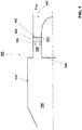
- Figure 1 shows a reheat burner arrangement 100 which incorporates a center body 101.
- the shown center body starts upstream of an injection plane 102 (lobe), causing the fuel 103 and carrier air 104 to be injected into the center body 101, and then the center body continues downstream to the exit 108 of the burner arrangement 100.
- the center body 101 is being actively connected to the main flow 107 of hot gases.
- the center body 101 provides better mixing matches burner and combustor area.
- the center body 101 can be provided with a fuel supply line (not shown).
- the center body 101 exhibits at its end 108 in the flow direction of the main flow 107 a cylindrical or quasi-cylindrical end with respect to the cross-sectional area between the annular duct 105 and the afterwards combustion chamber 109.
- a whole, partial or intermediate conical topography of the center body's surface with respect to the cross sectional area of the annular duct is, as required, also possible.
- the center body 101 with respect to the adjacent elements can be designed with different dimensions, especially with respect to the cross sectional area of the annular duct and the combustion chamber.
- the proposed reheat burner arrangement in Figure 1 is shown with non-reduced exit cross-section area 105 with respect to the combustion chamber 109.
- the center body 101 downstream of an inlet side of the burner arrangement there is located the center body 101 and intermediate in longitudinal direction of the length of the center body 101 and within the cross-section area of the annular duct 105 there is located circumferentially fuel injection planes (lobes) 102, which is given as a streamlined body extending in longitudinal direction.
- Figure 2 shows an assembly of a center body burner 101 in a cross sectional view.
- the front section 201 of the center body burner 101 having with respect to the main flow F1 a flow-compliant rounded front which is cooled by impingement cooling 203, wherein the cooling air for this purpose is supplied through the main air cooling channel 104.
- the extension of the front section 201 in the flow direction 204 includes in radial direction a placement of a number of lobes 102 which are circumferentially disposed.
- the medium flow F2 in longitudinal direction of the gas/fuel-flow channel 105 of the center body burner 101 is connected to the combustion chamber 109.
- the cooling air supplied through the circumferentially disposed main cooling channels 104 flows at high pressure in the cooling volume 209 and strikes against the inner wall 210 of the center body burner 101.
- the cooling air passing through the channels 104 forms a divergently impingement air cooling stream within the cooling volume 209 and impinges on a greater region of the center body burner front section 201.
- the impingement cooling is particularly effective if, according to a preferable proposed embodiment, the impingement cooling inner wall 210 is arranged at a distance parallel to the rear side 211 of the front section 201 of the center body
- the impingement cooling is particularly effective if, according to a preferable proposed embodiment, the impingement cooling inner wall 210 is arranged at a distance parallel to the rear side 211 of the front section 201 of the center body burner 101, and if the distribution of the impingement cooling holes 203 is matched to the distribution of the pins (not shown) within the cavity 212 in such a way that the impingement cooling holes 203 lie between the pins in each case, as seen in a direction perpendicular to the impingement cooling plate.
- the variation of the cooling can be intensified by the density of the impingement cooling holes 203 being correlated with the density of the pins.
- the density of the impingement cooling holes and the density of the pins can locally be the same.
- the cavity 212 which is covered by the impingement cooling inner wall 210 arranged parallel to the front section 201 of the center body burner 101 is formed on the upper side of the front section 201. Provision is made in the impingement cooling inner wall 210, in a pre-specified distribution, for impingement cooling holes 203 through which the compressed cooling air in the form of individual cooling air jets enter the cavity 212 and impinge upon the oppositely disposed rear side 211 of the front section 201 of the center body burner 101.
- the cooling air absorbs heat from the front section 201 of the center body burner 101 and is then discharged from the cavity 212.
- perpendicularly projecting conical or pyramid-shaped pins are arranged on the rear side 211 of the front section 201 of the center body burner 101 and enlarge the contact area between wall and pins is increased (concentrated regions) the density of the impingement cooling holes 203 is also increased, and vice versa.
- the impingement cooling holes 203 are preferably arranged with the pins, if required, in a "staggered” manner that is to saying holes 203 with the same periodicity are positioned in a staggered manner in each case.
- the heat dissipation in the region of the front section 201 of the center body burner 101 is significantly improved, as a result of which the effects of the thermal load can be limited.
- impingement cooling has been described with reference to particular embodiments thereof, it will be understood by those having ordinary skill the art that various changes may be made therein. After the described impingement cooling process the cooling air continues to flow in longitudinal direction of a transition duct 204 in the region of the lobes 102 (middle face), and then this cooling air flows within a subsequently arranged annular channel 213 in longitudinal direction of the back face of the center body burner.
- This transition duct 204 is positioned in axial direction between the outer periphery of a damper 300 and the liner 202 of the back face of the center body burner 101.
- the cooling air from the impingement cooling cools thereafter the middle face (transition duct 204) and subsequently the back face 202 (annular channel) with a convective and/ or an effusion cooling.
- the back face 202 of the center body burner 102 should be preferably cooled by an effusion cooling.
- the plurality of effusion cooling holes 205 are positioned in the outer skin member of the back face 202 preferably at an angle of about 15 to 30
- the plurality of effusion cooling holes 205 are positioned in the outer skin member of the back face 202 preferably at an angle of about 15 to 30 degrees and extend at least of a part of the annular channel 213, and the effusion cooling holes 205 are connected to the mixing space 105. Additional ones of the plurality of effusion cooling holes 205 are positioned in additional rows in longitudinal direction of the transition duct 204.
- the lobes 102 respectively the fuel nozzles 206 are supplied with fuel 103 and further cooling air 207.
- the damper 300 comprising for its operation at least one bore 213 between the cooling volume 209 and the first damper's volume 302a, at least one neck 311 between the first damper's volume 302a and the second damper's volume 303a, at least one passage 304 between the second damper's volume 303b and the combustion chamber 109.
- the center body burner 101 operated in a can-combustor as self-contained cylindrical or quasi-cylindrical combustion chamber.
- each can-combustor has its own fuel injector, igniter, liner, casing, cooling, etc.
- a can-combustor can operate as a self-ignition sequential combustion chamber (SEV).
- SEV self-ignition sequential combustion chamber
- multiple can-combustors are arranged around the central axis of the engine, and their shared exhaust is fed to the turbine(s). Can-combustors are easy to maintain, as only a single can-combustor needs to be removed, rather than the whole combustion section.
- the next type of combustor is the annular-can-combustor.
- the annular-can-combustors architecture has discrete combustion zones contained in separate liners with their own fuel injectors. Unlike the can-combustor, all the combustion zones share a common ring (annulus) casing.
- Figure 3 shows a three dimensional configuration of a damper 300, especially of a low frequency damper.
- an aspect of the embodiment is to provide a damper arrangement and a method for designing same that permit damping of pressure oscillations in a large damping bandwidth, in particular when compared to the bandwidth of traditional damp arrangements made of Helmholtz dampers.
- a further aspect of the proposed arrangement is to provide a damper arrangement that is able to cope with the frequency shifting of the pressure oscillations with no or limited need of fine tuning.
- Another aspect of the proposed arrangement is to provide a damper arrangement that is very simple, in particular when compared to the traditional damper arrangements described above.
- the damper 300 of Figure 3 consists of an inner cylinder 301 and an outer cylinder 312 and the inner cylinder comprising two chambers 302, 303.
- the first chamber 302 defines the first volume 302a and the second chamber 303 defines the second volume 303a.
- the first volume 302a is arranged downstream of the center body 101 and the second volume is arranged upstream of the combustion chamber 109 (see Figures 1 and 2 ).
- the first volume 302a is connected by means of at least one bore 213 (see Figure 2 ) to the cooling air flow within the center body;
- the second volume 303a is connected by means of a passage 304 to the combustion area 109 of the combustion chamber (see Figure 2 ).
- the passage is located eccentrically with respect to the center line 314 of the inner cylinder 301.
- Figure 3 shows that the first volume 302a is delimited by the second volume 303a by a partition wall 305 consisting of two intermediate walls 306, 307.
- the intermediate walls 306, 307 comprising to one another a sealing mat 308.
- the intermediate walls having two alignable holes 309, 310 and at the first volume 302a and the second chamber 303 defines the second volume 303a with variable cross section to defining by the aligned holes 311 of the partition wall 305.
- An outer cylinder 312 takes the assembly to the center body 101 by means of bayonet look 313.
- Figure 4 shows an arrangement where first nozzles 206 for injection of liquid fuel, are enclosed by second nozzles 206a for injection of a gaseous fuel, which themselves are encloses by third nozzles 206b for injection of carrier air.
- the nozzles 206, 206a, 206b are arranged concentrically at the trailing edge of each lobe 102.
- Each nozzle arrangement is located where the flute 401 crosses the center plane of the trailing edge 400 of the lobe (see Fig. 2 ).
Claims (13)
- Brenneranordnung (100) zur Verwendung in einer Einzelbrennkammer oder einer Can-Brennkammer, umfassend einen anströmseitig einer Brennzone oder -kammer (109) angeordneten Zentralkörper-Brenner (101), einen Ringkanal (105) mit einer Querschnittsfläche, Zwischennocken (102), die in Umfangsrichtung und in Längs- oder Quasi-Längsrichtung des Zentralkörper-Brenners (101) angeordnet sind, wobei die Nocken (102) mit der Querschnittsfläche des Ringkanals (105) wirkverbunden sind, Kühlluft durch eine Anzahl von Rohren (104) innerhalb der Nocken (102) zu dem Zentralkörper-Brenner (101) geleitet wird, ein Frontbereich (201) des Zentralkörper-Brenners (101) eine zwischen einer Rückseite (211) des Frontbereichs (201) des Zentralkörper-Brenners (101) und einer Prallkühlungsinnenwand (210) angeordneten Prallkühlungshohlraum (212) aufweist;
wobei die Brenneranordnung so gestaltet ist, dass die Kühlluft aus dem Hohlraum (212) direkt oder indirekt mit einem Übergangskanal (204) in Längsrichtung einer mittleren Fläche und in Längsrichtung eines anschließenden Ringkanals (213) innerhalb einer hinteren Fläche (202) des Zentralkörper-Brenners (101) verbunden ist und dass die Kühlluft aufgrund einer Prallkühlung zunächst mindestens den Frontbereich (201) des Zentralkörper-Brenners (101) kühlt (203), und mit einer anschließenden Strömung kühlt die Prallkühlluft mittels Konvektions- oder Effusionskühlung die mittlere und die hintere Fläche (202) des Zentralkörper-Brenners (101), wobei mindestens die hintere Fläche (202) des Zentralkörper-Brenners (101) im Inneren mindestens einen Dämpfer (300) umfasst. - Brenneranordnung nach Anspruch 1, wobei der Dämpfer (300) als Niederfrequenzdämpfer wirkend ausgeführt ist.
- Brenneranordnung nach Anspruch 1, wobei die Nocken (102) in Strömungsrichtung ein stromlinienförmiges Querschnittsprofil aufweisen und sich in Längsrichtung senkrecht oder schräg zu der vorherrschenden Hauptströmungsrichtung erstrecken, wobei die Vorderkantenfläche jedes Nocken ein zu der vorherrschenden Hauptströmungsrichtung ausgerichtetes stromlinienförmiges Profil aufweist, die Hinterkante jedes Nocken in Bezug auf eine Mittelebene mindestens eine Rille (401) aufweist und die Rillen in Längs- oder Quasi-Längsrichtung aller Nocken in Verbindung miteinander in derselben Richtung und/oder in entgegengesetzten Querrichtungen verlaufen.
- Brenneranordnung nach Anspruch 3, wobei jeder Nocken (102) im Bereich der Hinterkante mindestens eine Brennstoffdüse (206) zum Einleiten mindestens eines Brennstoffs (103) in den Brenner aufweist, wobei die Brennstoffdüse mit der Rille (401) wirkverbunden ist.
- Brenneranordnung nach Anspruch 1, wobei der Vorderkantenbereich des Nocken (102) ein aerodynamisches Profil aufweist, das sich von einer Schrägrichtung relativ zur Längsachse der Strömungsrichtung in eine Richtung wendet, die mindestens in der anströmseitigen Hälfte des Nocken (102) parallel oder quasi-parallel zur Längsrichtung der Strömungsrichtung (107) verläuft.
- Brenneranordnung nach einem der Ansprüche 1 bis 5, wobei der Nocken (102) Kühlelemente aufweist, die vorzugsweise in Form eines inneren Umlaufs des Kühlmediums in Längs- oder Quasi-Längsrichtung der Seitenwände des Nocken (102) und/oder als Filmkühlungsöffnungen ausgeführt sind, welche vorzugsweise nahe der Hinterkante (400) angeordnet sind, wobei den Kühlelementen vorzugsweise Luft aus der Trägergaszuführung zugeführt wird, die auch für die Brennstoffeinspritzung verwendet wird.
- Brenneranordnung nach einem der Ansprüche 1 bis 6, wobei die Brennstoffdüsen (207) kreisförmige und/oder längliche Schlitzdüsen sind, die sich in Längsrichtung oder Quasi-Längsrichtung der Hinterkante des stromlinienförmigen Körpers erstrecken und/oder eine erste Düse (206) zur Einspritzung einer Flüssigkeit, eine zweite Düse (206a) zur Einspritzung eines gasförmigen Brennstoffs und eine dritte Düse (206b) zur Einspritzung von Trägerluft umfassen, welche die erste und/oder die zweite Düse umschließt.
- Brenneranordnung nach einem der Ansprüche 1 bis 7, wobei der Ringkanal (105) abströmseitig der Nocken (102) eine Mischzone bildet und der Querschnitt der Mischzone (105) abströmseitig und/oder an den Nocken (102) reduziert ist, wobei die Reduzierung im Vergleich zu dem Strömungsquerschnitt anströmseitig der Nocken bevorzugt mindestens 10%, noch bevorzugter mindestens 20% und noch bevorzugter mindestens 30% beträgt.
- Brenneranordnung nach einem der Ansprüche 1 bis 7, wobei der Ringkanal (105) abströmseitig der Nocken (102) eine Mischzone bildet und der Querschnitt der Mischzone (105) abströmseitig und/oder an den Nocken (102) erweitert ist, wobei die Erweiterung im Vergleich zu dem Strömungsquerschnitt anströmseitig der Nocken bevorzugt mindestens 10%, noch bevorzugter mindestens 20% und noch bevorzugter mindestens 30% beträgt.
- Brenneranordnung nach einem der Ansprüche 1 bis 7, wobei der Ringkanal abströmseitig der Nocken (102) eine Mischzone bildet und der Querschnitt der Mischzone (105) abströmseitig und/oder an den Nocken (102) die Form eines Diffusors hat.
- Brenneranordnung nach einem der Ansprüche 1 bis 10, wobei mindestens für einen Brenner für eine Brennkammer einer Gasturbinengruppe mindestens eine Einspritzebene verwendet wird, die Gasturbinengruppe mindestens eine Verdichtereinheit und eine erste Brennkammer zur Erzeugung des Arbeitsgases umfasst, wobei die erste Brennkammer so verbunden ist, dass sie Druckluft von der Verdichtereinheit empfängt, wobei die erste Brennkammer eine Ringbrennkammer mit einer Vielzahl von Vormischbrennern ist, eine erste Turbine so verbunden ist, dass sie Arbeitsgas aus der ersten Brennkammer empfängt, eine zweite Brennkammer so verbunden ist, dass sie Arbeitsabgas von der ersten Turbine empfängt und der zweiten Turbine Arbeitsgas zuführt, wobei die zweite Brennkammer einen Ringkanal umfasst, der einen sich in einer Strömungsrichtung vom Austritt der ersten Turbine zu einem Eintritt der zweiten Turbine erstreckenden Brennraum bildet, wobei die zweite Brennkammer Vorrichtungen zum Einspritzen von Brennstoff in die zweite Brennkammer zur Selbstzündung des Brennstoffs umfasst.
- Brenneranordnung nach einem der Ansprüche 1 bis 10, wobei mindestens für einen Brenner für eine Brennkammer einer Gasturbinengruppe mindestens eine Einspritzebene verwendet wird, die Gasturbinengruppe mindestens eine Verdichtereinheit und eine erste Brennkammer zur Erzeugung des Arbeitsgases umfasst, wobei die erste Brennkammer so verbunden ist, dass sie Druckluft von der Verdichtereinheit empfängt, wobei die erste Brennkammer eine Ringbrennkammer mit einer Vielzahl von Vormischbrennern ist, eine erste Turbine so verbunden ist, dass sie Arbeitsgas aus der ersten Brennkammer empfängt, eine zweite Brennkammer so verbunden ist, dass sie Arbeitsabgas von der ersten Turbine empfängt und der zweiten Turbine Arbeitsgas zuführt, wobei die zweite Brennkammer als Can-Brennkammer betrieben wird, die als in sich abgeschlossene zylindrische oder quasi-zylindrische Brennkammer ausgeführt ist, wobei die Can-Brennkammer Vorrichtungen zum Einspritzen von Brennstoff in die zweite Brennkammer zur Selbstzündung des Brennstoffs umfasst.
- Brenneranordnung nach Anspruch 12, wobei um die Mittelachse der Gasturbinengruppe mehrere Can-Brennkammern angeordnet sind.
Priority Applications (7)
| Application Number | Priority Date | Filing Date | Title |
|---|---|---|---|
| EP13180642.4A EP2837883B1 (de) | 2013-08-16 | 2013-08-16 | Vorgemischter Rohrbrenner mit wellenförmigen Vormischflügeln für die zweite Stufe einer sequentiellen Gasturbine |
| US14/445,485 US9829200B2 (en) | 2013-08-16 | 2014-07-29 | Burner arrangement and method for operating a burner arrangement |
| KR20140105739A KR20150020135A (ko) | 2013-08-16 | 2014-08-14 | 버너 장치 및 버너 장치를 작동하기 위한 방법 |
| RU2014133525A RU2665199C2 (ru) | 2013-08-16 | 2014-08-14 | Горелочное устройство и способ работы горелочного устройства |
| CA2859435A CA2859435A1 (en) | 2013-08-16 | 2014-08-15 | Burner arrangement and method for operating a burner arrangement |
| CN201410402172.1A CN104373961B (zh) | 2013-08-16 | 2014-08-15 | 喷燃器布置及用于操作喷燃器布置的方法 |
| JP2014165779A JP2015036554A (ja) | 2013-08-16 | 2014-08-18 | バーナ配列およびバーナ配列を作動させる方法 |
Applications Claiming Priority (1)
| Application Number | Priority Date | Filing Date | Title |
|---|---|---|---|
| EP13180642.4A EP2837883B1 (de) | 2013-08-16 | 2013-08-16 | Vorgemischter Rohrbrenner mit wellenförmigen Vormischflügeln für die zweite Stufe einer sequentiellen Gasturbine |
Publications (2)
| Publication Number | Publication Date |
|---|---|
| EP2837883A1 EP2837883A1 (de) | 2015-02-18 |
| EP2837883B1 true EP2837883B1 (de) | 2018-04-04 |
Family
ID=48998491
Family Applications (1)
| Application Number | Title | Priority Date | Filing Date |
|---|---|---|---|
| EP13180642.4A Active EP2837883B1 (de) | 2013-08-16 | 2013-08-16 | Vorgemischter Rohrbrenner mit wellenförmigen Vormischflügeln für die zweite Stufe einer sequentiellen Gasturbine |
Country Status (7)
| Country | Link |
|---|---|
| US (1) | US9829200B2 (de) |
| EP (1) | EP2837883B1 (de) |
| JP (1) | JP2015036554A (de) |
| KR (1) | KR20150020135A (de) |
| CN (1) | CN104373961B (de) |
| CA (1) | CA2859435A1 (de) |
| RU (1) | RU2665199C2 (de) |
Families Citing this family (13)
| Publication number | Priority date | Publication date | Assignee | Title |
|---|---|---|---|---|
| EP2886955A1 (de) * | 2013-12-17 | 2015-06-24 | Siemens Aktiengesellschaft | Kalibriermittel zur Luftdurchflussjustierung für den Drallerzeuger eines Gasturbinenbrenners |
| US10598382B2 (en) * | 2014-11-07 | 2020-03-24 | United Technologies Corporation | Impingement film-cooled floatwall with backside feature |
| US9989260B2 (en) * | 2015-12-22 | 2018-06-05 | General Electric Company | Staged fuel and air injection in combustion systems of gas turbines |
| US10718523B2 (en) * | 2017-05-12 | 2020-07-21 | General Electric Company | Fuel injectors with multiple outlet slots for use in gas turbine combustor |
| US11242806B2 (en) * | 2017-11-20 | 2022-02-08 | Power Systems Mfg., Llc | Method of controlling fuel injection in a reheat combustor for a combustor unit of a gas turbine |
| EP3663548B1 (de) * | 2018-12-06 | 2022-05-25 | Ansaldo Energia Switzerland AG | Dämpfer für eine brennkammeranordnung eines gasturbinenkraftwerks und brennkammeranordnung mit dem dämpfer |
| US11156164B2 (en) | 2019-05-21 | 2021-10-26 | General Electric Company | System and method for high frequency accoustic dampers with caps |
| US11174792B2 (en) | 2019-05-21 | 2021-11-16 | General Electric Company | System and method for high frequency acoustic dampers with baffles |
| EP3748231B1 (de) * | 2019-06-05 | 2023-08-30 | Siemens Energy Global GmbH & Co. KG | Brenner und brennerspitze |
| US11506382B2 (en) * | 2019-09-12 | 2022-11-22 | General Electric Company | System and method for acoustic dampers with multiple volumes in a combustion chamber front panel |
| US11560837B2 (en) * | 2021-04-19 | 2023-01-24 | General Electric Company | Combustor dilution hole |
| CN113606609B (zh) * | 2021-07-19 | 2022-10-11 | 南京航空航天大学 | 基于中心台阶点火的组合稳定器及其工作方法 |
| CN114017773B (zh) * | 2021-12-16 | 2022-04-22 | 东营市悦凯石油装备有限公司 | 一种燃气发电机组用新型防回火燃气混合器 |
Family Cites Families (22)
| Publication number | Priority date | Publication date | Assignee | Title |
|---|---|---|---|---|
| US2979899A (en) * | 1953-06-27 | 1961-04-18 | Snecma | Flame spreading device for combustion equipments |
| CH674561A5 (de) | 1987-12-21 | 1990-06-15 | Bbc Brown Boveri & Cie | |
| CH680816A5 (de) * | 1989-04-27 | 1992-11-13 | Asea Brown Boveri | |
| DE59208193D1 (de) | 1992-07-03 | 1997-04-17 | Abb Research Ltd | Nachbrenner |
| EP0592717B1 (de) * | 1992-10-16 | 1998-02-25 | Asea Brown Boveri Ag | Gasbetriebener Vormischbrenner |
| US5385015A (en) * | 1993-07-02 | 1995-01-31 | United Technologies Corporation | Augmentor burner |
| DE4426351B4 (de) | 1994-07-25 | 2006-04-06 | Alstom | Brennkammer für eine Gasturbine |
| US5511375A (en) * | 1994-09-12 | 1996-04-30 | General Electric Company | Dual fuel mixer for gas turbine combustor |
| US6082111A (en) | 1998-06-11 | 2000-07-04 | Siemens Westinghouse Power Corporation | Annular premix section for dry low-NOx combustors |
| DE10128063A1 (de) | 2001-06-09 | 2003-01-23 | Alstom Switzerland Ltd | Brennersystem |
| US7080515B2 (en) | 2002-12-23 | 2006-07-25 | Siemens Westinghouse Power Corporation | Gas turbine can annular combustor |
| US8607569B2 (en) * | 2009-07-01 | 2013-12-17 | General Electric Company | Methods and systems to thermally protect fuel nozzles in combustion systems |
| US8789372B2 (en) * | 2009-07-08 | 2014-07-29 | General Electric Company | Injector with integrated resonator |
| EP2496882B1 (de) | 2009-11-07 | 2018-03-28 | Ansaldo Energia Switzerland AG | Injektionssystem mit brennstofflanzen für einen nachbrenner |
| RU2550370C2 (ru) * | 2011-05-11 | 2015-05-10 | Альстом Текнолоджи Лтд | Центробежная форсунка с выступающими частями |
| US8938971B2 (en) * | 2011-05-11 | 2015-01-27 | Alstom Technology Ltd | Flow straightener and mixer |
| RU122447U1 (ru) * | 2012-06-25 | 2012-11-27 | Открытое акционерное общество Конструкторско-производственное предприятие "Авиамотор" | Газотурбинный двигатель гтд-25ста, компрессор, камера сгорания, турбина газогенератора, свободная турбина |
| CA2830031C (en) * | 2012-10-23 | 2016-03-15 | Alstom Technology Ltd. | Burner for a can combustor |
| EP2725302A1 (de) * | 2012-10-25 | 2014-04-30 | Alstom Technology Ltd | Nachbrenneranordnung |
| EP2837888A1 (de) * | 2013-08-15 | 2015-02-18 | Alstom Technology Ltd | Sequentielle Verbrennung mit Verdünnungsgasmischer |
| EP3023696B1 (de) * | 2014-11-20 | 2019-08-28 | Ansaldo Energia Switzerland AG | Nockenlanze für eine Gasturbinenbrennkammer |
| EP3026344B1 (de) * | 2014-11-26 | 2019-05-22 | Ansaldo Energia Switzerland AG | Brenner einer Gasturbine |
-
2013
- 2013-08-16 EP EP13180642.4A patent/EP2837883B1/de active Active
-
2014
- 2014-07-29 US US14/445,485 patent/US9829200B2/en active Active
- 2014-08-14 KR KR20140105739A patent/KR20150020135A/ko not_active Application Discontinuation
- 2014-08-14 RU RU2014133525A patent/RU2665199C2/ru active
- 2014-08-15 CA CA2859435A patent/CA2859435A1/en active Pending
- 2014-08-15 CN CN201410402172.1A patent/CN104373961B/zh active Active
- 2014-08-18 JP JP2014165779A patent/JP2015036554A/ja active Pending
Non-Patent Citations (1)
| Title |
|---|
| None * |
Also Published As
| Publication number | Publication date |
|---|---|
| EP2837883A1 (de) | 2015-02-18 |
| CN104373961A (zh) | 2015-02-25 |
| KR20150020135A (ko) | 2015-02-25 |
| US20150047364A1 (en) | 2015-02-19 |
| CA2859435A1 (en) | 2015-02-16 |
| JP2015036554A (ja) | 2015-02-23 |
| RU2665199C2 (ru) | 2018-08-28 |
| CN104373961B (zh) | 2018-10-02 |
| US9829200B2 (en) | 2017-11-28 |
| RU2014133525A (ru) | 2016-03-10 |
Similar Documents
| Publication | Publication Date | Title |
|---|---|---|
| EP2837883B1 (de) | Vorgemischter Rohrbrenner mit wellenförmigen Vormischflügeln für die zweite Stufe einer sequentiellen Gasturbine | |
| EP2522912B1 (de) | Strömungsgleichrichter und Mischer | |
| EP2496884B1 (de) | Injektionssystem für einen nachbrenner | |
| US9810152B2 (en) | Gas turbine combustion system | |
| EP2496880B1 (de) | Injektionssystem für einen nachbrenner | |
| US9664390B2 (en) | Burner arrangement including an air supply with two flow passages | |
| EP2496882B1 (de) | Injektionssystem mit brennstofflanzen für einen nachbrenner | |
| EP2496885B1 (de) | Brenner mit einem kühlsystem für erhöhte gasturbineneffizienz | |
| US6675587B2 (en) | Counter swirl annular combustor | |
| EP2496883B1 (de) | Vormischrbrenner für einen gasturbinenbrenner | |
| KR20160060565A (ko) | 순차적 연소를 갖는 가스 터빈을 위한 연료 랜싯 냉각 |
Legal Events
| Date | Code | Title | Description |
|---|---|---|---|
| 17P | Request for examination filed |
Effective date: 20130816 |
|
| AK | Designated contracting states |
Kind code of ref document: A1 Designated state(s): AL AT BE BG CH CY CZ DE DK EE ES FI FR GB GR HR HU IE IS IT LI LT LU LV MC MK MT NL NO PL PT RO RS SE SI SK SM TR |
|
| AX | Request for extension of the european patent |
Extension state: BA ME |
|
| PUAI | Public reference made under article 153(3) epc to a published international application that has entered the european phase |
Free format text: ORIGINAL CODE: 0009012 |
|
| RAP1 | Party data changed (applicant data changed or rights of an application transferred) |
Owner name: GENERAL ELECTRIC TECHNOLOGY GMBH |
|
| 17Q | First examination report despatched |
Effective date: 20161110 |
|
| RAP1 | Party data changed (applicant data changed or rights of an application transferred) |
Owner name: ANSALDO ENERGIA SWITZERLAND AG |
|
| GRAP | Despatch of communication of intention to grant a patent |
Free format text: ORIGINAL CODE: EPIDOSNIGR1 |
|
| INTG | Intention to grant announced |
Effective date: 20171024 |
|
| GRAS | Grant fee paid |
Free format text: ORIGINAL CODE: EPIDOSNIGR3 |
|
| GRAA | (expected) grant |
Free format text: ORIGINAL CODE: 0009210 |
|
| AK | Designated contracting states |
Kind code of ref document: B1 Designated state(s): AL AT BE BG CH CY CZ DE DK EE ES FI FR GB GR HR HU IE IS IT LI LT LU LV MC MK MT NL NO PL PT RO RS SE SI SK SM TR |
|
| REG | Reference to a national code |
Ref country code: GB Ref legal event code: FG4D |
|
| REG | Reference to a national code |
Ref country code: CH Ref legal event code: EP |
|
| REG | Reference to a national code |
Ref country code: AT Ref legal event code: REF Ref document number: 985978 Country of ref document: AT Kind code of ref document: T Effective date: 20180415 |
|
| REG | Reference to a national code |
Ref country code: IE Ref legal event code: FG4D |
|
| REG | Reference to a national code |
Ref country code: DE Ref legal event code: R096 Ref document number: 602013035310 Country of ref document: DE |
|
| REG | Reference to a national code |
Ref country code: NL Ref legal event code: MP Effective date: 20180404 |
|
| REG | Reference to a national code |
Ref country code: LT Ref legal event code: MG4D |
|
| PG25 | Lapsed in a contracting state [announced via postgrant information from national office to epo] |
Ref country code: NL Free format text: LAPSE BECAUSE OF FAILURE TO SUBMIT A TRANSLATION OF THE DESCRIPTION OR TO PAY THE FEE WITHIN THE PRESCRIBED TIME-LIMIT Effective date: 20180404 |
|
| PG25 | Lapsed in a contracting state [announced via postgrant information from national office to epo] |
Ref country code: AL Free format text: LAPSE BECAUSE OF FAILURE TO SUBMIT A TRANSLATION OF THE DESCRIPTION OR TO PAY THE FEE WITHIN THE PRESCRIBED TIME-LIMIT Effective date: 20180404 Ref country code: BG Free format text: LAPSE BECAUSE OF FAILURE TO SUBMIT A TRANSLATION OF THE DESCRIPTION OR TO PAY THE FEE WITHIN THE PRESCRIBED TIME-LIMIT Effective date: 20180704 Ref country code: SE Free format text: LAPSE BECAUSE OF FAILURE TO SUBMIT A TRANSLATION OF THE DESCRIPTION OR TO PAY THE FEE WITHIN THE PRESCRIBED TIME-LIMIT Effective date: 20180404 Ref country code: FI Free format text: LAPSE BECAUSE OF FAILURE TO SUBMIT A TRANSLATION OF THE DESCRIPTION OR TO PAY THE FEE WITHIN THE PRESCRIBED TIME-LIMIT Effective date: 20180404 Ref country code: PL Free format text: LAPSE BECAUSE OF FAILURE TO SUBMIT A TRANSLATION OF THE DESCRIPTION OR TO PAY THE FEE WITHIN THE PRESCRIBED TIME-LIMIT Effective date: 20180404 Ref country code: NO Free format text: LAPSE BECAUSE OF FAILURE TO SUBMIT A TRANSLATION OF THE DESCRIPTION OR TO PAY THE FEE WITHIN THE PRESCRIBED TIME-LIMIT Effective date: 20180704 Ref country code: ES Free format text: LAPSE BECAUSE OF FAILURE TO SUBMIT A TRANSLATION OF THE DESCRIPTION OR TO PAY THE FEE WITHIN THE PRESCRIBED TIME-LIMIT Effective date: 20180404 Ref country code: LT Free format text: LAPSE BECAUSE OF FAILURE TO SUBMIT A TRANSLATION OF THE DESCRIPTION OR TO PAY THE FEE WITHIN THE PRESCRIBED TIME-LIMIT Effective date: 20180404 |
|
| PG25 | Lapsed in a contracting state [announced via postgrant information from national office to epo] |
Ref country code: HR Free format text: LAPSE BECAUSE OF FAILURE TO SUBMIT A TRANSLATION OF THE DESCRIPTION OR TO PAY THE FEE WITHIN THE PRESCRIBED TIME-LIMIT Effective date: 20180404 Ref country code: GR Free format text: LAPSE BECAUSE OF FAILURE TO SUBMIT A TRANSLATION OF THE DESCRIPTION OR TO PAY THE FEE WITHIN THE PRESCRIBED TIME-LIMIT Effective date: 20180705 Ref country code: LV Free format text: LAPSE BECAUSE OF FAILURE TO SUBMIT A TRANSLATION OF THE DESCRIPTION OR TO PAY THE FEE WITHIN THE PRESCRIBED TIME-LIMIT Effective date: 20180404 Ref country code: RS Free format text: LAPSE BECAUSE OF FAILURE TO SUBMIT A TRANSLATION OF THE DESCRIPTION OR TO PAY THE FEE WITHIN THE PRESCRIBED TIME-LIMIT Effective date: 20180404 |
|
| REG | Reference to a national code |
Ref country code: AT Ref legal event code: MK05 Ref document number: 985978 Country of ref document: AT Kind code of ref document: T Effective date: 20180404 |
|
| PG25 | Lapsed in a contracting state [announced via postgrant information from national office to epo] |
Ref country code: PT Free format text: LAPSE BECAUSE OF FAILURE TO SUBMIT A TRANSLATION OF THE DESCRIPTION OR TO PAY THE FEE WITHIN THE PRESCRIBED TIME-LIMIT Effective date: 20180806 |
|
| REG | Reference to a national code |
Ref country code: DE Ref legal event code: R097 Ref document number: 602013035310 Country of ref document: DE |
|
| PG25 | Lapsed in a contracting state [announced via postgrant information from national office to epo] |
Ref country code: RO Free format text: LAPSE BECAUSE OF FAILURE TO SUBMIT A TRANSLATION OF THE DESCRIPTION OR TO PAY THE FEE WITHIN THE PRESCRIBED TIME-LIMIT Effective date: 20180404 Ref country code: CZ Free format text: LAPSE BECAUSE OF FAILURE TO SUBMIT A TRANSLATION OF THE DESCRIPTION OR TO PAY THE FEE WITHIN THE PRESCRIBED TIME-LIMIT Effective date: 20180404 Ref country code: EE Free format text: LAPSE BECAUSE OF FAILURE TO SUBMIT A TRANSLATION OF THE DESCRIPTION OR TO PAY THE FEE WITHIN THE PRESCRIBED TIME-LIMIT Effective date: 20180404 Ref country code: AT Free format text: LAPSE BECAUSE OF FAILURE TO SUBMIT A TRANSLATION OF THE DESCRIPTION OR TO PAY THE FEE WITHIN THE PRESCRIBED TIME-LIMIT Effective date: 20180404 Ref country code: DK Free format text: LAPSE BECAUSE OF FAILURE TO SUBMIT A TRANSLATION OF THE DESCRIPTION OR TO PAY THE FEE WITHIN THE PRESCRIBED TIME-LIMIT Effective date: 20180404 Ref country code: SK Free format text: LAPSE BECAUSE OF FAILURE TO SUBMIT A TRANSLATION OF THE DESCRIPTION OR TO PAY THE FEE WITHIN THE PRESCRIBED TIME-LIMIT Effective date: 20180404 |
|
| PLBE | No opposition filed within time limit |
Free format text: ORIGINAL CODE: 0009261 |
|
| STAA | Information on the status of an ep patent application or granted ep patent |
Free format text: STATUS: NO OPPOSITION FILED WITHIN TIME LIMIT |
|
| PG25 | Lapsed in a contracting state [announced via postgrant information from national office to epo] |
Ref country code: SM Free format text: LAPSE BECAUSE OF FAILURE TO SUBMIT A TRANSLATION OF THE DESCRIPTION OR TO PAY THE FEE WITHIN THE PRESCRIBED TIME-LIMIT Effective date: 20180404 |
|
| 26N | No opposition filed |
Effective date: 20190107 |
|
| PG25 | Lapsed in a contracting state [announced via postgrant information from national office to epo] |
Ref country code: MC Free format text: LAPSE BECAUSE OF FAILURE TO SUBMIT A TRANSLATION OF THE DESCRIPTION OR TO PAY THE FEE WITHIN THE PRESCRIBED TIME-LIMIT Effective date: 20180404 |
|
| REG | Reference to a national code |
Ref country code: CH Ref legal event code: PL |
|
| PG25 | Lapsed in a contracting state [announced via postgrant information from national office to epo] |
Ref country code: LI Free format text: LAPSE BECAUSE OF NON-PAYMENT OF DUE FEES Effective date: 20180831 Ref country code: CH Free format text: LAPSE BECAUSE OF NON-PAYMENT OF DUE FEES Effective date: 20180831 Ref country code: LU Free format text: LAPSE BECAUSE OF NON-PAYMENT OF DUE FEES Effective date: 20180816 |
|
| REG | Reference to a national code |
Ref country code: BE Ref legal event code: MM Effective date: 20180831 |
|
| REG | Reference to a national code |
Ref country code: IE Ref legal event code: MM4A |
|
| PG25 | Lapsed in a contracting state [announced via postgrant information from national office to epo] |
Ref country code: SI Free format text: LAPSE BECAUSE OF FAILURE TO SUBMIT A TRANSLATION OF THE DESCRIPTION OR TO PAY THE FEE WITHIN THE PRESCRIBED TIME-LIMIT Effective date: 20180404 |
|
| PG25 | Lapsed in a contracting state [announced via postgrant information from national office to epo] |
Ref country code: IE Free format text: LAPSE BECAUSE OF NON-PAYMENT OF DUE FEES Effective date: 20180816 |
|
| PG25 | Lapsed in a contracting state [announced via postgrant information from national office to epo] |
Ref country code: BE Free format text: LAPSE BECAUSE OF NON-PAYMENT OF DUE FEES Effective date: 20180831 Ref country code: FR Free format text: LAPSE BECAUSE OF NON-PAYMENT OF DUE FEES Effective date: 20180831 |
|
| PG25 | Lapsed in a contracting state [announced via postgrant information from national office to epo] |
Ref country code: MT Free format text: LAPSE BECAUSE OF NON-PAYMENT OF DUE FEES Effective date: 20180816 |
|
| PG25 | Lapsed in a contracting state [announced via postgrant information from national office to epo] |
Ref country code: TR Free format text: LAPSE BECAUSE OF FAILURE TO SUBMIT A TRANSLATION OF THE DESCRIPTION OR TO PAY THE FEE WITHIN THE PRESCRIBED TIME-LIMIT Effective date: 20180404 |
|
| PG25 | Lapsed in a contracting state [announced via postgrant information from national office to epo] |
Ref country code: HU Free format text: LAPSE BECAUSE OF FAILURE TO SUBMIT A TRANSLATION OF THE DESCRIPTION OR TO PAY THE FEE WITHIN THE PRESCRIBED TIME-LIMIT; INVALID AB INITIO Effective date: 20130816 |
|
| PG25 | Lapsed in a contracting state [announced via postgrant information from national office to epo] |
Ref country code: CY Free format text: LAPSE BECAUSE OF FAILURE TO SUBMIT A TRANSLATION OF THE DESCRIPTION OR TO PAY THE FEE WITHIN THE PRESCRIBED TIME-LIMIT Effective date: 20180404 Ref country code: MK Free format text: LAPSE BECAUSE OF NON-PAYMENT OF DUE FEES Effective date: 20180404 |
|
| PG25 | Lapsed in a contracting state [announced via postgrant information from national office to epo] |
Ref country code: IS Free format text: LAPSE BECAUSE OF FAILURE TO SUBMIT A TRANSLATION OF THE DESCRIPTION OR TO PAY THE FEE WITHIN THE PRESCRIBED TIME-LIMIT Effective date: 20180804 |
|
| PGFP | Annual fee paid to national office [announced via postgrant information from national office to epo] |
Ref country code: GB Payment date: 20231220 Year of fee payment: 11 |
|
| PGFP | Annual fee paid to national office [announced via postgrant information from national office to epo] |
Ref country code: IT Payment date: 20231228 Year of fee payment: 11 Ref country code: DE Payment date: 20231214 Year of fee payment: 11 |