EP0745732B1 - Cantilever balcony plate element preventing cold bridging - Google Patents
Cantilever balcony plate element preventing cold bridging Download PDFInfo
- Publication number
- EP0745732B1 EP0745732B1 EP96108395A EP96108395A EP0745732B1 EP 0745732 B1 EP0745732 B1 EP 0745732B1 EP 96108395 A EP96108395 A EP 96108395A EP 96108395 A EP96108395 A EP 96108395A EP 0745732 B1 EP0745732 B1 EP 0745732B1
- Authority
- EP
- European Patent Office
- Prior art keywords
- joint element
- openings
- element according
- cantilever slab
- cross
- Prior art date
- Legal status (The legal status is an assumption and is not a legal conclusion. Google has not performed a legal analysis and makes no representation as to the accuracy of the status listed.)
- Expired - Lifetime
Links
Images
Classifications
-
- E—FIXED CONSTRUCTIONS
- E04—BUILDING
- E04B—GENERAL BUILDING CONSTRUCTIONS; WALLS, e.g. PARTITIONS; ROOFS; FLOORS; CEILINGS; INSULATION OR OTHER PROTECTION OF BUILDINGS
- E04B1/00—Constructions in general; Structures which are not restricted either to walls, e.g. partitions, or floors or ceilings or roofs
- E04B1/003—Balconies; Decks
- E04B1/0038—Anchoring devices specially adapted therefor with means for preventing cold bridging
Definitions
- the invention relates to a cantilever panel and / or joint element for reinforced building structures, consisting of one designed to accommodate tension and / or compression reinforcement elements Structure and shear force rods used or usable in this structure, the Shear force bars a middle section engaging in the structure and on both sides of the structure have protruding sections.
- a cantilever plate element has also been proposed (EP-A-0 117 897), in which a Insulating body consists of an upper and a lower part, with reinforcement elements on the upper part can be inserted and pressure elements can be installed on the lower part.
- the top and bottom are pluggable.
- the tensile reinforcement elements must be finished on the underside of the upper part be installed and the same applies to the shear bars. Only then can the top with corresponding pins or the like are inserted into the lower part. So it takes from the outset a correspondingly firm connection of the train reinforcement elements in the corresponding grooves of the upper part to this overall unit from above in the To be able to insert the lower part.
- Cantilever plate element predetermined a certain length, it being at most conceivable that cut parts to be put together, which, however, again becomes an unnecessary Material costs leads.
- the present invention has for its object a cantilever and / or joint element to create the type mentioned, which in a relatively small pitch to the required Length can be produced and in which a simple mounting of the shear bars is realized.
- the structure consists of several, in the longitudinal direction successive components, which with their side facing each other Connect boundary surfaces to each other and form and / or to form the building are non-positively connected to each other, and that the shear bars with their central portion in enclosed by the facing, lateral boundary surfaces, in front of the Joining the components groove-shaped through openings can be used or used are.
- the through openings for receiving the central portion of the Shear bars according to a course that may be oriented obliquely to the horizontal corresponding to it run obliquely to the horizontal. Since the through openings for Inclusion of the central sections of the shear bars by appropriate formation of a groove a lateral border can be produced, practically any shape or any course of the through openings can be chosen, because the shear bars across Level of the lateral boundary surfaces can be inserted.
- the areas of the through openings have a smaller cross section are dimensioned according to the cross section of the central section of the transverse force bars or at least one area approximately adapted to the diameter of the transverse force rods square cross section is provided.
- the successive components can be joined together without any problems because the shear bars to be used in each case already by pressing into the existing groove and held in place. It So all that is required is a flat end on the front of this groove in order to Shear bars just circumferentially closed by forming a circumferentially closed through opening to keep.
- the area of Through opening with the larger cross section seen in the longitudinal extent of the building only extends in the direction of the groove formed in the one lateral boundary surface. So it is even with a corresponding cross-sectional expansion in different sections of the Through opening only in a lateral boundary surface a correspondingly larger Deepening or a correspondingly larger groove cross section available, since the opposite Boundary surface can also be executed in such a case.
- the level Boundary surface therefore bears against the inserted shear bar over the entire length, whereas for example, the transverse force rod only in the areas at the outer end regions of the groove is held with the smaller cross section.
- each component on one side Boundary surface of each component one in the horizontal direction, i.e. across the front of each Component extending spring with dovetail undercuts and on the opposite lateral boundary surface of a corresponding cross-section Groove is formed. This is a constructively very simple, but effective mutual Connection of the successive components possible.
- the components are elastic in this respect deformable material are manufactured as the coupling elements provided with undercuts transversely to the course of the undercuts can be plugged together and in their positive Snap the position into place.
- the special choice of materials for the components means that Undercuts formed nose-like parts elastically deformable, so that the Possibility is given to see this tongue and groove connection also in the longitudinal direction of the building to be plugged together, the projecting lugs being pushed back elastically and then snap back in place. This can cause threading into Longitudinal extension of the groove or tongue can be avoided.
- the components have horizontal grooves near their upper and / or lower edges, being a cross-sectionally U-shaped rail as the upper and / or lower end of the structure is provided, which is formed on its two legs and directed inwards Ridges engage in the grooves on the components.
- a cantilever plate element which at reinforced building structures at the transition between a ceiling slab and a cantilevered one Plate, e.g. a balcony slab is used.
- a cantilevered one Plate e.g. a balcony slab is used.
- the measures described are the same Can also be used for joint elements where it is usually a matter of between Ceiling sections bring heat and sound insulation elements. Even with such Use cases include tensile and / or pressure reinforcement elements as well Use shear bars.
- a structure 1 which consists of a heat-insulating foam or another heat-insulating or soundproofing Material is made.
- the structure 1 serves to accommodate tension and / or compression reinforcement elements, which can be inserted into through openings 2.
- the construction shown is used in the area of the through openings tubular body 3, which for example made of plastic. Through this tubular body 3 and those formed by them Through openings 2 can be a ceiling panel and the adjoining projecting reinforcement elements in the tensile and pressure areas be inserted. This means there are no interruptions in the reinforcement.
- shear bars 4 which are oblique to the horizontal extending middle section 5 and each running straight on both sides of the building body 1 Have area 6, 7. These areas 6, 7 run axially parallel to the central axis 8, 9 of the Through openings 2 or the corresponding tubular body 3.
- the components 10 are each approximately in the middle Through openings 2 available.
- the tubular body 3 have several spaced apart arranged, circumferential ribs 17, so that the tubular body 3 is not on the entire surface Inner wall of the through openings 2 come to rest. This makes it a relatively easy one
- the tubular body 3 can be inserted into the through openings 2, with the ribs 17 an appropriate bracket can still be done without additional gluing or the like.
- a Stop rib 18 is provided which has a larger diameter than the ribs 17 having.
- one or several additional ribs 19 are provided, which result in a correspondingly good locking in the serve filled concrete. If it is also required that the inserted into the tubular body 3 Tension or compression reinforcement elements are completely enclosed with concrete, then one is required Possibility to escape excess air bubbles in the area of the tubular body 3. To this example, one or more holes 20 can be provided for this purpose, via which the Air bubbles can escape into the annular space between two ribs 17.
- the structure 1 is composed of several, one on top of the other in the longitudinal direction following components 10 manufactured.
- the successive components 10 are with the side Boundary surfaces 32, 33 face each other and directly adjoin one another.
- the Shear force bars 4 are with their central section 5 in from the mutually facing, lateral boundary surfaces 32, 33 enclosed through openings used, which in front the assembly of the components are formed as a groove 11.
- the groove 11 which finally forms the through opening corresponds to the course of the Middle section 5 of the transverse force rods 4 executed. So if - as usually provided - the Center section 5 of the transverse force rods 4 is oriented obliquely to the horizontal, then also runs the groove 11 at a corresponding angle. That of the neighboring ones lateral boundary surfaces 32, 33 of the components 10 including through openings 34 have different cross-sectional dimensions with respect to their longitudinal extent.
- the two regions 35, 36 lying near the surface of the finished building body 1 are in cross section is made smaller than the central region 37. Therefore, the one to be inserted into the groove 11 Middle section 5 of the transverse force rod 4 is kept particularly fixed only in the areas 35 and 36, which is sufficient for proper mounting. To press or press the Middle section 5 in the groove 11, therefore, lower forces are required, and it is therefore very simply carry out a corresponding manual assembly.
- the areas 35 and 36 are the cross section of the central section 5 of the transverse force rods 4 adjusted accordingly or designed so that the central section 5 alone at Push in like a corresponding fit is held in a positive and non-positive manner.
- the region 37 of the groove 11 with the larger cross section extends only in the direction of one Component 10, so that on the opposite side acting over the entire length Support is provided by the next component.
- lateral boundary surfaces 32, 33 additional recording options for tension and / or pressure reinforcement elements to create which, for example in the manner of a plug iron, already at the Assembly of the cantilever panel element could also be inserted.
- a shear force lie in one plane or else are arranged correspondingly offset from one another.
- protruding webs are formed on the opposite boundary surface which then engage in the opposite grooves on the next component 10, to reduce the cross section formed by the groove itself for the through opening 34 and pinch any reinforcement element that may have been inserted.
- the components 10 are made of an elastically deformable material, for example one expanded foam or other heat insulating material. Components from such Materials are elastically deformable within certain limits. With the components provided here goes the elastic deformability just as far as those provided with undercuts 38, 39 Coupling elements transverse to the course of these springs 12 and grooves 13 or the undercuts 38, 39 can be plugged onto one another, in which case the undercuts 38, 39 formed lugs can snap into their positive position.
- coupling elements in the form of Tongues and grooves spoken.
- tongues and grooves to form bolts and bores or pins or the like, wherein corresponding undercuts for mutual force and / or Form locking must be provided.
- the components 10 can run horizontally near their upper and / or lower edge Have grooves 14, 15. It can then be an upper and / or lower end of the structure 1 cross-sectionally U-shaped rail 16 are provided, which on its two legs 41, 42nd has inwardly directed webs 43, 44.
- the rail 16 can therefore be a correspondingly stable one form the upper and / or lower end of the structure 1, the inward facing Ridges 43, 44 engage in grooves 14 and / or 15 on components 10.
- the mutual plug connection is sufficient, to ensure proper mounting despite the rough site conditions.
Abstract
Description
Die Erfindung betrifft ein Kragplatten- und/oder Fugenelement für bewehrte Baukonstruktionen, bestehend aus einem zur Aufnahme von Zug- und/oder Druck-Bewehrungselementen ausgebildeten Baukörper sowie in diesen Baukörper eingesetzten oder einsetzbaren Querkraftstäben, wobei die Querkraftstäbe einen in den Baukörper eingreifenden Mittelabschnitt und beidseitig des Baukörpers vorstehende Abschnitte aufweisen.The invention relates to a cantilever panel and / or joint element for reinforced building structures, consisting of one designed to accommodate tension and / or compression reinforcement elements Structure and shear force rods used or usable in this structure, the Shear force bars a middle section engaging in the structure and on both sides of the structure have protruding sections.
Gerade Kragplatten, aber auch andere im Bereich einer Gebäudeumfassung ins Freie vorstehende Baukörper bilden erhebliche Wärmebrücken zwischen der Innen- und der Außentemperatur. Im Bereich solcher Wärmebrücken ist man in den vergangenen Jahren immer mehr dazu übergegangen, Isolationselemente einzusetzen, um die vorstehenden Baukörper von den innenliegenden Baukörpern in gewisser Weise thermisch zu trennen. Damit können zwar die Überlegungen bezüglich des Wärme- bzw. des Schallüberganges gelöst werden, doch bedarf es bei solchen Deckenkonstruktionen der Schaffung einer statischen Einheit zwischen einer Deckenkonstruktion und einer auskragenden Platte. In der Regel werden an den gegenseitigen Anschlußseiten Steckeisen für die obere und die untere Bewehrung in die Deckenplatte einbetoniert, welche sie dann hinreichend vorstehen, um in die auskragende Platte, z.B. eine Balkonplatte, eingreifen zu können.Cantilever panels in particular, but also others protruding outdoors in the area of a building enclosure Buildings form significant thermal bridges between the inside and outside temperature. in the In the area of such thermal bridges, there has been an increasing number of Use insulation elements to separate the projecting structures from the internal structures to sort of thermally separate. This means that the considerations regarding the heat or the sound transition can be solved, but with such ceiling constructions the Creation of a static unit between a ceiling construction and a cantilever Plate. As a rule, there are pins for the upper and the other side of the connection the lower reinforcement is concreted into the ceiling slab, which they then protrude sufficiently to enter the cantilever plate, e.g. a balcony slab to be able to intervene.
An sich können dadurch die Zug- und Druckkräfte ohne weiteres übertragen werden. Wenn dann jedoch zur Herstellung einer entsprechenden Wärmeisolation Streifen aus einem wärme- und schallisolierenden Material eingesetzt und diese Baukörper dadurch voneinander getrennt werden, entsteht das statische Problem, daß besondere Maßnahmen zur Übertragung der Querkräfte notwendig werden. Wenn also der kontinuierliche Übergang zwischen den beiden Platten durch das Isoliermaterial unterbrochen wird, müssen die Querkräfte über besondere Bewehrungseinlagen übertragen werden.As such, the tensile and compressive forces can be easily transmitted. If then however, to produce appropriate thermal insulation strips from a heat and sound-insulating material is used and these structures are separated from each other, the static problem arises that special measures to transfer the lateral forces become necessary. So if the continuous transition between the two plates through the Insulation material is interrupted, the shear forces must have special reinforcement be transmitted.
Durch die teils komplizierte Form und den vielfach gebogenen Verlauf der Querkraftstäbe sind besondere Maßnahmen erforderlich, um die Querkraftstäbe im Baukörper einzusetzen und in diesem zu halten. Eine Möglichkeit besteht darin, den Baukörper nach entsprechender Positionierung der Querkraftstäbe zu fertigen, so daß die Querkraftstäbe dann also in den Baukörper miteingegossen sind. Diese Herstellungsmöglichkeit ist aber sehr teuer und aufwendig.Due to the sometimes complicated shape and the often curved course of the shear bars special measures required to use the shear bars in and in the building to keep. One possibility is to position the building structure accordingly To produce shear bars so that the shear bars are then cast into the structure are. However, this manufacturing option is very expensive and complex.
Es wurde auch schon ein Kragplattenelement vorgeschlagen (EP-A-0 117 897), bei welchem ein Isolierkörper aus einem Ober- und einem Unterteil besteht, wobei am Oberteil Bewehrungselemente einlegbar und am Unterteil Druckelemente einbaubar sind. Der Ober- und der Unterteil sind zusammensteckbar. Die Zug-Bewehrungselemente müssen an der Unterseite des Oberteiles fertig montiert werden und ebenso verhält es sich mit den Querkraftstäben. Erst dann kann der Oberteil mit entsprechenden Zapfen oder dergleichen in den Unterteil eingeschoben werden. Es bedarf also von vorneherein einer entsprechend festen Verbindung der Zug-Bewehrungselemente in den entsprechenden Nuten des Oberteiles, um diese Gesamteinheit überhaupt von oben her in den Unterteil einführen zu können. Außerdem ist bei einer solchen Ausführung eines Kragplattenelementes eine bestimmte Länge vorgegeben, wobei es höchstens denkbar ist, die zusammenzusteckenden Teile abzuschneiden, was jedoch wieder zu einem unnötigen Materialaufwand führt.A cantilever plate element has also been proposed (EP-A-0 117 897), in which a Insulating body consists of an upper and a lower part, with reinforcement elements on the upper part can be inserted and pressure elements can be installed on the lower part. The top and bottom are pluggable. The tensile reinforcement elements must be finished on the underside of the upper part be installed and the same applies to the shear bars. Only then can the top with corresponding pins or the like are inserted into the lower part. So it takes from the outset a correspondingly firm connection of the train reinforcement elements in the corresponding grooves of the upper part to this overall unit from above in the To be able to insert the lower part. In addition, in such an embodiment Cantilever plate element predetermined a certain length, it being at most conceivable that cut parts to be put together, which, however, again becomes an unnecessary Material costs leads.
Die vorliegende Erfindung hat sich zur Aufgabe gestellt, ein Kragplatten- und/oder Fugenelement der eingangs genannten Art zu schaffen, welches in einem relativ kleinen Rastermaß auf die erforderliche Länge hergestellt werden kann und bei welchem eine einfache Halterung der Querkraftstäbe zu verwirklichen ist.The present invention has for its object a cantilever and / or joint element to create the type mentioned, which in a relatively small pitch to the required Length can be produced and in which a simple mounting of the shear bars is realized.
Erfindungsgemäß gelingt dies dadurch, daß der Baukörper aus mehreren, in dessen Längsrichtung aufeinander folgenden Bauteilen besteht, welche mit ihren einander zugewandten seitlichen Begrenzungsflächen aneinander anschließen und zur Bildung des Baukörpers form- und/oder kraftschlüssig miteinander verbindbar sind, und daß die Querkraftstäbe mit ihrem Mittelabschnitt in von den einander zugewandten, seitlichen Begrenzungsflächen eingeschlossene, vor dem Zusammenfügen der Bauteile nutartig ausgebildete Durchgangsöffnungen einsetzbar bzw. eingesetzt sind.According to the invention, this is achieved in that the structure consists of several, in the longitudinal direction successive components, which with their side facing each other Connect boundary surfaces to each other and form and / or to form the building are non-positively connected to each other, and that the shear bars with their central portion in enclosed by the facing, lateral boundary surfaces, in front of the Joining the components groove-shaped through openings can be used or used are.
Durch die in Längsrichtung aufeinander folgenden Bauteile kann ein dem Bedarf entsprechend langer Baukörper und somit bedarfsgerecht die Herstellung von Kragplatten- und/oder Fugenelementen erfolgen. Da die einzelnen Bauteile zur Bildung des Baukörpers form- und/oder kraftschlüssig miteinander verbindbar sind, ergeben sich trotzdem in sich stabile Kragplattenelemente, welche auch den härtesten Anforderungen auf der Baustelle gerecht werden. Gerade im Zusammenhang mit dieser in Längsrichtung aufeinander folgenden Anordnung der Bauteile ist aber auch eine optimale Möglichkeit des Einsetzens und der Halterung der Querkraftstäbe geschaffen worden, da diese nämlich form- und/oder kraftschlüssig zwischen zwei einander zugewandten seitlichen Begrenzungsflächen solcher Bauteile eingesetzt werden können. Damit ist auch die Montage der Querkraftstäbe optimal gelöst, da ein einfaches Einlegen derselben erfolgen kann.Due to the successive components in the longitudinal direction, a longer one can be required Structure and thus the production of cantilever panels and / or joint elements as required respectively. Since the individual components to form the structure are positive and / or non-positive are interconnectable, nevertheless, there are stable cantilever panel elements, which also meet the toughest requirements on the construction site. Especially in connection with this consecutive arrangement of the components in the longitudinal direction is also an optimal one Possibility of inserting and holding the shear bars has been created as this namely positively and / or non-positively between two mutually facing side Boundary surfaces of such components can be used. This is also the assembly of the Shear bars optimally solved, since they can be easily inserted.
Selbst dann, wenn zwei oder mehrere Kragplattenelemente in Längsrichtung aneinanderstoßend benötigt werden, ist eine in gleicher Weise wirksame Halterung der Querkraftstäbe möglich, da im Stoßbereich zwischen zwei aufeinander folgenden Kragplattenelementen die gleichen Voraussetzungen vorhanden sind. Auch in einem solchen Falle stoßen wieder zwei entsprechende seitliche Begrenzungsflächen von Bauteilen aufeinander. Even if two or more cantilever elements are abutting in the longitudinal direction are needed, an equally effective mounting of the shear bars is possible because in Same area between two consecutive cantilever panels Prerequisites are in place. Even in such a case, two corresponding bumps again lateral boundary surfaces of components on one another.
Weiter wird vorgeschlagen, daß die Durchgangsöffnungen zur Aufnahme des Mittelabschnittes der Querkraftstäbe entsprechend einem gegebenenfalls schräg zur Horizontalen ausgerichteten Verlauf desselben dazu korrespondierend schräg zur Horizontalen verlaufen. Da die Durchgangsöffnungen zur Aufnahme der Mittelabschnitte der Querkraftstäbe durch entsprechende Ausbildung einer Nut an einer seitlichen Randbegrenzung hergestellt werden können, kann praktisch jede beliebige Form bzw. jeder beliebige Verlauf der Durchgangsöffnungen gewählt werden, da die Querkraftstäbe quer zur Ebene der seitlichen Begrenzungsflächen eingelegt werden können.It is further proposed that the through openings for receiving the central portion of the Shear bars according to a course that may be oriented obliquely to the horizontal corresponding to it run obliquely to the horizontal. Since the through openings for Inclusion of the central sections of the shear bars by appropriate formation of a groove a lateral border can be produced, practically any shape or any course of the through openings can be chosen, because the shear bars across Level of the lateral boundary surfaces can be inserted.
Gerade in diesem Zusammenhang ist es vorteilhaft, wenn die von den benachbarten seitlichen Begrenzungsflächen der Bauteile eingeschlossenen Durchgangsöffnungen in bezug auf deren Längserstreckung unterschiedliche Querschnittsabmessungen aufweisen. Es ist somit eine Anpassung an die notwendige Halterung der Querkraftstäbe und an den notwendigen Einpreßdruck möglich. Dabei ist es sinnvoll, wenn die beiden nahe der Oberfläche des fertigen Baukörpers liegenden Bereiche der Durchgangsöffnungen im Querschnitt kleiner sind als der mittlere Bereich. Gerade dadurch werden an den beiden Endbereichen der Durchgangsöffnungen, wo also die Querkraftstäbe aus dem Baukörper herausragen, eine ordnungsgemäße Ausrichtung und optimale Halterung erzielt.Especially in this context, it is advantageous if that of the adjacent side Boundary surfaces of the components included through openings with respect to their Have different cross-sectional dimensions. So it's one Adaptation to the necessary mounting of the shear bars and to the necessary injection pressure possible. It makes sense if the two are close to the surface of the finished building lying areas of the through openings are smaller in cross section than the central area. This is precisely the reason why at the two end areas of the through openings, where the Cantilever bars protrude from the structure, proper alignment and optimal Bracket achieved.
Damit die Querkraftstäbe mit einer entsprechenden Kraft in den Durchgangsöffnungen gehalten werden, wird vorgeschlagen, daß die Bereiche der Durchgangsöffnungen mit kleinerem Querschnitt dem Querschnitt des Mittelabschnittes der Querkraftstäbe entsprechend bemessen sind bzw. zumindest ein dem Durchmesser der Querkraftstäbe angepaßter Bereich mit annähernd quadratischem Querschnitt vorgesehen ist. Aus Gründen der einfachen Fertigung, aber auch der optimalen Anpassung an die Querkraftstäbe wegen ist es sinnvoll, wenn die Durchgangsöffnungen von einer an einer seitlichen Begrenzungsfläche eines Bauteiles angeordneten Nut und der ebenen seitlichen Begrenzungsfläche des nächstfolgenden Bauteiles eingeschlossen sind. Es ist also nur an einer seitlichen Begrenzungsfläche eine entsprechende Nut vorhanden, wobei dies gerade bei der Montage der Kragplattenelemente von besonderem Vorteil ist. Die aufeinander folgenden Bauteile können so ohne Probleme aneinandergefügt werden, da die jeweils einzusetzenden Querkraftstäbe bereits durch Eindrücken in die vorhandene Nut fest und in ihrer Stellung fixiert gehalten werden. Es bedarf also nur noch eines ebenen seitlichen Abschlusses an der Frontseite dieser Nut, um die Querkraftstäbe eben durch Bildung einer umfangsgeschlossenen Durchgangsöffnung umfangsgeschlossen zu halten.So that the shear bars are held in the through openings with a corresponding force , it is proposed that the areas of the through openings have a smaller cross section are dimensioned according to the cross section of the central section of the transverse force bars or at least one area approximately adapted to the diameter of the transverse force rods square cross section is provided. For reasons of simple production, but also the because of optimal adaptation to the shear bars, it makes sense if the through openings of a groove arranged on a lateral boundary surface of a component and the flat one lateral boundary surface of the next component are included. So it's only on a corresponding lateral groove has a corresponding groove, this being the case with the Assembly of the cantilever elements is particularly advantageous. The successive components can be joined together without any problems because the shear bars to be used in each case already by pressing into the existing groove and held in place. It So all that is required is a flat end on the front of this groove in order to Shear bars just circumferentially closed by forming a circumferentially closed through opening to keep.
In diesem Zusammenhang ergibt sich dann auch die Möglichkeit, daß sich der Bereich der Durchgangsöffnung mit dem größeren Querschnitt in Längserstreckung des Baukörpers gesehen nur in Richtung zu der in der einen seitlichen Begrenzungsfläche ausgebildeten Nut erstreckt. Es ist also auch bei einer entsprechenden Querschnittserweiterung in verschiedenen Abschnitten der Durchgangsöffnung lediglich in einer seitlichen Begrenzungsfläche eine entsprechend größere Vertiefung bzw. ein entsprechend größerer Nutquerschnitt vorhanden, da die gegenüberliegende Begrenzungsfläche auch in einem solchen Falle eben ausgeführt werden kann. Die ebene Begrenzungsfläche liegt also über die ganze Länge an dem eingelegten Querkraftstab an, wogegen beispielsweise der Querkraftstab nur an den außen liegenden Endbereichen der Nut in den Bereichen mit dem kleineren Querschnitt festgehalten wird.In this context, there is also the possibility that the area of Through opening with the larger cross section seen in the longitudinal extent of the building only extends in the direction of the groove formed in the one lateral boundary surface. So it is even with a corresponding cross-sectional expansion in different sections of the Through opening only in a lateral boundary surface a correspondingly larger Deepening or a correspondingly larger groove cross section available, since the opposite Boundary surface can also be executed in such a case. The level Boundary surface therefore bears against the inserted shear bar over the entire length, whereas for example, the transverse force rod only in the areas at the outer end regions of the groove is held with the smaller cross section.
Um die aufeinander folgende form- und/oder kraftschlüssige Verbindung der einzelnen Bauteile zu ermöglichen, wird vorgeschlagen, daß an den seitlichen Begrenzungsflächen der Bauteile zur gegenseitigen form- und/oder kraftschlüssigen Verbindung Kupplungselemente, z.B. Stege oder Federn, Nuten, Zapfen oder Bohrungen, ausgebildet sind. Dadurch ist die Möglichkeit gegeben, durch einfaches Zusammenfügen bzw. Zusammenstecken ein Kragplattenelement in der gewünschten Länge zu erhalten. Gerade bei einer solchen Montage ist es aber wieder sehr einfach, je nach Bedarf entsprechende Querkraftstäbe zwischen den einzelnen Bauteilen einzusetzen.To the successive positive and / or non-positive connection of the individual components enable, it is proposed that for the lateral boundary surfaces of the components mutual positive and / or non-positive connection coupling elements, e.g. Jetties or Tongues, grooves, pins or bores are formed. This gives the opportunity to simply assemble or put together a cantilever panel element in the desired Get length. With such an assembly, however, it is again very simple, depending on the need use appropriate shear bars between the individual components.
Damit eine besonders gute Verbindung der aufeinander folgenden Bauteile stattfindet, ist es zweckmäßig, wenn die Kupplungselemente mit Hinterschneidungen, z.B. nach Art einer Schwalbenschwanzverbindung, versehen sind.So that a particularly good connection of the successive components takes place, it is useful if the coupling elements with undercuts, e.g. sort of Dovetail connection are provided.
Bei einem besonderen Ausführungsbeispiel wird vorgesehen, daß an der einen seitlichen Begrenzungsfläche jedes Bauteiles eine in horizontaler Richtung, also quer zur Frontseite jedes Bauteiles verlaufende Feder mit schwalbenschwanzförmigen Hinterschneidungen und an der gegenüberliegenden seitlichen Begrenzungsfläche eine im Querschnitt korrespondierend ausgeführte Nut ausgebildet ist. Dadurch ist eine konstruktiv sehr einfache, jedoch wirkungsvolle gegenseitige Verbindung der aufeinander folgenden Bauteile möglich.In a particular embodiment it is provided that on one side Boundary surface of each component one in the horizontal direction, i.e. across the front of each Component extending spring with dovetail undercuts and on the opposite lateral boundary surface of a corresponding cross-section Groove is formed. This is a constructively very simple, but effective mutual Connection of the successive components possible.
Weiter ist es in diesem Zusammenhang von Vorteil, wenn die Bauteile aus einem insoweit elastisch verformbaren Material gefertigt sind, als die mit Hinterschneidungen versehenen Kupplungselemente quer zum Verlauf der Hinterschneidungen aufeinandersteckbar sind und in ihre formschlüssige Stellung einrasten. Durch die besondere Materialwahl für die Bauteile sind die durch die Hinterschneidungen gebildeten nasenartigen Teile elastisch verformbar, so daß ebenfalls die Möglichkeit gegeben ist, diese Nut-Feder-Verbindung auch in Längsrichtung des Baukörpers gesehen aufeinanderzustecken, wobei eben die vorspringenden Nasen elastisch zurückgedrängt werden und dann wieder hintereinander einrasten. Es kann dadurch ein sogenanntes Einfädeln in Längserstreckung der Nut bzw. der Feder vermieden werden.It is also advantageous in this context if the components are elastic in this respect deformable material are manufactured as the coupling elements provided with undercuts transversely to the course of the undercuts can be plugged together and in their positive Snap the position into place. The special choice of materials for the components means that Undercuts formed nose-like parts elastically deformable, so that the Possibility is given to see this tongue and groove connection also in the longitudinal direction of the building to be plugged together, the projecting lugs being pushed back elastically and then snap back in place. This can cause threading into Longitudinal extension of the groove or tongue can be avoided.
Als weitere Möglichkeit zur gegenseitigen form- und/oder kraftschlüssigen Verbindung der aufeinander folgenden Bauteile oder zum Einsetzen als zusätzliche Maßnahme wird vorgesehen, daß die Bauteile nahe ihrem oberen und/oder unteren Rand horizontal verlaufende Nuten aufweisen, wobei als oberer und/oder unterer Abschluß des Baukörpers eine im Querschnitt U-förmige Schiene vorgesehen ist, welche mit an ihren beiden Schenkeln ausgebildeten und nach innen gerichteten Stegen in die Nuten an den Bauteilen eingreifen.As a further possibility for mutual positive and / or non-positive connection of the successive components or for insertion as an additional measure, it is provided that the components have horizontal grooves near their upper and / or lower edges, being a cross-sectionally U-shaped rail as the upper and / or lower end of the structure is provided, which is formed on its two legs and directed inwards Ridges engage in the grooves on the components.
Durch diese erfindungsgemäßen Maßnahmen wird nicht nur ein mechanisch besonders guter oberer und/oder unterer Abschluß eines Kragplatten- und/oder Fugenelementes geschaffen, sondern es wird ein besonderer gegenseitiger Halt der aufeinander folgenden Bauteile erzielt.These measures according to the invention not only make the upper one mechanically particularly good and / or lower end of a cantilever and / or joint element created, but it is a special mutual hold of the successive components is achieved.
Weitere erfindungsgemäße Merkmale und besondere Vorteile werden in der nachstehenden Beschreibung anhand der Zeichnungen noch näher erläutert. Es zeigen:
- Fig. 1
- eine Seitenansicht eines Kragplattenelementes schematisch dargestellt;
- Fig. 2
- eine Frontansicht eines aus mehreren einzelnen Bauteilen zusammengesetzten Baukörpers für ein Kragplattenelement;
- Fig. 3
- einen Bauteil eines solchen Baukörpers in Schrägsicht;
- Fig. 4
- eine Seitenansicht eines solchen Bauteiles;
- Fig. 5
- einen Vertikalschnitt durch ein Kragplattenelement im Bereich der zur Aufnahme von Zug- und/oder Druck-Bewehrungselementen ausgebildeten Durchgangsöffnungen;
- Fig. 6
- eine gegenüber Fig. 5 vergrößerte Darstellung des Schnittes durch das Kragplattenelement;
- Fig. 7
- ein teilweise aufgeschnittenes Rohrstück, welches in die Durchgangsöffnungen im Kragplattenelement eingesetzt ist.
- Fig. 1
- a side view of a cantilever element shown schematically;
- Fig. 2
- a front view of a structure composed of several individual components for a cantilever panel element;
- Fig. 3
- a component of such a building in an oblique view;
- Fig. 4
- a side view of such a component;
- Fig. 5
- a vertical section through a cantilever plate element in the area of the through openings designed to accommodate tension and / or pressure reinforcement elements;
- Fig. 6
- an enlarged view of FIG 5 of the section through the cantilever element;
- Fig. 7
- a partially cut piece of pipe, which is inserted into the through openings in the cantilever plate element.
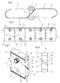
In der nachstehenden Beschreibung wird von einem Kragplattenelement gesprochen, welches bei bewehrten Baukonstruktionen am Übergang zwischen einer Deckenplatte und einer frei auskragenden Platte, z.B. einer Balkonplatte, eingesetzt wird. Die beschriebenen Maßnahmen sind aber in gleicher Weise auch für Fugenelemente einsetzbar, wo es in der Regel darum geht, zwischen Deckenabschnitten Wärme- und Schallisolationselemente einzubringen. Auch bei solchen Anwendungsfällen sind gegebenenfalls Zug- und/oder Druck-Bewehrungselemente sowie Querkraftstäbe einzusetzen.In the following description we speak of a cantilever plate element, which at reinforced building structures at the transition between a ceiling slab and a cantilevered one Plate, e.g. a balcony slab is used. However, the measures described are the same Can also be used for joint elements where it is usually a matter of between Ceiling sections bring heat and sound insulation elements. Even with such Use cases include tensile and / or pressure reinforcement elements as well Use shear bars.
Beim hier gezeigten Kragplattenelement ist ein Baukörper 1 vorgesehen, welcher aus einem
wärmeisolierenden Schaumstoff oder einem anderen wärmeisolierenden bzw. schalldämmenden
Material gefertigt ist. Der Baukörper 1 dient zur Aufnahme von Zug- und/oder Druck-Bewehrungselementen,
welche in Durchgangsöffnungen 2 eingeführt werden können. Bei der
gezeigten Konstruktion sind im Bereich der Durchgangsöffnungen Rohrkörper 3 eingesetzt, welche
beispielsweise aus Kunststoff bestehen. Durch diese Rohrkörper 3 und die von diesen gebildeten
Durchgangsöffnungen 2 können die über eine Deckenplatte und den daran anschließenden
auskragenden Plattenbereich hindurchgehenden Bewehrungselemente im Zug- und im Druckbereich
eingeschoben werden. Es ergeben sich dadurch keine Unterbrechungen in der Bewehrung. Ferner
sind im Kragplattenelement Querkraftstäbe 4 eingesetzt, welche einen schräg zur Horizontalen
verlaufenden Mittelabschnitt 5 und jeweils beidseitig des Baukörpers 1 gerade verlaufenden
Bereich 6, 7 aufweisen. Diese Bereiche 6, 7 verlaufen achsparallel zur Mittelachse 8, 9 der
Durchgangsöffnungen 2 bzw. der entsprechenden Rohrkörper 3.In the cantilever panel element shown here, a
Bei der hier gezeigten besonderen Ausführungsform eines Kragplattenelementes besteht der
Baukörper 1 aus mehreren Bauteilen 10, wobei diese Bauteile 10 im besonderen den Fig. 3 und 4
entnommen werden können.In the particular embodiment of a cantilever plate element shown here, the
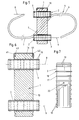
Zur Aufnahme der Rohrkörper 3 sind in jeweils annähernd der Mitte der Bauteile 10
Durchgangsöffnungen 2 vorhanden. Die Rohrkörper 3 weisen mehrere mit Abstand voneinander
angeordnete, umlaufende Rippen 17 auf, so daß die Rohrkörper 3 nicht vollflächig an der
Innenwandung der Durchgangsöffnungen 2 zur Anlage kommen. Dadurch ist ein relativ leichtes
Einschieben der Rohrkörper 3 in die Durchgangsöffnungen 2 möglich, wobei durch die Rippen 17
trotzdem eine entsprechende Halterung ohne zusätzliche Verklebung oder dergleichen erfolgen kann.
Um immer die gleiche Lage der eingeschobenen Rohrkörper 3 zu ermöglichen, wird eine
Anschlagrippe 18 vorgesehen, welche einen gegenüber den Rippen 17 größeren Durchmesser
aufweist. An den beidseitig den Baukörper 1 überragenden Enden der Rohrkörper 3 sind eine oder
mehrere zusätzliche Rippen 19 vorgesehen, welche zu einer entsprechend guten Verriegelung in dem
eingefüllten Beton dienen. Wenn außerdem gefordert ist, daß die in die Rohrkörper 3 eingesetzten
Zug- bzw. Druck-Bewehrungselemente gänzlich mit Beton umschlossen sind, dann bedarf es einer
Möglichkeit zum Entweichen überschüssiger Luftblasen im Bereich der Rohrkörper 3. Zu diesem
Zweck können beispielsweise eines oder mehrere Löcher 20 vorgesehen werden, über welche die
Luftblasen in den Ringraum zwischen jeweils zwei Rippen 17 entweichen können.To accommodate the
In der Fig. 2 sind die Querkraftstäbe zweimal voll und zweimal an ihrem Austrittspunkt aus dem
Baukörper 1 abgeschnitten dargestellt. Es ist hier eindeutig ersichtlich, daß in Längserstreckung des
Baukörpers 1 gesehen zwischen jeweils zwei in vertikaler Richtung übereinanderliegenden
Durchgangsöffnungen 2 bzw. entsprechenden Rohrkörpern 3 jeweils ein Querkraftstab 4 eingesetzt
ist.In Fig. 2, the shear bars are twice full and twice at their point of exit from the
Wie schon ausgeführt, ist der Baukörper 1 aus mehreren, in dessen Längsrichtung aufeinander
folgenden Bauteilen 10 gefertigt. Die aufeinander folgenden Bauteile 10 sind mit den seitlichen
Begrenzungsflächen 32, 33 einander zugewandt und schließen unmittelbar aneinander an. Die
Querkraftstäbe 4 werden dabei mit ihrem Mittelabschnitt 5 in von den einander zugewandten,
seitlichen Begrenzungsflächen 32, 33 eingeschlossene Durchgangsöffnungen eingesetzt, welche vor
dem Zusammenfügen der Bauteile als Nut 11 ausgebildet sind.As already stated, the
Die schließlich die Durchgangsöffnung bildende Nut 11 ist entsprechend dem Verlauf des
Mittelabschnittes 5 der Querkraftstäbe 4 ausgeführt. Wenn also - wie in der Regel vorgesehen - der
Mittelabschnitt 5 der Querkraftstäbe 4 schräg zur Horizontalen ausgerichtet ist, dann verläuft auch
die Nut 11 in einem korrespondierend dazu ausgebildeten Winkel. Die von den benachbarten
seitlichen Begrenzungsflächen 32, 33 der Bauteile 10 eingeschlossenen Durchgangsöffnungen 34
weisen in bezug auf deren Längserstreckung unterschiedliche Querschnittsabmessungen auf. Die
beiden nahe der Oberfläche des fertigen Baukörpers 1 liegenden Bereiche 35, 36 sind im Querschnitt
kleiner ausgeführt als der mittlere Bereich 37. Daher wird der in die Nut 11 einzulegende
Mittelabschnitt 5 des Querkraftstabes 4 nur in den Bereichen 35 und 36 besonders fixiert gehalten,
was für eine ordnungsgemäße Halterung ausreichend ist. Zum Eindrücken bzw. Einpressen des
Mittelabschnittes 5 in die Nut 11 sind dadurch geringere Kräfte erforderlich, und es ist daher sehr
einfach eine entsprechende Handmontage durchzuführen.The
Die Bereiche 35 und 36 sind dem Querschnitt des Mittelabschnittes 5 der Querkraftstäbe 4
entsprechend angepaßt bzw. so ausgebildet, daß der Mittelabschnitt 5 allein schon beim
Hineindrücken nach Art einer entsprechenden Passung form- und kraftschlüssig gehalten wird. In
diesem Zusammenhang ist es aber auch möglich, die Bereiche 35 und 36 der Nut 11 mit einem
quadratischen Querschnitt auszuführen, wobei dann eben die Abmessungen dieses im Querschnitt
quadratischen Bereiches der Nut dem Durchmesser der Querkraftstäbe entsprechend angepaßt sind.The
Aus der Zeichnung ist eine besonders vorteilhafte Konstruktionsvariante ersichtlich. Hier werden die
Durchgangsöffnungen 34 von der Nut 11 gebildet, welche komplett an einer seitlichen
Begrenzungsfläche 33 eines Bauteiles 10 ausgebildet ist. Die ebene seitliche Begrenzungsfläche 32
des nächstfolgenden Bauteiles 10 bildet also nur noch den Abschluß der Nut 11, um dadurch eine im
Querschnitt geschlossene Durchgangsöffnung 34 zu schaffen. Im Rahmen der Erfindung wäre es
auch denkbar, an beiden Begrenzungsflächen 32, 33 entsprechende Nuten vorzusehen, welche
diesfalls jeweils die Hälfte der Tiefe aufweisen und nach dem Zusammenfügen zweier Bauteile 10
den kompletten Querschnitt der Durchgangsöffnung 34 bilden. Die zuerst genannte konstruktive
Variante ist jedoch aus Montage- und Herstellungsgründen wesentlich einfacher, da einerseits die
Form zur Herstellung der Bauteile vereinfacht wird und andererseits die Querkraftstäbe bei der
Montage durch Einstecken in die einseitig vorgesehene Nut 11 festhaltend vormontiert werden
können. Es bedarf daher nurmehr eines Heranschiebens bzw. Aufdrückens des nächstfolgenden
Bauteiles, um den eingesetzten Querkraftstab zu fixieren. A particularly advantageous construction variant can be seen from the drawing. Here are the
Through
Gerade bei einer Ausführung, wo die Nut 11 nur an einer Begrenzungsfläche 33 ausgebildet ist,
erstreckt sich der Bereich 37 der Nut 11 mit dem größeren Querschnitt nur in Richtung des einen
Bauteiles 10, so daß an der gegenüberliegenden Seite eine über die ganze Länge wirkende
Abstützung durch den nächstfolgenden Bauteil erfolgt.Especially in an embodiment where the
Durch die besondere Ausbildung mit einer Nut zum Einlegen des Mittelabschnittes 5 des
Querkraftstabes 4 - ob diese Nut nun den halben oder den ganzen Querschnitt der
Durchgangsöffnung 34 bildet - besteht die Möglichkeit, eine Anpassung an die verschiedensten
Ausführungen von Querkraftstäben vorzunehmen. Somit können der Winkel des schrägen Verlaufes
der Nut 11, der Verlauf an sich und verschiedene Durchmesserparameter den Bauteilen 10 angepaßt
werden. Im Rahmen der Erfindung ist es auch denkbar, nicht nur eine Durchgangsöffnung 34 und
somit eine Nut 11 vorzusehen, sondern es wäre auch möglich, zwei oder mehrere
Durchgangsöffnungen 34 bzw. Nuten 11 anzuordnen, wobei die mehreren Durchgangsöffnungen 34
bzw. Nuten 11 auch in unterschiedlichen Winkellagen und mit unterschiedlichen Durchmessern oder
Durchmesserbereichen vorgesehen werden könnten. So wäre es auch denkbar, im Bereich der
seitlichen Begrenzungsflächen 32, 33 zusätzliche Aufnahmemöglichkeiten für Zug- und/oder Druck-Bewehrungselemente
zu schaffen, welche beispielsweise nach Art eines Steckeisen schon bei der
Montage des Kragplattenelementes miteingelegt werden könnten. Durch verschiedene
Gestaltungsmöglichkeiten an den seitlichen Begrenzungsflächen 32 und 33 wäre es auch möglich,
daß z.B. solche eingelegte Steckeisen und ein Querkraftstab in einer Ebene liegen oder aber
entsprechend versetzt zueinander angeordnet sind. Bei entsprechend tieferen Nuten 11 ist es dabei
auch möglich, daß an der gegenüberliegenden Begrenzungsfläche vorstehende Stege ausgebildet
werden, welche dann in die gegenüberliegenden Nuten am nächstfolgenden Bauteil 10 eingreifen,
um den von der Nut selbst gebildeten Querschnitt für die Durchgangsöffnung 34 zu verringern und
eine eventuell eingelegtes Bewehrungselement einzuklemmen.Due to the special design with a groove for inserting the
Zur einfachen Montage aufeinander folgender Bauteile 10 zur Bildung eines Baukörpers 1 und somit
eines fertigen Kragplatten- und/oder Fugenelementes können an den seitlichen Begrenzungsflächen
32, 33 zur gegenseitigen form- und/oder kraftschlüssigen Verbindung Kupplungselemente
ausgebildet werden. Beim gezeigten Ausführungsbeispiel sind Federn 12 sowie dazu
korrespondierende Nuten 13 vorgesehen. Um eine besonders gute Halterung zu erzielen, weisen die
Federn 12 und Nuten 13 Hinterschneidungen 38, 39 auf, welche z.B. nach Art einer
Schwalbenschwanzverbindung ausgeführt sind. Beim konkreten Beispiel - siehe insbesondere Fig. 2
bis 4 - ist an der einen seitlichen Begrenzungsfläche 33 eine in horizontaler Richtung, also quer zur
Frontseite 40 des Bauteiles 10 verlaufende Feder 12 mit schwalbenschwanzförmigen
Hinterschneidungen 38 und an der gegenüberliegenden seitlichen Begrenzungsfläche 32 eine im
Querschnitt korrespondierend ausgeführte Nut 13 mit entsprechenden Hinterschneidungen 39
ausgebildet. For simple assembly of
Die Bauteile 10 sind aus einem elastisch verformbaren Material gefertigt, beispielsweise aus einem
expandierten Schaumstoff oder einem anderen wärmedämmenden Material. Bauteile aus solchen
Materialien sind in gewissen Grenzen elastisch verformbar. Bei den hier vorgesehenen Bauteilen geht
die elastische Verformbarkeit gerade soweit, als die mit Hinterschneidungen 38, 39 versehenen
Kupplungselemente quer zum Verlauf dieser Federn 12 und Nuten 13 bzw. der Hinterschneidungen
38, 39 aufeinandersteckbar sind, wobei dann die durch die Hinterschneidungen 38, 39
gebildeten Nasen in ihre formschlüssige Stellung einrasten können.The
Im Rahmen der Erfindung ist es durchaus möglich, an jeder Begrenzungsfläche 32, 33 der
Bauteile 10 anstelle von nur einer Feder 12 und einer Nut 13 mehrere solcher Federn und Nuten
vorzusehen, wobei es auch möglich ist, an jeder Begrenzungsfläche 32, 33 sowohl Federn als auch
Nuten vorzusehen.Within the scope of the invention, it is entirely possible for the
In der vorstehenden Beschreibung wurde im wesentlichen von Kupplungselementen in Form von Federn und Nuten gesprochen. Im Rahmen der Erfindung ist es natürlich auch möglich, anstelle solcher Federn und Nuten Bolzen und Bohrungen bzw. Zapfen oder dergleichen auszubilden, wobei auch bei solchen Anordnungen entsprechende Hinterschneidungen zum gegenseitigen Kraft- und/oder Formschluß vorzusehen sind.In the above description, coupling elements in the form of Tongues and grooves spoken. Within the scope of the invention it is of course also possible instead such tongues and grooves to form bolts and bores or pins or the like, wherein corresponding undercuts for mutual force and / or Form locking must be provided.
Die Bauteile 10 können nahe ihrem oberen und/oder unteren Rand horizontal verlaufende
Nuten 14, 15 aufweisen. Es kann dann als oberer und/oder unterer Abschluß des Baukörpers 1 eine
im Querschnitt U-förmige Schiene 16 vorgesehen werden, welche an ihren beiden Schenkeln 41, 42
nach innen gerichtete Stege 43, 44 aufweist. Die Schiene 16 kann also einen entsprechend stabilen
oberen und/oder unteren Abschluß des Baukörpers 1 bilden, wobei die nach innen gerichteten
Stege 43, 44 in die Nuten 14 und/oder 15 an den Bauteilen 10 eingreifen. Im Rahmen der Erfindung
ist es möglich, die Schiene 16 zusätzlich zu den an den Begrenzungsflächen 32, 33 vorgesehenen
Kupplungsgliedern einzusetzen oder aber als alleinige Halterung zwischen den aufeinander folgenden
Bauteilen 10.The
Es ist im Rahmen der Erfindung ebenfalls möglich, sowohl beim Einsatz der durch Federn 12 und
Nuten 13 bzw. Zapfen und Bohrungen gebildeten Verbindungen als auch beim Einsatz einer
Schiene 16 zusätzlich Klebstoff anzuwenden, um die zusammengefügten Bauteile damit unlösbar
miteinander zu verbinden. In der Regel genügt die gegenseitige Steckverbindung aber vollständig aus,
um trotz des rauhen Baustellenbetriebes eine ordnungsgemäße Halterung zu gewährleisten. Es sind
auch durchaus verschiedene konstruktive Änderungen möglich, wobei jedoch stets die gegenseitige
form- und/oder kraftschlüssige Verbindung zwischen den einzelnen, den Baukörper bildenden
Bauteilen und die entsprechende Halterung zumindest der Querkraftstäbe zwischen den Bauteilen im
Vordergrund stehen müssen.It is also possible within the scope of the invention, both when using springs 12 and 12
Claims (12)
- A cantilever slab and/or joint element for reinforced structures, comprising a structural member designed to accommodate tension and/or compression reinforcing elements, and also transverse force rods inserted or able to be inserted in this structural member, wherein the transverse force rods have a central portion engaging in the structural member and portions projecting on either side of the structural member, characterised in that the structural member (1) comprises a plurality of structural parts (10) which succeed one another in the longitudinal direction, which adjoin one another with their mutually facing lateral boundary surfaces (32,33) and which can be joined together in a form-locking and/or force-locking manner so as to form the structural member (1), and in that the transverse force rods (4) can be inserted or are inserted with their central portion (5) in through-openings (34) which are enclosed by the mutually facing lateral boundary surfaces (32,33) and which are formed slot-like before the joining together of the structural parts (10).
- A cantilever slab and/or joint element according to Claim 1, characterised in that for accommodating the central portion (5) of the transverse force rods (4) in conformity with a course of said portion corresponding thereto optionally aligned obliquely to the horizontal the through-openings (34) extend obliquely to the horizontal.
- A cantilever slab and/or joint element according to Claim 1 or 2, characterised in that the through-openings (34) enclosed by the adjacent lateral boundary surfaces (32,33) of the structural parts (10) are of different cross-sectional dimensions in relation to the longitudinal extension thereof.
- A cantilever slab and/or joint element according to Claim 1, 2 or 3, characterised in that the two regions (35,36) of the through-openings (34) situated near the surface of the finished structural member (1) are smaller in cross-section than the central region (37).
- A cantilever slab and/or joint element according to Claim 4, characterised in that the regions (35,36) of the through-openings (34) are of smaller cross-section corresponding to the cross-section of the central portion (5) of the transverse force rods (4) or at least one portion (35,36) of approximately square cross-section is provided adapted to the diameter of the transverse force rods (4).
- A cantilever slab and/or joint element according to any one Claims 1 to 5, characterised in that the through-openings (34) are enclosed by a slot (11) disposed on a lateral boundary surface (33) of a structural part and the flat lateral boundary surface (32) of the succeeding structural part (10).
- A cantilever slab and/or joint element according to any one Claims 4 to 6, characterised in that the region (37) of the through-opening (34) having the larger cross-section, viewed in the longitudinal extension of the structural member (1), extends only towards the slot (11) formed in the lateral boundary surface (33).
- A cantilever slab and/or joint element according to Claim 1, characterised in that coupling elements, for example webs or tongues (12), grooves (13), pegs or bores, are formed on the lateral boundary surfaces (32,33) of the structural parts (10) for mutual form-locking and/or force-locking connection.
- A cantilever slab and/or joint element according to Claim 8, characterised in that the coupling elements are provided with undercuts (38,39), for example in the manner of a dovetail joint.
- A cantilever slab and/or joint element according to Claims 1 and/or 7 to 9, characterised in that on one lateral boundary surface (33) of each structural part (10) a tongue (12) having dovetail-shaped undercuts (38) is formed extending in a horizontal direction, i.e. transversely to the front side (40) of each structural part (10), and a groove (13) of corresponding cross-section is formed on the opposite lateral boundary surface (32).
- A cantilever slab and/or joint element according to Claims 9 and 10, characterised in that the structural parts (10) are produced from a material which is elastically deformable to the extent that the coupling elements provided with undercuts (38,39) can be fitted on to one another transversely to the course of the undercuts (38,39) and engage in their form-locking position.
- A cantilever slab and/or joint element according to Claim 1, characterised in that the structural parts (10) have horizontally extending grooves (14,15) near their upper and/or lower edge, wherein a rail (16) of U-shaped cross-section is provided as the upper and/or lower termination of the structural member (1), which rail engages with inwardly directed webs (43,44) formed on its two arms (41,42) into the grooves (14,15) in the structural parts (10).
Applications Claiming Priority (2)
| Application Number | Priority Date | Filing Date | Title |
|---|---|---|---|
| DE19519614A DE19519614C2 (en) | 1995-05-29 | 1995-05-29 | Cantilever and / or joint element for reinforced building constructions |
| DE19519614 | 1995-05-29 |
Publications (2)
| Publication Number | Publication Date |
|---|---|
| EP0745732A1 EP0745732A1 (en) | 1996-12-04 |
| EP0745732B1 true EP0745732B1 (en) | 1999-11-03 |
Family
ID=7763107
Family Applications (1)
| Application Number | Title | Priority Date | Filing Date |
|---|---|---|---|
| EP96108395A Expired - Lifetime EP0745732B1 (en) | 1995-05-29 | 1996-05-28 | Cantilever balcony plate element preventing cold bridging |
Country Status (3)
| Country | Link |
|---|---|
| EP (1) | EP0745732B1 (en) |
| AT (1) | ATE186355T1 (en) |
| DE (2) | DE19519614C2 (en) |
Families Citing this family (4)
| Publication number | Priority date | Publication date | Assignee | Title |
|---|---|---|---|---|
| FR2750045B1 (en) | 1996-06-19 | 1998-07-24 | Oreal | USE OF COLLOIDAL SILICIC ACID IN A NAIL VARNISH COMPOSITION |
| DE19722051A1 (en) * | 1997-05-27 | 1998-12-03 | Schoeck Bauteile Gmbh | Modular building component system for heat insulation |
| DE19722050B4 (en) * | 1997-05-27 | 2006-02-16 | Schöck Bauteile GmbH | Component for thermal insulation |
| GB2563085A (en) * | 2017-06-03 | 2018-12-05 | Insula Ltd | Connection and alignment of building elements |
Family Cites Families (6)
| Publication number | Priority date | Publication date | Assignee | Title |
|---|---|---|---|---|
| DE3302719C1 (en) * | 1983-01-27 | 1984-08-23 | Eberhard Ing. Schöck (grad.), 7570 Baden-Baden | Component for heat insulation in buildings |
| DE8530376U1 (en) * | 1985-10-26 | 1986-04-24 | Hifra GmbH, Olten | Rebar connection |
| DE3739967A1 (en) * | 1987-11-25 | 1989-06-08 | Meisinger Kg M | STEEL BEAM FOR A CONCRETE PLATE |
| AT395622B (en) * | 1989-06-05 | 1993-02-25 | Josef Fuhs | REINFORCEMENT FOR CONNECTING A BALCONY PLATE |
| DE9409324U1 (en) * | 1994-06-09 | 1995-10-12 | Dausend Hans Werner | Cantilever panel connection element with a heat-insulating body |
| DE9417777U1 (en) * | 1994-11-05 | 1995-01-05 | Dausend Hans Werner | Cantilever panel connection element |
-
1995
- 1995-05-29 DE DE19519614A patent/DE19519614C2/en not_active Expired - Fee Related
-
1996
- 1996-05-28 EP EP96108395A patent/EP0745732B1/en not_active Expired - Lifetime
- 1996-05-28 DE DE59603533T patent/DE59603533D1/en not_active Expired - Fee Related
- 1996-05-28 AT AT96108395T patent/ATE186355T1/en not_active IP Right Cessation
Also Published As
| Publication number | Publication date |
|---|---|
| EP0745732A1 (en) | 1996-12-04 |
| DE59603533D1 (en) | 1999-12-09 |
| DE19519614C2 (en) | 2000-03-16 |
| ATE186355T1 (en) | 1999-11-15 |
| DE19519614A1 (en) | 1996-12-05 |
Similar Documents
| Publication | Publication Date | Title |
|---|---|---|
| EP0641901B1 (en) | Mounting or construction system for a wooden house | |
| EP0040815B1 (en) | Site-assembled composite beam | |
| EP0117897B1 (en) | Building element for thermal insulation of buildings | |
| EP4036338B1 (en) | Device for the subsequent thermal insulation, force-transmitting connection of a second load-bearing building element to a first load-bearing construction element and construction with such a device | |
| WO2010145642A2 (en) | Permanent formwork | |
| EP0745732B1 (en) | Cantilever balcony plate element preventing cold bridging | |
| DE102006032444A1 (en) | Construction element used as heat insulation between two components to be covered with concrete comprises a connecting element traversing and fixing an insulating body relative to a compression and/or transverse force element and tie rods | |
| EP0751266B1 (en) | Block for shutterings | |
| EP0442130B1 (en) | Prefab unit as joint and/or expansion unit and/or cantilever plate element for reinforced cement-bound building constructions | |
| AT402084B (en) | LOST FORMWORK ELEMENT | |
| EP0831183B1 (en) | Construction element for heat insulation | |
| EP0745733A1 (en) | Cantilever plate element and/or seal element for reinforced building constructions | |
| EP0745734B1 (en) | Cantilever plate element and/or seal element for reinforced building constructions | |
| EP0959188B1 (en) | Cantilevered slab and/or joint element for reinforced concrete structures | |
| DE19814452A1 (en) | Connection between loadbearing and cantilevered components used for e.g. balconies of buildings | |
| EP0353560A1 (en) | Spacer for concrete reinforcements | |
| EP1002167A1 (en) | Spacer | |
| EP1600572B1 (en) | Support for waterstop and method of producing concrete sections | |
| EP0167106A2 (en) | Hollow plug for railway construction | |
| DE102007006401B4 (en) | Clean room wall | |
| CH683443A5 (en) | Blockhouse-type building. | |
| DE3926359C2 (en) | Housing for a roller shutter | |
| WO2023021118A1 (en) | Spacer for connecting an insulating plate to a wall panel | |
| DE4327115A1 (en) | Spacer for panel elements of a wall/ceiling system | |
| DE102021125300A1 (en) | Spacer for connecting an insulation panel to a wall panel |
Legal Events
| Date | Code | Title | Description |
|---|---|---|---|
| PUAI | Public reference made under article 153(3) epc to a published international application that has entered the european phase |
Free format text: ORIGINAL CODE: 0009012 |
|
| AK | Designated contracting states |
Kind code of ref document: A1 Designated state(s): AT CH DE FI FR LI |
|
| 17P | Request for examination filed |
Effective date: 19970604 |
|
| GRAG | Despatch of communication of intention to grant |
Free format text: ORIGINAL CODE: EPIDOS AGRA |
|
| GRAG | Despatch of communication of intention to grant |
Free format text: ORIGINAL CODE: EPIDOS AGRA |
|
| GRAH | Despatch of communication of intention to grant a patent |
Free format text: ORIGINAL CODE: EPIDOS IGRA |
|
| 17Q | First examination report despatched |
Effective date: 19990415 |
|
| GRAH | Despatch of communication of intention to grant a patent |
Free format text: ORIGINAL CODE: EPIDOS IGRA |
|
| GRAA | (expected) grant |
Free format text: ORIGINAL CODE: 0009210 |
|
| AK | Designated contracting states |
Kind code of ref document: B1 Designated state(s): AT CH DE FI FR LI |
|
| PG25 | Lapsed in a contracting state [announced via postgrant information from national office to epo] |
Ref country code: FR Free format text: LAPSE BECAUSE OF FAILURE TO SUBMIT A TRANSLATION OF THE DESCRIPTION OR TO PAY THE FEE WITHIN THE PRESCRIBED TIME-LIMIT Effective date: 19991103 Ref country code: FI Free format text: LAPSE BECAUSE OF NON-PAYMENT OF DUE FEES Effective date: 19991103 |
|
| REF | Corresponds to: |
Ref document number: 186355 Country of ref document: AT Date of ref document: 19991115 Kind code of ref document: T |
|
| REG | Reference to a national code |
Ref country code: CH Ref legal event code: EP |
|
| REF | Corresponds to: |
Ref document number: 59603533 Country of ref document: DE Date of ref document: 19991209 |
|
| EN | Fr: translation not filed | ||
| PGFP | Annual fee paid to national office [announced via postgrant information from national office to epo] |
Ref country code: CH Payment date: 20000403 Year of fee payment: 5 |
|
| PGFP | Annual fee paid to national office [announced via postgrant information from national office to epo] |
Ref country code: AT Payment date: 20000410 Year of fee payment: 5 |
|
| PLBE | No opposition filed within time limit |
Free format text: ORIGINAL CODE: 0009261 |
|
| STAA | Information on the status of an ep patent application or granted ep patent |
Free format text: STATUS: NO OPPOSITION FILED WITHIN TIME LIMIT |
|
| 26N | No opposition filed | ||
| PG25 | Lapsed in a contracting state [announced via postgrant information from national office to epo] |
Ref country code: DE Free format text: LAPSE BECAUSE OF NON-PAYMENT OF DUE FEES Effective date: 20010301 |
|
| PG25 | Lapsed in a contracting state [announced via postgrant information from national office to epo] |
Ref country code: AT Free format text: LAPSE BECAUSE OF NON-PAYMENT OF DUE FEES Effective date: 20010528 |
|
| PG25 | Lapsed in a contracting state [announced via postgrant information from national office to epo] |
Ref country code: LI Free format text: LAPSE BECAUSE OF NON-PAYMENT OF DUE FEES Effective date: 20010627 Ref country code: CH Free format text: LAPSE BECAUSE OF NON-PAYMENT OF DUE FEES Effective date: 20010627 |
|
| REG | Reference to a national code |
Ref country code: CH Ref legal event code: PL |