EP0959188B1 - Cantilevered slab and/or joint element for reinforced concrete structures - Google Patents
Cantilevered slab and/or joint element for reinforced concrete structures Download PDFInfo
- Publication number
- EP0959188B1 EP0959188B1 EP99108900A EP99108900A EP0959188B1 EP 0959188 B1 EP0959188 B1 EP 0959188B1 EP 99108900 A EP99108900 A EP 99108900A EP 99108900 A EP99108900 A EP 99108900A EP 0959188 B1 EP0959188 B1 EP 0959188B1
- Authority
- EP
- European Patent Office
- Prior art keywords
- ribs
- tubular body
- tubular member
- joint element
- element according
- Prior art date
- Legal status (The legal status is an assumption and is not a legal conclusion. Google has not performed a legal analysis and makes no representation as to the accuracy of the status listed.)
- Expired - Lifetime
Links
Images
Classifications
-
- E—FIXED CONSTRUCTIONS
- E04—BUILDING
- E04B—GENERAL BUILDING CONSTRUCTIONS; WALLS, e.g. PARTITIONS; ROOFS; FLOORS; CEILINGS; INSULATION OR OTHER PROTECTION OF BUILDINGS
- E04B1/00—Constructions in general; Structures which are not restricted either to walls, e.g. partitions, or floors or ceilings or roofs
- E04B1/003—Balconies; Decks
- E04B1/0038—Anchoring devices specially adapted therefor with means for preventing cold bridging
Landscapes
- Engineering & Computer Science (AREA)
- Architecture (AREA)
- Physics & Mathematics (AREA)
- Electromagnetism (AREA)
- Civil Engineering (AREA)
- Structural Engineering (AREA)
- Joining Of Building Structures In Genera (AREA)
- Rod-Shaped Construction Members (AREA)
Abstract
Description
Die Erfindung betrifft ein Kragplatten- und/oder Fugenelement für bewehrte Baukonstruktionen, mit einem zur Aufnahme von Zug- und/oder Druckbewehrungselementen und gegebenenfalls Querkraftstäben ausgebildeten, ein- oder mehrteiligen Baukörper, wobei zur Aufnahme der Zug - und/oder Druckbewehrungselemente im Baukörper annähernd quer zu einer vertikalen Längsmittelebene desselben verlaufende Durchgangsöffnungen vorgesehen sind, und mit einem Rohrkörper, wobei dieser in die Durchgansöffnung eingesetzt oder einsetzbar ist, welcher an seiner Außenoberfläche mehrere, zumindest annähernd in Umfangsrichtung verlaufende Rippen aufweist, über welche der Rohrkörper kraft- und/oder formschlüssig an der Innenwandung der Durchgangsöffnung im Baukörper abstützbar ist.The invention relates to a cantilever and / or joint element for reinforced building structures, with one for receiving tension and / or compression reinforcement elements and, if necessary Shear force rods designed, one-part or multi-part structure, with the tensile - and / or pressure reinforcement elements in the structure approximately transversely to a vertical Through openings extending therealongplane are provided, and with a tubular body, this in the through opening is used or can be used, which on its outer surface several, at least has approximately circumferential ribs over which the tubular body and / or can be positively supported on the inner wall of the through opening in the building.
Gerade Kragplatten, aber auch andere im Bereich einer Gebäudeumfassung ins Freie vorstehende Baukörper bilden erhebliche Wärmebrücken zwischen der Innen- und der Außentemperatur. Im Bereich solcher Wärmebrücken ist man in den vergangenen Jahren immer mehr dazu übergegangen, Isolationselemente einzusetzen, um die vorstehenden Baukörper von den innenliegenden Baukörpern in gewisser Weise thermisch zu trennen. Damit können zwar die Überlegungen bezüglich des Wärme- bzw. des Schallüberganges gelöst werden, doch bedarf es bei solchen Deckenkonstruktionen der Schaffung einer statischen Einheit zwischen einer Deckenkonstruktion und einer auskragenden Platte. In der Regel werden an den gegenseitigen Anschlußseiten Steckeisen für die obere und die untere Bewehrung in die Deckenplatte einbetoniert, welche hinreichend vorstehen, um in die auskragende Platte, z.B. in eine Balkonplatte, eingreifen zu können.Cantilever panels in particular, but also others protruding outdoors in the area of a building enclosure Buildings form significant thermal bridges between the inside and outside temperature. in the The area of such thermal bridges has become more and more popular in recent years, Use insulation elements to separate the protruding structures from the internal structures to sort of thermally separate. With this, the considerations regarding the heat or the sound transition can be solved, but such ceiling constructions require the Creation of a static unit between a ceiling construction and a cantilever Plate. As a rule, there are pegs for the upper and the opposite ends the lower reinforcement is concreted into the ceiling slab, which protrude sufficiently to enter the cantilever plate, e.g. to intervene in a balcony slab.
Es ist bereits ein Bauelement zur Wärmedämmung bei Gebäuden bekannt geworden (EP-A1-0 568 813), bei welchem Bewehrungsstäbe, die sich quer zum Isolierkörper durch diesen hindurcherstrecken und beidseitig vorstehen, in ein Rohr eingesetzt werden, welches nach innen ragende Vorsprünge aufweist, um dadurch zu erreichen, daß der Bewehrungsstab inetwa in der Mitte des Rohres verbleibt und aus Korrosionsgründen vom Beton oder von der Betonmilch ganz umschlossen wird. Zu diesem Zweck weist das Rohr in der Rohrwandung eine Vielzahl von Öffnungen auf, um den Eintritt von Beton oder Betonmilch in den Spalt zu gestatten. Zur Befestigung dieses Rohrkörpers in dem Isolierkörper sind relativ hohe axial verlaufende Erhebungen vorgesehen, welche sich beim Hineinschieben in einem vorbereiteten Durchgangsloch eingraben sollen. Wenn die Rippen oder Erhebungen jedoch ein entsprechendes Ausmaß annehmen, ergeben sich kaum lösbare Probleme, denn gerade dann, wenn der Baukörper aus einem Schaumstoff gefertigt wird, können keine übermäßigen Kräfte aufgenommen werden, ohne daß die Begrenzung des Durchgangsloches zumindest im rückwärtigen Bereich ausbricht. A component for thermal insulation in buildings has already become known (EP-A1-0 568 813), in which reinforcing bars that run transversely to the insulating body through this extend through and protrude on both sides, inserted into a tube that faces inwards projecting projections to thereby achieve that the reinforcing bar approximately in the middle remains of the pipe and, for reasons of corrosion, of the concrete or of the concrete milk entirely is enclosed. For this purpose, the tube in the tube wall has a variety of Openings to allow the entry of concrete or milk into the gap. For fixing this tubular body in the insulating body, relatively high axially extending elevations are provided, which should dig into a prepared through hole when pushed in. If the Ribs or elevations, however, assume a corresponding extent, there are hardly any detachable Problems, because especially when the building structure is made of foam no excessive forces can be absorbed without limiting the through hole breaks out at least in the rear area.
Ebenfalls ist auch bereits ein als Fugen- und/oder Dilatations- und/oder Kragplattenelement einsetzbarer Bauteil bekannt geworden (EP-B1-0 442 130), in welchem Öffnungen zur Aufnahme von Rohrstücken vorgesehen sind. Durch diese Rohrstücke hindurch können die Bewehrungselemente der Betonkonstruktion hindurchgeführt werden, so daß eine durchgehende Bewehrung gewährleistet ist. Bei dieser Ausführung wird ein an der Außenoberfläche glattes Rohr eingesetzt, welches leicht in eine vorbereitete Durchgangsöffnung eingeführt werden kann.There is also already a joint and / or dilation and / or cantilever element usable component known (EP-B1-0 442 130), in which openings for receiving of pipe sections are provided. The reinforcement elements can pass through these pipe sections the concrete structure are passed through, so that a continuous reinforcement is guaranteed. This version uses a tube that is smooth on the outer surface, which can be easily inserted into a prepared through opening.
Weiter ist ein Kragplatten- und/oder Fugenelement für bewehrte Baukonstruktionen bekannt geworden (EP-A1-0 745 734), bei welchem quer zur vertikalen Längsmittelebene des dieses Kragplattenelement bildenden Baukörpers verlaufende Rohrkörper eingesetzt sind. Die Rohrkörper weisen an ihrer Außenoberfläche mehrere in Umfangsrichtung verlaufende Rippen auf, über welche der Rohrkörper an der Innenwandung einer zylindrischen Durchgangsöffnung im Baukörper abstützbar ist. Zur Verhinderung einer Blasenbildung beim Ausgießen mit Beton wird u.a. vorgeschlagen, in der Wandung des Rohrkörpers mehrere Bohrungen vorzusehen, durch welche die Luftblasen entweichen können.Furthermore, a cantilever panel and / or joint element for reinforced building structures is known become (EP-A1-0 745 734), in which transverse to the vertical longitudinal median plane of this Cantilever element forming tubular body are used. The tubular body have on their outer surface a plurality of ribs running in the circumferential direction, over which the tubular body can be supported on the inner wall of a cylindrical through opening in the structure is. To prevent bubbles from forming when pouring concrete, suggested in the Wall of the tubular body to provide several holes through which the air bubbles escape can.
Bei einer anderen bekannten Ausgestaltung eines dämmenden Übergangselementes, insbesondere für
Kragplattenanschlüsse (DE-U-89 05 521), wird im Bereich des Durchlasses für durchgehende
Bewehrungen ein mit beiden Enden über den Baukörper vorstehendes Rohr eingesetzt, wobei die
Höhe des Durchlassquerschnittes dieses Rohres größer ist als die Breite des Durchlassquerschnittes.
Das Rohr ist in seinem oberen Scheitelbereich mit einem Luftauslassweg versehen, der als nutartige
Fortsetzung des Rohr-Durchlassquerschnitts ausgebildet ist und von der Längsmitte des Rohrs zu
dessen beiden Enden hin ansteigt. Durch diese insgesamt nach zwei Seiten hin erfolgende
Erweiterung des Rohres ist die Montage desselben im Baukörper schwierig, da ein solches Rohr nicht
einfach in eine Durchgangsöffnung eingeschoben werden kann. Daher bedarf es eines ganz
besonderen konstruktiven Aufwandes beim Aufbau des Baukörpers. Die DE-U-8 905 521 offenbart
ein Kragplatten- und/oder Fugenelement, das die Merkmale des Oberbegriffes des
Anspruchs 1 aufweist.In another known embodiment of an insulating transition element, in particular for
Cantilever panel connections (DE-U-89 05 521), is in the area of the passage for continuous
Reinforcements used with both ends projecting over the pipe, the
The height of the passage cross section of this tube is greater than the width of the passage cross section.
The tube is provided in its upper apex area with an air outlet path which is groove-like
Continuation of the tube passage cross section is formed and from the longitudinal center of the tube to
the two ends of which rise. Through this, taking place on two sides
Extension of the pipe is difficult to assemble the same in the structure, since such a pipe is not
can simply be inserted into a through opening. So one thing is needed
special design effort when building the structure. DE-U-8 905 521 discloses
a cantilever and / or joint element, which has the features of the preamble of
Die vorliegende Erfindung hat sich zur Aufgabe gestellt, einen Rohrkörper für Kragplatten- und/oder Fugenelemente zu schaffen, mit welchem die Bildung von Luftblasen beim Ausgießen mit Beton verhindert werden kann, welcher jedoch trotzdem in wirtschaftlicher Weise herstellbar ist und einfach in einer vorbereiteten Durchgangsöffnung im Baukörper montiert werden kann.The present invention has for its object a tubular body for cantilever and / or To create joint elements with which the formation of air bubbles when pouring with concrete can be prevented, but which is nevertheless economically producible and can be easily installed in a prepared through opening in the building.
Erfindungsgemäß gelingt dies durch die im Patentanspruch 1 angegebenen Merkmale.According to the invention this is achieved by the features specified in
Durch die vorliegende Erfindung wird also eine Kombination in konstruktiver Hinsicht vorgeschlagen, indem die vorteilhafte Ausbildung einer konischen Erweiterung des Rohrkörpers zu wenigstens einem Ende desselben hin vorgesehen wird, um beim Ausgießvorgang den Abtransport von Luftblasen sicher zu bewerkstelligen, und trotzdem die Möglichkeit geschaffen wird, einen solchen Rohrkörper in eine vorbereitete Durchgangsöffnung einschieben zu können. Die Durchgangsöffnung ist dem Querschnitt des Rohrkörpers in dessen Außenbereich angepaßt, kann aber mit durchgehend gleichen Abmessungen ausgeführt werden. Speziell hier wirkt sich die erfindungsgemäße Ausgestaltung vorteilhaft aus, da trotz der konischen Erweiterung des Rohrkörpers von den vorstehenden Rippen ein gemeinsamer Hüllzylinder gebildet wird, so daß der Rohrkörper in dessen Achsrichtung in eine zylindrische Durchgangsöffnung eingeschoben werden kann.The present invention therefore proposes a combination in terms of construction, by the advantageous design of a conical extension of the tubular body to at least one End of the same is provided in order to remove air bubbles during the pouring process to accomplish safely, and yet the possibility is created of such a tubular body to be able to slide into a prepared through opening. The through opening is that Cross-section of the tubular body adapted in the outer area, but can be the same throughout Dimensions are executed. The configuration according to the invention has an effect here in particular advantageous because despite the conical expansion of the tubular body from the protruding ribs a common envelope cylinder is formed so that the tubular body in its axial direction in a cylindrical through opening can be inserted.
Trotz dieser sehr wesentlichen erfinderischen Maßnahmen ist eine wirtschaftliche Herstellungsmöglichkeit für solche Rohrkörper gewährleistet. Da die in Umfangsrichtung verlaufenden Rippen dafür sorgen, daß die Außenoberfläche des Rohrkörpers und die Innenwandung der Durchgangsöffnung nicht vollflächig aneinander anliegen, kann der Rohrkörper relativ einfach und ohne Ausbrechen von Abschnitten des Baukörpers in die Durchgangsöffnung hineingeschoben werden. Weil aber die in Umfangsrichtung verlaufenden Rippen sozusagen quer zur Einschubrichtung liegen, bewirken diese eine optimale Hemmung gegen ein Zurückziehen. Daher ist es nur mit besonderer Krafteinwirkung möglich, den Rohrkörper nach dem Einsetzen wieder aus der Durchgangsöffnung herauszuziehen.Despite these very essential inventive measures, it is an economical manufacturing option guaranteed for such tubular body. Because the circumferential ribs ensure that the outer surface of the tubular body and the inner wall of the through opening do not rest against each other over the entire surface, the tubular body can be relatively simple and without Breaking out sections of the building structure are pushed into the through opening. But because the ribs running in the circumferential direction are, so to speak, transverse to the direction of insertion, cause an optimal inhibition against withdrawal. Therefore, it is only with special Force can be exerted, the tube body out of the through opening after insertion pull it out.
Gemäß einer besonderen Ausgestaltung ist vorgesehen, daß der Rohrkörper nach beiden Enden hin konisch erweitert ausgebildet ist. Die ist deshalb vorteilhaft, weil dadurch die Wege für ein Entweichen von Luftblasen beim Ausgießen mit Beton wesentlich verkürzt werden können. Die Luftblasen entfernen sich nach beiden Richtungen hin aus dem Rohrkörper, so daß die Gewähr gegeben ist, daß nach dem Füllen mit Beton keine Luftblasen mehr innerhalb des Rohrkörpers vorhanden sind. Gerade in diesem Zusammenhang ist es vorteilhaft, wenn der Rohrkörper aus zwei annähernd von dessen Mitte bezogen auf dessen Längserstreckung ausgehenden kegelstumpfförmigen Hülsenabschnitten gebildet ist.According to a special embodiment it is provided that the tubular body towards both ends is flared. This is advantageous because it opens the way for one Escaping air bubbles when pouring concrete can be significantly reduced. The Air bubbles are removed from the tube body in both directions, so that the guarantee is given that after filling with concrete no more air bubbles inside the tube body available. In this context, it is advantageous if the tubular body consists of two approximately starting from its center with respect to its longitudinal extent frustoconical sleeve sections is formed.
Eine besonders zweckmäßige Ausführung wird darin gesehen, daß der Rohrkörper über seine ganze Länge eine annähernd gleichbleibende Wandstärke besitzt, wobei die in Achsrichtung aufeinander folgenden Rippen verschiedene radiale Abmessungen aufweisen. Es wird dadurch nur sehr wenig Material für den Rohrkörper benötigt, wobei es außerdem keine ganz besonderen Materialanhäufungen gibt. Dies ist auch für die Fertigung des Rohrkörpers selbst von besonderem Vorteil.A particularly useful design is seen in the fact that the tubular body over its entire Length has an approximately constant wall thickness, with each other in the axial direction following ribs have different radial dimensions. As a result, it becomes very little Material needed for the tubular body, and there are also no very special material accumulations gives. This is also of particular advantage for the manufacture of the tubular body itself.
Weiter wird vorgeschlagen, daß an der Außenoberfläche des Rohrkörpers mehrere mit Abstand parallel zueinander verlaufende Rippen vorgesehen sind, welche unterschiedlich große radiale Abmessungen aufweisen, so daß deren Außenbegrenzungen einen gemeinsamen Hüllzylinder oder ein gemeinsames Hüllprisma oder einen gemeinsamen Hüllkegel bilden. Um trotz des im wesentlichen von kegelstumpfförmigen Hülsenabschnitten gebildeten Rohrkörpers eine Außenbegrenzung mit einem gemeinsamen Hüllzylinder zu schaffen, werden die Rippen an den unterschiedlichen Stellen in axialer Richtung bezogen auf die Länge des Rohrkörpers gesehen einfach verschieden hoch ausgebildet. Demgemäß bilden die Außenbegrenzungen der Rippen wieder den gemeinsamen Hüllzylinder, um den Rohrkörper in einfacher Weise in eine vorbereitete Durchgangsöffnung einschieben zu können. Durch diese Ausgestaltung sind trotz der Möglichkeit des axialen Einschiebens des Rohrkörpers in eine Durchgangsöffnung eine exakte Zentrierung und Abstützung des Rohrkörpers in der Durchgangsöffnung möglich.It is further proposed that several at a distance on the outer surface of the tubular body parallel ribs are provided, which have different radial sizes Have dimensions so that the outer limits of a common envelope cylinder or form a common envelope prism or a common envelope cone. To despite the essentially tubular body formed by frustoconical sleeve sections with an outer boundary To create a common envelope cylinder, the ribs are in at different locations axial direction in relation to the length of the tubular body is simply different in height educated. Accordingly, the outer boundaries of the ribs form the common one again Envelope cylinder to the tubular body in a simple manner in a prepared through opening to be able to insert. This configuration, despite the possibility of axial Pushing the tubular body into a through opening, exact centering and support of the tubular body in the through opening possible.
Gemäß einer anderen Ausführungsvariante verlaufen die Rippen schraubenlinienförmig an der Oberfläche des Rohrkörpers und weisen bezogen auf deren Länge unterschiedliche radiale Höhe auf. Auch mit einer solchen Anordnung wird erreicht, daß die Außenbegrenzung der schraubenlinienförmig verlaufenden Rippen einen gemeinsamen Hüllzylinder bilden. Die Rückhaltekraft für den einmal eingeschobenen Rohrkörper wird durch die schraubenlinienförmig verlaufenden Rippen noch weiter erhöht.According to another embodiment variant, the ribs run helically on the Surface of the tubular body and have different radial heights based on their length. Even with such an arrangement it is achieved that the outer boundary of the helical extending ribs form a common envelope cylinder. The retention force for the Once inserted, the tubular body is still through the helical ribs further increased.
Um eine stets gleichbleibende und problemlose Montage des Rohrkörpers zu ermöglichen, wird vorgeschlagen, daß zur Bildung eines Anschlagflansches an einem Ende oder mit Abstand vom einen Ende des Rohrkörpers eine Rippe mit gegenüber den anderen Rippen größerem Durchmesser vorgesehen ist. Der Rohrkörper muß diesfalls zwar immer von derselben Seite her in die Durchgangsöffnung im Baukörper eingeschoben werden, jedoch ist zur Bestimmung der Eindringtiefe stets ein Anschlagflansch vorhanden.In order to enable a constant and problem-free assembly of the tubular body, proposed that to form a stop flange at one end or at a distance from one At the end of the tubular body a rib with a larger diameter than the other ribs is provided. In this case, the tubular body must always be in the same side Through opening in the building can be inserted, however, to determine the depth of penetration a stop flange is always available.
Weitere erfindungsgemäße Merkmale und besondere Vorteile werden in der nachstehenden Beschreibung anhand der Zeichnung noch näher erläutert. Es zeigen:
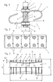
- Fig. 1
- einen Vertikalschnitt durch ein Kragplattenelement im Bereich der zur Aufnahme von Zug- und/oder Druckbewehrungselementen ausgebildeten Durchgangsöffnungen;
- Fig. 2
- eine Frontansicht eines aus mehreren Einzelteilen zusammengesetzten Baukörpers für ein Kragplattenelement;
- Fig. 3
- ein teilweise aufgeschnittenes Rohrstück, welches in die Durchgangsöffnungen im Kragplattenelement eingesetzt ist.
- Fig. 1
- a vertical section through a cantilever plate element in the region of the through openings designed to accommodate tension and / or compression reinforcement elements;
- Fig. 2
- a front view of a structure composed of several individual parts for a cantilever panel element;
- Fig. 3
- a partially cut piece of pipe, which is inserted into the through openings in the cantilever plate element.
In der nachstehenden Beschreibung wird von einem Kragplattenelement gesprochen, welches bei bewehrten Baukonstruktionen am Übergang zwischen einer Deckenplatte und einer frei auskragenden Platte, z.B. einer Balkonplatte, eingesetzt wird. Die beschriebenen Maßnahmen sind aber in gleicher Weise auch für Fugenelemente einsetzbar, wo es in der Regel darum geht, zwischen Deckenabschnitten Wärme- und Schallisolationselemente einzubringen. Auch bei solchen Anwendungsfällen sind gegebenenfalls Zug- und/oder Druckbewehrungselemente sowie eventuell Querkraftstäbe einzusetzen. In the following description we speak of a cantilever plate element, which at reinforced building structures at the transition between a ceiling tile and a cantilever Plate, e.g. a balcony slab is used. However, the measures described are the same Can also be used for joint elements, where it is usually a question of between ceiling sections Introduce heat and sound insulation elements. Even in such applications are, if necessary, tensile and / or compression reinforcement elements and possibly shear bars use.
Beim hier gezeigten Kragplattenelement ist ein Baukörper 1 vorgesehen, welcher aus einem
wärmeisolierenden Schaumstoff oder einem anderen wärmeisolierenden bzw. schalldämmenden
Material gefertigt ist. Der Baukörper 1 dient zur Aufnahme von Zug- und/oder Druckbewehrungselementen,
welche in in Durchgangsöffnungen 2 eingesetzte Rohrkörper 3 eingeführt werden
können. Durch die Rohrkörper 3 können die über eine Deckenplatte und den daran anschließenden
auskragenden Plattenbereich hindurchgehenden Bewehrungselemente im Zug- und im Druckbereich
eingeschoben werden. Es ergeben sich dadurch keine Unterbrechungen in der Bewehrung. Ferner
können im Kragplattenelement Querkraftstäbe 4 eingesetzt werden, welche einen schräg zur
Horizontalen verlaufenden Mittelabschnitt 5 und jeweils beidseitig des Baukörpers 1 einen gerade
verlaufenden Bereich 6, 7 aufweisen. Diese Bereiche 6, 7 können z.B. achsparallel zur
Mittelachse 8, 9 der entsprechenden Rohrkörper 3 verlaufen.In the cantilever panel element shown here, a
Bei der hier gezeigten besonderen Ausführungsform eines Kragplattenelementes besteht der
Baukörper 1 aus mehreren Bauteilen 10, welche der Fig. 2 entnommen werden können. Die
Querkraftstäbe 4 sind hier beispielsweise mit ihrem schräg verlaufenden Mittelabschnitt 5 in eine an
einer seitlichen Randbegrenzung eines Bauteiles 10 ausgebildete Nut eingesetzt. Ein auf diese Weise
eingelegter Querkraftstab wird dadurch unverlierbar gehalten.In the particular embodiment of a cantilever plate element shown here, the
Die gegenseitige Verbindung zwischen den Bauteilen 10 kann durch an deren seitlichen
Randbegrenzungen ausgebildete Federn und Nuten erfolgen, wobei diese Nut-Feder-Verbindung auch
durch direktes Aufstecken ermöglicht wird, zumal ja die hinterschnittenen Bereiche durch die Wahl
des Materials der Bauteile 10 in einem gewissen Bereich elastisch sind. Eine stabile Halterung und
Ausrichtung der Bauteile 10 kann z.B. gewährleistet werden, wenn an ihrem oberen und/oder
unteren Randbereich eine U-förmige Halteschiene 16 aufgesteckt bzw. aufgeschoben wird.The mutual connection between the
Die nachstehend noch näher zu erläuternden erfindungsgemäßen Maßnahmen lassen sich natürlich auch bei anderen Konstruktionen von Kragplatten- und/oder Fugenelementen einsetzen. Die Kragplatten- und/oder Fugenelemente können also auch als einstückige Elemente ausgeführt sein oder aber aus Ober- und Unterteilen, welche in vertikaler Richtung aufeinandergesetzt werden, bestehen.The measures according to the invention to be explained in more detail below can of course be made also use in other constructions of cantilever panels and / or joint elements. The Cantilever panels and / or joint elements can also be designed as one-piece elements or from upper and lower parts, which are placed on top of each other in the vertical direction, consist.
Bei der vorliegenden Erfindung geht es im wesentlichen um die besondere Ausbildung der
Rohrkörper 3, welche zur Aufnahme von Zug- und/oder Druckbewehrungselementen dienen. Wie
schon ausgeführt, werden in dem Baukörper 1 bzw. den einen solchen Baukörper 1 bildenden
Bauteilen 10 Durchgangsöffnungen 2 vorgesehen, in welche die Rohrkörper 3 einsetzbar sind. Der
Rohrkörper 3 weist an seiner Außenoberfläche 11 mehrere, zumindest annähernd in Umfangsrichtung
verlaufende Rippen 17 auf, über welche der Rohrkörper 3 kraft- und/oder formschlüssig an
der Innenwandung der Durchgangsöffnung 2 im Baukörper 1 abstützbar ist. Durch einen
entsprechenden Paßsitz wird eine entsprechende Reibung des eingesetzten Rohrkörpers 3 in der
Durchgangsöffnung 2 erzielt, so daß ein Kraftschluß gegeben ist. Da sich die zwischen einzelnen
Rippen 17 verbleibenden Abschnitte der Innenwandung der Durchgangsöffnung 2 nach dem
Einsetzen der Rohrkörper 3 wieder elastisch zurückformen, ergeben sich praktisch im Bereich der
Innenwandung wellenförmige Vertiefungen und Erhebungen, so daß zusätzlich auch noch ein
Formschluß zwischen dem Rohrkörper 3 und der Innenwandung der Durchgangsöffnung 2
geschaffen wird.The present invention is essentially about the special training of
Um die entsprechende Passung zu erreichen, sind die Außenabmessungen B der Rippen 17
geringfügig größer als der Durchmesser der Durchgangsöffnungen 2. Die Abmessungsunterschiede
sind dabei jedoch so gewählt, daß trotzdem ein entsprechend einfaches Einschieben des Rohrkörpers
in die Durchgangsöffnung möglich ist, ohne daß die Gefahr eines Ausbrechens des in der Regel aus
Schaumstoff bestehenden Baukörpers 1 gegeben ist.In order to achieve the appropriate fit, the outer dimensions B of the
Zweckmäßigerweise sind mehrere mit Abstand parallel zueinander verlaufende Rippen 17 an der
Außenoberfläche 11 des Rohrkörpers 3 vorgesehen. Es ist dadurch eine mehrfache Abstützung auf
der Innenwandung der Durchgangsöffnung 2 möglich, so daß es nie zu einer Kippbewegung der
eingesetzten Rohrkörper 3 kommen kann, selbst dann nicht, sollte eine einseitige Belastung
vorliegen.Advantageously, a plurality of
Eine weitere Ausführungsvariante sieht vor, daß die Rippen 17 nicht als parallel zueinander liegende
Erhebungen ausgebildet sind, sondern schraubenlinienförmig an der Oberfläche 11 des Rohrkörpers 3
verlaufen. Der Rohrkörper 3 kann dadurch in einer Art Schraubendrehbewegung eingesetzt werden,
so daß eine zusätzliche Rückhaltekraft gegeben ist, falls der Rohrkörper 3 lediglich in axialer
Richtung belastet wird.Another embodiment provides that the
Bei der besonderen erfindungsgemäßen Ausgestaltung verläuft der Rohrkörper 3 zumindest
abschnittweise bezogen auf dessen Länge zu wenigstens einem Ende hin konisch erweitert aus.
Zweckmäßig ist dabei, daß der Rohrkörper 3, wie in den Fig. 1 und 3 dargestellt, nach beiden Enden
hin konisch erweitert ausgebildet ist. Diese konische Erweiterung kann aber auch vom einen Ende
des Rohrkörpers ausgehend zum anderen Ende hin zu führen, so daß sie nur in einer Richtung der
Achse des Rohrkörpers gesehen verläuft. Der Rohrkörper wird vorteilhaft aus zwei annähernd von
dessen Mitte bezogen auf dessen Längserstreckung ausgehenden, kegelstumpfförmigen Hülsenabschnitten
21 und 22 gebildet, so daß die konische Erweiterung nach beiden Enden des Rohrkörpers
3 hin inetwa in gleicher Steigung verläuft. Möglich sind hier aber ebenfalls kegelstumpfförmige
Hülsenabschnitte, welche verschieden lang sind und gegebenenfalls verschiedene
Neigungswinkel aufweisen. Denkbar ist es auch, mehrere aneinander anschließende kegelstumpfförmige
Hülsenabschnitte vorzusehen, die unterschiedliche Neigungswinkel aufweisen. In the particular embodiment according to the invention, the
Die Außenbegrenzungen 20 der Rippen 17 sind zumindest in dem in den Baukörper 1 einzusetzenden
Bereich so ausgebildet oder angeordnet, daß sie im wesentlichen einen gemeinsamen Hüllzylinder
bilden. Der Rohrkörper 3 kann somit in eine Durchgangsöffnung 2 eingeschoben werden, wobei die
Außenbegrenzungen 20 der Rippen 17 an der Innenwandung der Durchgangsöffnungen 2 zur Anlage
kommen. Eine sichere Anlage ist trotz der Ausbildung des Rohrkörpers aus im wesentlichen
kegelstumpfförmigen Hülsenabschnitten gewährleistet. Natürlich ist es aus Fertigungsgründen
vorteilhaft, wenn die Rippen 19, welche in eingesetztem Zustand außerhalb des Baukörpers 1 zu
liegen kommen, mit ihren Außenbegrenzungen 20 auf der gleichen Höhe wie die Außenbegrenzungen
20 der Rippen 17 liegen, d.h. ebenfalls in dem gemeinsamen Hüllzylinder liegen.The
Die vorteilhafteste, in der Zeichnung dargestellte Ausbildung sieht dabei vor, den Rohrkörper 3 selbst
über seine ganze Länge mit einer annähernd gleichbleibenden Wandstärke W auszubilden, wobei
dann natürlich die in Achsrichtung aufeinander folgenden Rippen 17 verschiedene radiale
Abmessungen A1 bzw. A2 usw. aufweisen, damit deren Außenbegrenzungen 20 den gemeinsamen
Hüllzylinder bilden.The most advantageous training shown in the drawing provides the
Wie aus den Figuren ersichtlich, ist die Länge X des Rohrkörpers 3 größer als die Dicke D des
Baukörpers 1, so daß also der Rohrkörper 3 mit seinen beiden Enden über die Frontseite 13 des
Baukörpers 1 vorstehen kann. Selbstverständlich ist es auch denkbar, daß der Rohrkörper nur auf
einer Seite vorsteht, doch ist es aus Gründen der Festigkeit und der beidendig gleichen
Belastungsmöglichkeiten sinnvoll, den Rohrkörper 3 mit beiden Enden vorstehen zu lassen. An der
Außenoberfläche 11 der vorstehenden Enden des Rohrkörpers 3 ist bzw. sind ebenfalls eine oder
mehrere Rippe(n) 19 vorgesehen, wobei die Rippen 19 von dem eingefüllten Beton bzw. der
Betonmilch umschlossen werden und somit eine Abdichtung praktisch ähnlich einer
Labyrinthdichtung bilden.As can be seen from the figures, the length X of the
An einem Ende oder mit Abstand vom einen Ende des Rohrkörpers 1 ist eine besondere Rippe mit
gegenüber den anderen Rippen 17 größerem Durchmesser E zur Bildung eines Anschlagflansches 18
vorgesehen. Damit ist immer eine gleichbleibende Eindringtiefe des Rohrkörpers 3 in die
Durchgangsöffnung 2 möglich. Der Anschlagflansch 18 stößt also immer an der Frontseite 13 des
Baukörpers 1 an.At one end or at a distance from one end of the
Der Rohrkörper 3 kann, wie in der Zeichnung dargestellt, an der Außenoberfläche 11 mit zwei oder
mehreren axial durchgehenden Stegen 12 versehen sein. Diese Stege 12 sind beispielsweise an ihren
Außenbegrenzungen geradlinig ausgeführt, jedoch gegenüber den Außenbegrenzungen 20 der
Rippen 17 und 19 etwas zurückversetzt. Durch diese Konstruktion kann noch eine Verbesserung der
Festigkeit des Rohrkörpers 3 erzielt werden. Außerdem kann durch eine solche Maßnahme die
Maßhaltigkeit des Rohrkörpers, insbesondere bei der Herstellung als Kunststoffspritzgußteil,
verbessert werden. The
In der vorstehenden Figurenbeschreibung wird stets davon ausgegangen, daß der Rohrkörper 3
bzw. dessen äußere Hüllfläche zylindrisch ausgeführt ist. Es ist jedoch durchaus denkbar, die
Durchgangsöffnung beispielsweise im Querschnitt quadratisch auszuführen, wobei in einem solchen
Falle die Außenbegrenzungen 20 im wesentlichen ein gemeinsames Hüllprisma bilden. Dabei ist es
vorstellbar, die Hülsenabschnitte 21 und 22 trotzdem kegelstumpfförmig oder aber in entsprechender
Anpassung pyramidenstumpfförmig auszuführen. Grundsätzlich ist es ebenfalls möglich, die Außenbegrenzungen
20 der Rippen 17 anstelle als Hüllzylinder so anzuordnen und auszubilden, daß sie
inetwa einen leicht konischen Hüllkegel bilden, wobei dann in entsprechender Weise auch die Durchgangsöffnung
kegelstumpfförmig ausgebildet wäre. Dannzumal ist ein sehr leichtes Einführen des
Rohrkörpers in die Durchgangsöffnung möglich, weil erst im letzten Einschubbereich ein direkter
Kontakt zwischen den Außenbegrenzungen 20 der Rippen 17 und der Innenwandung der Durchgangsöffnungen
2 zustande kommt.In the description of the figures above, it is always assumed that the
Der erfindungsgemäße Rohrkörper wird in vorteilhafter Weise aus Kunststoff gefertigt, wobei jedoch
auch andere Werkstoffe eingesetzt werden können. So ist es auch denkbar, solche Rohrkörper 3 aus
Metall, z.B. Aluminium oder einem rostfreien Stahl, zu fertigen.The tubular body according to the invention is advantageously made of plastic, however
other materials can also be used. It is also conceivable to make such
In der vorstehenden Beschreibung wird stets nur von Rippen 17 bzw. 19 und von einem Anschlagflansch
18 gesprochen. Es sind aber bezüglich der einzusetzenden Querschnitte dieser Rippen,
bezüglich des Abstandes der Rippen zueinander und bezüglich der Ausbildung solcher Rippen
vielfältige Variationsmöglichkeiten gegeben. Beispielsweise wäre es auch möglich, jeweils zwei
Rippen 17 relativ nahe aneinander paarweise anzuordnen, wobei dann zum nächsten Rippenpaar ein
entsprechend größerer Abstand verbliebe. Auch wäre es denkbar, die Rippen im Querschnitt z.B.
sägezahnförmig auszubilden, um dadurch beim Hineinschieben wenig Widerstand zu haben, trotzdem
aber eine optimale Wirkung gegen ein Herausziehen zu erreichen. Zum Begriff Rippen ist noch zu
vermerken, daß solche Rippen in gleicher Weise durch eine Vielzahl von aufeinander folgenden Rillen
gebildet werden können. Es soll lediglich immer der Grundsatz verwirklicht sein, daß an der
Außenoberfläche des Rohrkörpers mehrere, zumindest annähernd in Umfangsrichtung verlaufende
Rippen vorhanden sind, über welche sich der Rohrkörper kraft- und/oder formschlüssig an der
Innenwandung der Durchgangsöffnung abstützen kann. Nur durch diese Maßnahmen sind eine
optimale und einfache Herstellung, eine einfache Montage und ein sicherer Halt der Rohrkörper
gewährleistet.In the above description, only
Claims (7)
- A cantilever slab and/or joint element for reinforced structures, having a one-piece or multipart structural member (1) designed to accommodate tension and/or compression reinforcing elements and, optionally, transverse force rods (4), wherein to accommodate the tension and/or compression reinforcing elements through-openings (2) extending approximately transversely to a vertical longitudinal centre plane thereof are provided in the structural member (1), and with a tubular member (3), wherein the latter is or can be inserted into the through-opening (2), which on its outer surface has a plurality of ribs (17) extending at least approximately in a circumferential direction, by way of which the tubular member (3) can bear in a force-locking and/or form-locking manner on the inner wall of the through-opening (2) in the structural member (1), characterised in that the tubular member (3) with its passage cross-section extends at least in section conically widened in relation to its length at at least one end, and in that at least in the zone to be inserted into the structural member (1) the outer boundaries (20) of the ribs (17,19) form substantially a common enveloping cylinder or a common enveloping prism or a common enveloping cone.
- A cantilever slab and/or joint element according to Claim 1, characterised in that the tubular member (3) is formed widening conically towards both ends.
- A cantilever slab and/or joint element according to Claim 1 or 2, characterised in that the tubular member (3) is formed by two sleeve portions (21,22) which extend frustoconically approximately from its centre, in relation to its longitudinal extension.
- A cantilever slab and/or joint element according to any one of Claims 1 to 3, characterised in that the tubular member (3) is of approximately constant wall thickness (W) over its entire length, wherein the ribs (17) succeeding one another in axial direction have different radial dimensions.
- A cantilever slab and/or joint element according to any one of Claims 1 to 4, characterised in that a plurality of ribs (17) extending parallel and spaced apart are provided on the outer surface (11) of the tubular member (3), which ribs have radial dimensions (A1,A2) of varying magnitude so that their outer boundaries (20) form a common enveloping cylinder or a common enveloping prism or a common enveloping cone.
- A cantilever slab and/or joint element according to any one of Claims 1 to 4, characterised in that the ribs (17) extend helically on the surface (11) of the tubular member (3) and have different radial height in relation to their length.
- A cantilever slab and/or joint element according to any one of the preceding Claims, characterised in that to form a stop flange (18) at one end or at a distance from one end of the tubular member (3) a rib is provided having larger diameter than the other ribs (17,19).
Applications Claiming Priority (2)
| Application Number | Priority Date | Filing Date | Title |
|---|---|---|---|
| DE19823100 | 1998-05-22 | ||
| DE19823100A DE19823100C1 (en) | 1998-05-22 | 1998-05-22 | Cantilever and / or joint element for reinforced building constructions |
Publications (3)
| Publication Number | Publication Date |
|---|---|
| EP0959188A2 EP0959188A2 (en) | 1999-11-24 |
| EP0959188A3 EP0959188A3 (en) | 2000-09-27 |
| EP0959188B1 true EP0959188B1 (en) | 2003-01-22 |
Family
ID=7868723
Family Applications (1)
| Application Number | Title | Priority Date | Filing Date |
|---|---|---|---|
| EP99108900A Expired - Lifetime EP0959188B1 (en) | 1998-05-22 | 1999-05-05 | Cantilevered slab and/or joint element for reinforced concrete structures |
Country Status (4)
| Country | Link |
|---|---|
| EP (1) | EP0959188B1 (en) |
| AT (1) | ATE231579T1 (en) |
| DE (2) | DE19823100C1 (en) |
| DK (1) | DK0959188T3 (en) |
Families Citing this family (5)
| Publication number | Priority date | Publication date | Assignee | Title |
|---|---|---|---|---|
| FR2804703B1 (en) * | 2000-02-04 | 2002-11-08 | Plakabeton Coffratec S C A | REINFORCED CONCRETE CONSTRUCTION METHOD WITH INTEGRATED THERMAL BREAK AND CONSTRUCTION THUS OBTAINED |
| DE50203651D1 (en) * | 2001-01-18 | 2005-08-25 | Pecon Ag Olten | cantilever panel |
| FR2827620B1 (en) * | 2001-07-23 | 2004-07-02 | Knauf Snc | CONNECTION DEVICE PROVIDING, THERMALLY ISOLATED, THE CONNECTION BETWEEN AT LEAST TWO WALLS OF A CONSTRUCTION, AND METHOD FOR PRODUCING SUCH A DEVICE |
| DE102015106294A1 (en) | 2015-04-23 | 2016-10-27 | Schöck Bauteile GmbH | Device and method for heat decoupling of concrete building parts |
| DE102015106296A1 (en) * | 2015-04-23 | 2016-10-27 | Schöck Bauteile GmbH | thermal insulation element |
Family Cites Families (5)
| Publication number | Priority date | Publication date | Assignee | Title |
|---|---|---|---|---|
| DE8905521U1 (en) * | 1989-05-02 | 1989-06-29 | Hoff, Walter, 4000 Duesseldorf, De | |
| CH681031A5 (en) * | 1990-02-12 | 1992-12-31 | Stadler Heerbrugg Holding Ag | |
| DE4214704A1 (en) * | 1992-05-02 | 1993-11-04 | Schoeck Bauteile Gmbh | COMPONENT FOR THERMAL INSULATION IN BUILDINGS |
| DE19519613C2 (en) * | 1995-05-29 | 2000-04-13 | Sfs Handels Holding Ag Heerbru | Cantilever and / or joint element for reinforced building constructions |
| DE19638538A1 (en) * | 1996-09-20 | 1998-03-26 | Schoeck Bauteile Gmbh | Component for thermal insulation |
-
1998
- 1998-05-22 DE DE19823100A patent/DE19823100C1/en not_active Expired - Fee Related
-
1999
- 1999-05-05 DE DE59904075T patent/DE59904075D1/en not_active Expired - Fee Related
- 1999-05-05 EP EP99108900A patent/EP0959188B1/en not_active Expired - Lifetime
- 1999-05-05 DK DK99108900T patent/DK0959188T3/en active
- 1999-05-05 AT AT99108900T patent/ATE231579T1/en not_active IP Right Cessation
Also Published As
| Publication number | Publication date |
|---|---|
| EP0959188A2 (en) | 1999-11-24 |
| ATE231579T1 (en) | 2003-02-15 |
| DK0959188T3 (en) | 2003-05-12 |
| DE19823100C1 (en) | 2000-01-13 |
| EP0959188A3 (en) | 2000-09-27 |
| DE59904075D1 (en) | 2003-02-27 |
Similar Documents
| Publication | Publication Date | Title |
|---|---|---|
| EP3081708B1 (en) | Anchor rail for anchoring in concrete | |
| EP1612339B1 (en) | Heat insulating building element | |
| EP4036338B1 (en) | Device for the subsequent thermal insulation, force-transmitting connection of a second load-bearing building element to a first load-bearing construction element and construction with such a device | |
| CH651090A5 (en) | THORN AND SLEEVE FOR CONNECTING COMPONENTS OF STRUCTURAL AND ENGINEERING. | |
| EP2610410A2 (en) | Construction element for heat insulation | |
| WO2008092664A2 (en) | Construction element | |
| EP3309327A1 (en) | Transport anchor | |
| DE3403537A1 (en) | Prefabricated balcony-construction element for buildings | |
| EP0410079A1 (en) | Connecting casing for linked concrete slabs | |
| EP0959188B1 (en) | Cantilevered slab and/or joint element for reinforced concrete structures | |
| CH678204A5 (en) | ||
| EP1932978B1 (en) | Reinforcing element for absorbing forces in concreted slabs in the area of supporting elements | |
| EP0745734B1 (en) | Cantilever plate element and/or seal element for reinforced building constructions | |
| EP0133875B1 (en) | Insulated construction element for buildings | |
| EP0831183B1 (en) | Construction element for heat insulation | |
| EP0947640B1 (en) | Reinforcement with high adherence | |
| DE19519630A1 (en) | Cantilever and / or joint element for reinforced building constructions | |
| DE3744017C2 (en) | Reinforced concrete room cell, especially prefabricated garage | |
| DE19814452A1 (en) | Connection between loadbearing and cantilevered components used for e.g. balconies of buildings | |
| DE19522280A1 (en) | Reinforcement establishment | |
| EP3260615B1 (en) | Connection element for components which introduce load | |
| EP1878840B1 (en) | Element for heat insulation between two cast concrete building parts | |
| EP0593017B1 (en) | Connection element | |
| EP0745732A1 (en) | Cantilever balcony plate element preventing cold bridging | |
| DE2552736A1 (en) | Attachment for concrete construction component - has internal threaded shaft and transverse holed unit on anchor |
Legal Events
| Date | Code | Title | Description |
|---|---|---|---|
| PUAI | Public reference made under article 153(3) epc to a published international application that has entered the european phase |
Free format text: ORIGINAL CODE: 0009012 |
|
| AK | Designated contracting states |
Kind code of ref document: A2 Designated state(s): AT BE CH DE DK FR GB IE LI LU NL SE |
|
| AX | Request for extension of the european patent |
Free format text: AL;LT;LV;MK;RO;SI |
|
| PUAL | Search report despatched |
Free format text: ORIGINAL CODE: 0009013 |
|
| AK | Designated contracting states |
Kind code of ref document: A3 Designated state(s): AT BE CH CY DE DK ES FI FR GB GR IE IT LI LU MC NL PT SE |
|
| AX | Request for extension of the european patent |
Free format text: AL;LT;LV;MK;RO;SI |
|
| 17P | Request for examination filed |
Effective date: 20010327 |
|
| AKX | Designation fees paid |
Free format text: AT BE CH DE DK FR GB IE LI LU NL SE |
|
| GRAG | Despatch of communication of intention to grant |
Free format text: ORIGINAL CODE: EPIDOS AGRA |
|
| 17Q | First examination report despatched |
Effective date: 20020426 |
|
| GRAG | Despatch of communication of intention to grant |
Free format text: ORIGINAL CODE: EPIDOS AGRA |
|
| GRAH | Despatch of communication of intention to grant a patent |
Free format text: ORIGINAL CODE: EPIDOS IGRA |
|
| GRAH | Despatch of communication of intention to grant a patent |
Free format text: ORIGINAL CODE: EPIDOS IGRA |
|
| GRAA | (expected) grant |
Free format text: ORIGINAL CODE: 0009210 |
|
| AK | Designated contracting states |
Kind code of ref document: B1 Designated state(s): AT BE CH DE DK FR GB IE LI LU NL SE |
|
| REG | Reference to a national code |
Ref country code: GB Ref legal event code: FG4D Free format text: NOT ENGLISH |
|
| REG | Reference to a national code |
Ref country code: CH Ref legal event code: EP |
|
| REG | Reference to a national code |
Ref country code: IE Ref legal event code: FG4D Free format text: GERMAN |
|
| REF | Corresponds to: |
Ref document number: 59904075 Country of ref document: DE Date of ref document: 20030227 Kind code of ref document: P |
|
| REG | Reference to a national code |
Ref country code: CH Ref legal event code: NV Representative=s name: ING. HANS LUDESCHER, PATENTABTEILUNG DER SFS GRUPP |
|
| REG | Reference to a national code |
Ref country code: DK Ref legal event code: T3 |
|
| REG | Reference to a national code |
Ref country code: SE Ref legal event code: TRGR |
|
| GBT | Gb: translation of ep patent filed (gb section 77(6)(a)/1977) |
Effective date: 20030512 |
|
| ET | Fr: translation filed | ||
| PLBE | No opposition filed within time limit |
Free format text: ORIGINAL CODE: 0009261 |
|
| STAA | Information on the status of an ep patent application or granted ep patent |
Free format text: STATUS: NO OPPOSITION FILED WITHIN TIME LIMIT |
|
| 26N | No opposition filed |
Effective date: 20031023 |
|
| PGFP | Annual fee paid to national office [announced via postgrant information from national office to epo] |
Ref country code: BE Payment date: 20050222 Year of fee payment: 7 |
|
| PGFP | Annual fee paid to national office [announced via postgrant information from national office to epo] |
Ref country code: LU Payment date: 20050228 Year of fee payment: 7 |
|
| PGFP | Annual fee paid to national office [announced via postgrant information from national office to epo] |
Ref country code: CH Payment date: 20050404 Year of fee payment: 7 |
|
| PGFP | Annual fee paid to national office [announced via postgrant information from national office to epo] |
Ref country code: GB Payment date: 20050421 Year of fee payment: 7 |
|
| PGFP | Annual fee paid to national office [announced via postgrant information from national office to epo] |
Ref country code: DK Payment date: 20050504 Year of fee payment: 7 |
|
| PGFP | Annual fee paid to national office [announced via postgrant information from national office to epo] |
Ref country code: IE Payment date: 20050506 Year of fee payment: 7 |
|
| PGFP | Annual fee paid to national office [announced via postgrant information from national office to epo] |
Ref country code: AT Payment date: 20050513 Year of fee payment: 7 |
|
| PGFP | Annual fee paid to national office [announced via postgrant information from national office to epo] |
Ref country code: SE Payment date: 20050516 Year of fee payment: 7 |
|
| PGFP | Annual fee paid to national office [announced via postgrant information from national office to epo] |
Ref country code: DE Payment date: 20050523 Year of fee payment: 7 |
|
| PGFP | Annual fee paid to national office [announced via postgrant information from national office to epo] |
Ref country code: NL Payment date: 20050527 Year of fee payment: 7 |
|
| PGFP | Annual fee paid to national office [announced via postgrant information from national office to epo] |
Ref country code: FR Payment date: 20050530 Year of fee payment: 7 |
|
| REG | Reference to a national code |
Ref country code: CH Ref legal event code: NV Representative=s name: JUERG PLUESS SFS INTEC AG INTELLECTUAL PROPERTY MA |
|
| PG25 | Lapsed in a contracting state [announced via postgrant information from national office to epo] |
Ref country code: IE Free format text: LAPSE BECAUSE OF NON-PAYMENT OF DUE FEES Effective date: 20060505 Ref country code: GB Free format text: LAPSE BECAUSE OF NON-PAYMENT OF DUE FEES Effective date: 20060505 Ref country code: AT Free format text: LAPSE BECAUSE OF NON-PAYMENT OF DUE FEES Effective date: 20060505 |
|
| PG25 | Lapsed in a contracting state [announced via postgrant information from national office to epo] |
Ref country code: SE Free format text: LAPSE BECAUSE OF NON-PAYMENT OF DUE FEES Effective date: 20060506 |
|
| PG25 | Lapsed in a contracting state [announced via postgrant information from national office to epo] |
Ref country code: LI Free format text: LAPSE BECAUSE OF NON-PAYMENT OF DUE FEES Effective date: 20060531 Ref country code: DK Free format text: LAPSE BECAUSE OF NON-PAYMENT OF DUE FEES Effective date: 20060531 Ref country code: CH Free format text: LAPSE BECAUSE OF NON-PAYMENT OF DUE FEES Effective date: 20060531 Ref country code: BE Free format text: LAPSE BECAUSE OF NON-PAYMENT OF DUE FEES Effective date: 20060531 |
|
| PG25 | Lapsed in a contracting state [announced via postgrant information from national office to epo] |
Ref country code: NL Free format text: LAPSE BECAUSE OF NON-PAYMENT OF DUE FEES Effective date: 20061201 Ref country code: DE Free format text: LAPSE BECAUSE OF NON-PAYMENT OF DUE FEES Effective date: 20061201 |
|
| REG | Reference to a national code |
Ref country code: CH Ref legal event code: PL Ref country code: DK Ref legal event code: EBP |
|
| EUG | Se: european patent has lapsed | ||
| GBPC | Gb: european patent ceased through non-payment of renewal fee |
Effective date: 20060505 |
|
| NLV4 | Nl: lapsed or anulled due to non-payment of the annual fee |
Effective date: 20061201 |
|
| REG | Reference to a national code |
Ref country code: IE Ref legal event code: MM4A |
|
| REG | Reference to a national code |
Ref country code: FR Ref legal event code: ST Effective date: 20070131 |
|
| BERE | Be: lapsed |
Owner name: *SFS HANDELS HOLDING A.G. Effective date: 20060531 |
|
| PG25 | Lapsed in a contracting state [announced via postgrant information from national office to epo] |
Ref country code: FR Free format text: LAPSE BECAUSE OF NON-PAYMENT OF DUE FEES Effective date: 20060531 |
|
| PG25 | Lapsed in a contracting state [announced via postgrant information from national office to epo] |
Ref country code: LU Free format text: LAPSE BECAUSE OF NON-PAYMENT OF DUE FEES Effective date: 20060505 |