EP0744883A1 - Dispositif et procédé de commande d'une lampe haute pression - Google Patents
Dispositif et procédé de commande d'une lampe haute pression Download PDFInfo
- Publication number
- EP0744883A1 EP0744883A1 EP95107865A EP95107865A EP0744883A1 EP 0744883 A1 EP0744883 A1 EP 0744883A1 EP 95107865 A EP95107865 A EP 95107865A EP 95107865 A EP95107865 A EP 95107865A EP 0744883 A1 EP0744883 A1 EP 0744883A1
- Authority
- EP
- European Patent Office
- Prior art keywords
- lamp
- inverter
- frequency
- pressure
- pressure discharge
- Prior art date
- Legal status (The legal status is an assumption and is not a legal conclusion. Google has not performed a legal analysis and makes no representation as to the accuracy of the status listed.)
- Granted
Links
Images
Classifications
-
- H—ELECTRICITY
- H05—ELECTRIC TECHNIQUES NOT OTHERWISE PROVIDED FOR
- H05B—ELECTRIC HEATING; ELECTRIC LIGHT SOURCES NOT OTHERWISE PROVIDED FOR; CIRCUIT ARRANGEMENTS FOR ELECTRIC LIGHT SOURCES, IN GENERAL
- H05B41/00—Circuit arrangements or apparatus for igniting or operating discharge lamps
- H05B41/14—Circuit arrangements
- H05B41/26—Circuit arrangements in which the lamp is fed by power derived from dc by means of a converter, e.g. by high-voltage dc
- H05B41/28—Circuit arrangements in which the lamp is fed by power derived from dc by means of a converter, e.g. by high-voltage dc using static converters
- H05B41/288—Circuit arrangements in which the lamp is fed by power derived from dc by means of a converter, e.g. by high-voltage dc using static converters with semiconductor devices and specially adapted for lamps without preheating electrodes, e.g. for high-intensity discharge lamps, high-pressure mercury or sodium lamps or low-pressure sodium lamps
- H05B41/292—Arrangements for protecting lamps or circuits against abnormal operating conditions
- H05B41/2928—Arrangements for protecting lamps or circuits against abnormal operating conditions for protecting the lamp against abnormal operating conditions
Definitions
- the invention relates to a method and a device for operating a high-pressure discharge lamp, in particular a high-pressure mercury lamp, a high-pressure metal lamp or a high-pressure sodium lamp, in which the direct current power derived from a voltage source is fed to an inverter which feeds the high-pressure discharge lamp in particular via a current limiting choke.
- the choice of the operating frequency for ballasts of high-pressure discharge lamps is of considerable importance, since resonance effects due to longitudinal resonances occur within the tubular lamp body in lamps of this type.
- the resonance frequencies depend not only on the type of gas used and the average gas temperature, but also on the burner geometry. Therefore, the resonance spectra for high-pressure discharge lamps of different types are different. However, resonance changes can also occur within a series of lamps of the same type.
- the operating frequency of the inverter In order to achieve stable lamp operation, the operating frequency of the inverter must be shifted to a range in which no resonances occur. This has the disadvantage that only a ballast specially matched to this can be used for a particular lamp. If the operating frequency changes out of the permissible frequency window, instabilities occur due to the resonance phenomena.
- the object of the invention is to further develop a method or a device of the type mentioned at the outset such that, on the one hand, high-pressure discharge lamps with a higher output, for example in the range from 70-2000 watts, can be supplied and, on the other hand, the disadvantages described above be avoided due to the resonance effects.
- the inverter operating at an operating frequency in the range from 10 kHz to 100 kHz is operated with an output power that is periodically modulated by the nominal power value, the modulation frequency being in the range above 50 Hz and below Operating frequency of the inverter is.
- this object is achieved in that means are assigned to the electronic inverter operating at an operating frequency of 10 kHz to 100 kHz for modulating its output power delivered to the high-pressure discharge lamp with a modulation frequency in the range between 50 Hz and below the operating frequency.
- the invention is characterized in that the output power of the ballast, which is delivered to the high-pressure discharge lamp, is modulated so that a resonance build-up is avoided in principle.
- the output power of the ballast which is delivered to the high-pressure discharge lamp
- it is not the inverter frequency that is modulated within a previously defined frequency band, but rather the output power, whose mean value corresponds to the nominal value.
- the "pumped" output power that is to say the constantly varying instantaneous power, means that no energy absorption at the resonance points can result in a build-up.
- the modulation frequency can be varied over a wide range, the lower limit being determined only by the fact that flicker operation of the lamp which is visible to the eye must be avoided.
- the modulation frequency is only upwards due to the operating frequency of the inverter limited, which is between 10 kHz and 100 kHz.
- the ballast can now be used universally, regardless of the type of lamp and without exposing itself to the risk that, as in the prior art, on the one hand and inadequate adaptation of ballast and discharge lamp on the other hand, instabilities can occur.
- the solution according to the invention can not only replace a conventional ballast but also has the advantage that the lighting comfort is increased since there is no flickering.
- the device according to the invention is lighter in weight and can optionally be supplied with direct voltage (for example battery systems, solar plants) or with a rectifier with alternating current mains voltage.
- no compensation capacitors are required as with conventional ballasts.
- the output power can be modulated by driving the inverter at its control input with a variable frequency.
- the lamp current at higher frequencies is periodically varied in accordance with the frequency swing due to the constant inverter supply voltage and the constant inductance.
- the output power is modulated in that the inductance is replaced by a voltage-variable inductance in the form of a transducer, so that the corresponding modulation is effected at constant operating frequency and constant supply voltage of the inverter due to the variable inductance.
- a third variant provides that the supply voltage at the input of the inverter is varied with a constant inductance and constant operating frequency of the inverter.
- Another advantage of the invention is seen in the fact that the lamp power can now be dimmed in a simple manner.
- further means are provided for varying the nominal value of the output power delivered to the high-pressure discharge lamp.
- the modulation conditions described above are maintained so that the advantages as described above are retained. Only the nominal power fed into the lamp changes, so that the brightness is varied accordingly.
- the output power is preferably modulated such that the stroke of the output power delivered to the high-pressure lamp is between the value zero and twice the nominal power, based on a fast ratio of 1: 1.
- the definition of the duty cycle is variable, whereby the light quality suffers from flickering if the duty cycle is too large (e.g.> 10: 1).
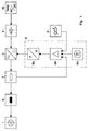
- the first exemplary embodiment of the invention shown in FIG. 1 shows a high-pressure discharge lamp 1 to be supplied, which can be a customary high-pressure mercury lamp, a high-pressure metal lamp or a high-pressure sodium lamp.
- a rectifier 4 which is connected to a network 10, is connected to the direct current input of the inverter 3.
- a frequency adjustment device 9 acts on the control input of the inverter 3.
- the operating frequency of the inverter is typically between 10 and 100 kHz.
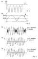
- the operating frequency of the inverter 3 is now modulated via the frequency adjustment device 9 in such a way that the time profile of the lamp current I L fed into the high-pressure discharge lamp is shown in FIG. 4c.
- the frequency swing of the frequency adjustment device 9 is adapted in this example so that the output power P varies by the nominal value (100%) fluctuating between the value 0 and 200%. On average, the power delivered to the lamp corresponds to the nominal power.
- the frequency adjustment device 9 consists of a voltage-frequency converter 9a, a control amplifier 9b and a modulation amplifier 9c.
- FIG. 4a shows the solution used in the prior art, which consists in applying a constant power to the high-pressure discharge lamp by generating a lamp current I L , which changes over time in a sinusoidal manner, by the inverter.
- the frequency of the lamp current I L is adapted in accordance with the previously determined resonance conditions of the respective high-pressure discharge lamp.
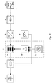
- Fig. 2 shows a variant of the embodiment shown in Fig. 1, which differs in that the inverter is now operated at a constant operating frequency and instead the inductor 7a in the output circuit of the inverter, which is designed as a transducer, is modulated.
- the modulation is carried out by means of an inductance adjusting device 7, which emits a time-varying output voltage and consists of a control amplifier 7b and a modulation generator 7c.
- the time course of the lamp current IL that occurs is shown in FIG. 4d.
- the time profile of the output power determined by the envelope of the lamp current corresponds to that as shown in FIG. 4b.
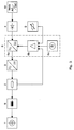
- the exemplary embodiment of the invention shown in FIG. 3 shows that the voltage present at the input of the inverter 3 is varied by means of a voltage adjusting device 6 such that the time profile of the lamp current IL shown in FIG. 4e results.
- the time profiles of FIGS. 4d and 4e are identical.
- the voltage adjustment device 6 consists of a modulation generator 6c, a control amplifier 6b and a voltage converter 6a.
- the nominal value of the output power of the inverter 3 can be influenced by another switching means, without otherwise changing the described modulation conditions.
- This measure allows the nominal value of the output power fed into the high-pressure discharge lamp to be varied, which enables the lamp to be dimmed.
- the setpoint Via the current measuring device 2 and a control amplifier 6b, 7b or 9b, the setpoint is compared with the actual value and corrected. It is possible to dim the illuminant down to 25% of the nominal luminous flux, which can result in a maximum energy saving of 65%.
- the solution according to the invention results in loss reductions of approximately 20% and increased light yields of approximately 10%.
Landscapes
- Circuit Arrangements For Discharge Lamps (AREA)
Priority Applications (3)
| Application Number | Priority Date | Filing Date | Title |
|---|---|---|---|
| EP95107865A EP0744883B1 (fr) | 1995-05-23 | 1995-05-23 | Dispositif et procédé de commande d'une lampe à décharge à haute pression |
| AT95107865T ATE261235T1 (de) | 1995-05-23 | 1995-05-23 | Verfahren bzw. vorrichtung zum betrieb einer hochdruckentladungslampe |
| DE59510867T DE59510867D1 (de) | 1995-05-23 | 1995-05-23 | Verfahren bzw. Vorrichtung zum Betrieb einer Hochdruckentladungslampe |
Applications Claiming Priority (1)
| Application Number | Priority Date | Filing Date | Title |
|---|---|---|---|
| EP95107865A EP0744883B1 (fr) | 1995-05-23 | 1995-05-23 | Dispositif et procédé de commande d'une lampe à décharge à haute pression |
Publications (2)
| Publication Number | Publication Date |
|---|---|
| EP0744883A1 true EP0744883A1 (fr) | 1996-11-27 |
| EP0744883B1 EP0744883B1 (fr) | 2004-03-03 |
Family
ID=8219281
Family Applications (1)
| Application Number | Title | Priority Date | Filing Date |
|---|---|---|---|
| EP95107865A Expired - Lifetime EP0744883B1 (fr) | 1995-05-23 | 1995-05-23 | Dispositif et procédé de commande d'une lampe à décharge à haute pression |
Country Status (3)
| Country | Link |
|---|---|
| EP (1) | EP0744883B1 (fr) |
| AT (1) | ATE261235T1 (fr) |
| DE (1) | DE59510867D1 (fr) |
Cited By (11)
| Publication number | Priority date | Publication date | Assignee | Title |
|---|---|---|---|---|
| EP0785702A3 (fr) * | 1996-01-16 | 1998-03-25 | Osram Sylvania Inc. | Méthode et appareil pour alimenter une lampe à décharge |
| EP0837620A2 (fr) * | 1996-10-21 | 1998-04-22 | Matsushita Electric Industrial Co., Ltd. | Méthode et dispositif pour alimenter une lampe à décharge à haute pression |
| WO1998035538A1 (fr) * | 1997-02-08 | 1998-08-13 | Robert Bosch Gmbh | Procede pour determiner la frequence de resonance d'un circuit electrique resonnant |
| EP0893943A1 (fr) * | 1997-07-24 | 1999-01-27 | F. Verdeyen N.V. | Onduleur à fréquence graduellement variable pour alimenter une lampe à décharge |
| US6124683A (en) * | 1999-04-14 | 2000-09-26 | Osram Sylvania Inc. | System for and method of operating a mercury free discharge lamp |
| EP1087644A1 (fr) * | 1999-09-27 | 2001-03-28 | Valeo Vision | Perfectionnements à la commande de l'alimentation de lampes à décharge notamment de projecteurs de véhicule automobile |
| US6229269B1 (en) | 1999-05-21 | 2001-05-08 | Osram Sylvania Inc. | System for and method of operating a discharge lamp |
| WO2003015480A1 (fr) * | 2001-08-10 | 2003-02-20 | Koninklijke Philips Electronics N.V. | Procede de melange de couleurs de lampes hid fonctionnant a des frequences vhf faisant intervenir une modulation du coefficient d'utilisation |
| WO2003017736A1 (fr) * | 2001-08-15 | 2003-02-27 | Koninklijke Philips Electronics N.V. | Technique d'utilisation d'une lampe a decharge a haute intensite faisant intervenir une modulation du cycle de service |
| WO2005098902A3 (fr) * | 2004-04-09 | 2006-03-16 | Koninkl Philips Electronics Nv | Lampe a vapeur de sodium haute pression |
| WO2007068603A1 (fr) * | 2005-12-14 | 2007-06-21 | Osram Gesellschaft mit beschränkter Haftung | Ensemble circuit et procede permettant de faire fonctionner des lampes a decharge haute pression |
Citations (4)
| Publication number | Priority date | Publication date | Assignee | Title |
|---|---|---|---|---|
| EP0386990A2 (fr) * | 1989-03-08 | 1990-09-12 | General Electric Company | Méthode de commande et circuit pour lampes à décharge |
| EP0439861A1 (fr) * | 1990-01-29 | 1991-08-07 | Koninklijke Philips Electronics N.V. | Dispositif de commutation |
| DE4234358A1 (de) * | 1992-10-12 | 1993-02-25 | Juerg Nigg | Verfahren zum betrieb einer gasentladungs- oder fluoreszenzlampe und vorschaltgeraet hierfuer sowie verwendungen hierfuer |
| EP0605052A1 (fr) * | 1992-12-28 | 1994-07-06 | Koninklijke Philips Electronics N.V. | Ballast pour lampe à décharge |
-
1995
- 1995-05-23 DE DE59510867T patent/DE59510867D1/de not_active Expired - Fee Related
- 1995-05-23 EP EP95107865A patent/EP0744883B1/fr not_active Expired - Lifetime
- 1995-05-23 AT AT95107865T patent/ATE261235T1/de not_active IP Right Cessation
Patent Citations (4)
| Publication number | Priority date | Publication date | Assignee | Title |
|---|---|---|---|---|
| EP0386990A2 (fr) * | 1989-03-08 | 1990-09-12 | General Electric Company | Méthode de commande et circuit pour lampes à décharge |
| EP0439861A1 (fr) * | 1990-01-29 | 1991-08-07 | Koninklijke Philips Electronics N.V. | Dispositif de commutation |
| DE4234358A1 (de) * | 1992-10-12 | 1993-02-25 | Juerg Nigg | Verfahren zum betrieb einer gasentladungs- oder fluoreszenzlampe und vorschaltgeraet hierfuer sowie verwendungen hierfuer |
| EP0605052A1 (fr) * | 1992-12-28 | 1994-07-06 | Koninklijke Philips Electronics N.V. | Ballast pour lampe à décharge |
Non-Patent Citations (1)
| Title |
|---|
| STORMBERG & SCHÄFER: "Excitation of acoustic instabilities in discharge lamps with pulsed supply voltage", LIGHTING RESEARCH & TECHNOLOGY, vol. 15, no. 3, March 1983 (1983-03-01), pages 127 - 132 * |
Cited By (16)
| Publication number | Priority date | Publication date | Assignee | Title |
|---|---|---|---|---|
| EP0785702A3 (fr) * | 1996-01-16 | 1998-03-25 | Osram Sylvania Inc. | Méthode et appareil pour alimenter une lampe à décharge |
| EP0837620B1 (fr) * | 1996-10-21 | 2003-03-19 | Matsushita Electric Industrial Co., Ltd. | Méthode et dispositif pour alimenter une lampe à décharge à haute pression |
| EP0837620A2 (fr) * | 1996-10-21 | 1998-04-22 | Matsushita Electric Industrial Co., Ltd. | Méthode et dispositif pour alimenter une lampe à décharge à haute pression |
| WO1998035538A1 (fr) * | 1997-02-08 | 1998-08-13 | Robert Bosch Gmbh | Procede pour determiner la frequence de resonance d'un circuit electrique resonnant |
| US6546346B1 (en) | 1997-02-08 | 2003-04-08 | Robert Bosch Gmbh | Method for determining the resonance frequency of an electric resonant circuit |
| EP0893943A1 (fr) * | 1997-07-24 | 1999-01-27 | F. Verdeyen N.V. | Onduleur à fréquence graduellement variable pour alimenter une lampe à décharge |
| US6124683A (en) * | 1999-04-14 | 2000-09-26 | Osram Sylvania Inc. | System for and method of operating a mercury free discharge lamp |
| US6229269B1 (en) | 1999-05-21 | 2001-05-08 | Osram Sylvania Inc. | System for and method of operating a discharge lamp |
| US6556463B1 (en) | 1999-09-27 | 2003-04-29 | Valeo Vision | Reduced electronic noise power supply to discharge lamps, especially for motor vehicle headlights |
| FR2799062A1 (fr) * | 1999-09-27 | 2001-03-30 | Valeo Vision | Perfectionnements a la commande de l'alimentation de lampes a decharge notamment de projecteur de vehicule automobile |
| EP1087644A1 (fr) * | 1999-09-27 | 2001-03-28 | Valeo Vision | Perfectionnements à la commande de l'alimentation de lampes à décharge notamment de projecteurs de véhicule automobile |
| WO2003015480A1 (fr) * | 2001-08-10 | 2003-02-20 | Koninklijke Philips Electronics N.V. | Procede de melange de couleurs de lampes hid fonctionnant a des frequences vhf faisant intervenir une modulation du coefficient d'utilisation |
| WO2003017736A1 (fr) * | 2001-08-15 | 2003-02-27 | Koninklijke Philips Electronics N.V. | Technique d'utilisation d'une lampe a decharge a haute intensite faisant intervenir une modulation du cycle de service |
| WO2005098902A3 (fr) * | 2004-04-09 | 2006-03-16 | Koninkl Philips Electronics Nv | Lampe a vapeur de sodium haute pression |
| WO2007068603A1 (fr) * | 2005-12-14 | 2007-06-21 | Osram Gesellschaft mit beschränkter Haftung | Ensemble circuit et procede permettant de faire fonctionner des lampes a decharge haute pression |
| US7839093B2 (en) | 2005-12-14 | 2010-11-23 | Osram Gesellschaft Mit Beschraenkter Haftung | Circuit arrangement with continuously oscillating modulated operating frequency, and method, for the operation of high-pressure gas discharge lamps |
Also Published As
| Publication number | Publication date |
|---|---|
| ATE261235T1 (de) | 2004-03-15 |
| DE59510867D1 (de) | 2004-04-08 |
| EP0744883B1 (fr) | 2004-03-03 |
Similar Documents
| Publication | Publication Date | Title |
|---|---|---|
| EP0548342B1 (fr) | Ballast d'exploitation en mode pulse de lampes luminescentes a gaz | |
| DE4017415C2 (de) | Schaltungsanordnung zum Betrieb einer Hochdruck-Entladungslampe für einen Fahrzeugscheinwerfer | |
| DE3101568C2 (de) | Schaltungsanordnung zum Betrieb von Niederdruckentladungslampen mit einstellbarem Lichtstrom | |
| DE69910415T2 (de) | Vorrichtung zur helligkeitsregelung einer leuchtstofflampe mit magnetischem ballast | |
| DE60210768T2 (de) | Vorschaltgerät für eine hochleistungsentladungslampe | |
| EP0356818B1 (fr) | Circuit alimentant une charge | |
| EP2296449A1 (fr) | PFC numérique parametrable | |
| DE4436825A1 (de) | Vorrichtung zum Betreiben einer Hochdruck-Gasentladungslampe | |
| DE69921616T2 (de) | Schaltungsanordnung | |
| EP0744883B1 (fr) | Dispositif et procédé de commande d'une lampe à décharge à haute pression | |
| EP0677982B1 (fr) | Procédé pour commander un ballast de lampes à décharge | |
| DE60215542T2 (de) | Verfahren und vorrichtung zum steuern einer entladungslampe | |
| EP0461441B1 (fr) | Procédé et circuit pour régler l'intensité lumineuse (atténuer) de lampes à décharge | |
| EP1465465B1 (fr) | Ballast électronique avec un circuit en pont complet | |
| DE3211240A1 (de) | Stabilisierungseinrichtung fuer gasentladungslampen | |
| DE60206991T2 (de) | Dimmbare kompakte Leuchtstofflampe und Betriebsvorrichtung einer Entladungslampe mit einem in den Vorheizungskreisen zugeordnetem Strombegrenzer | |
| DE60318580T2 (de) | Verfahren und vorrichtung zur identifizierung des typs einer entladungslampe | |
| DE602005004479T2 (de) | Elektronisches stromgespeistes Vorschaltgerät zur Kontrolle der Streifenbildung in Gasentladungslampen | |
| EP1181844A1 (fr) | Procede et ballaste servant a alimenter un emetteur de rayonnement u.v. basse pression | |
| EP1095543B1 (fr) | Ballast pour au moins une lampe a decharge, et procede pour faire fonctionner une tel ballast | |
| DE102004051162B4 (de) | Modulation eines PFC bei DC-Betrieb | |
| EP1354500B1 (fr) | Dispositif et procede de fonctionnement polyphase d'une lampe a decharge ou a vapeur metallique | |
| WO2007068603A1 (fr) | Ensemble circuit et procede permettant de faire fonctionner des lampes a decharge haute pression | |
| DE102016107578B4 (de) | Betriebsschaltung und Verfahren zum Betreiben wenigstens eines Leuchtmittels | |
| DE2848018A1 (de) | Verfahren und anordnung zur energieeinsparung beim betrieb von gasentladungslampen, insbesondere leuchtstofflampen |
Legal Events
| Date | Code | Title | Description |
|---|---|---|---|
| PUAI | Public reference made under article 153(3) epc to a published international application that has entered the european phase |
Free format text: ORIGINAL CODE: 0009012 |
|
| AK | Designated contracting states |
Kind code of ref document: A1 Designated state(s): AT BE CH DE DK ES FR GB GR IE IT LI LU NL SE |
|
| 17P | Request for examination filed |
Effective date: 19970507 |
|
| 17Q | First examination report despatched |
Effective date: 20000118 |
|
| GRAH | Despatch of communication of intention to grant a patent |
Free format text: ORIGINAL CODE: EPIDOS IGRA |
|
| GRAH | Despatch of communication of intention to grant a patent |
Free format text: ORIGINAL CODE: EPIDOS IGRA |
|
| GRAA | (expected) grant |
Free format text: ORIGINAL CODE: 0009210 |
|
| AK | Designated contracting states |
Kind code of ref document: B1 Designated state(s): AT BE CH DE DK ES FR GB GR IE IT LI LU NL SE |
|
| PG25 | Lapsed in a contracting state [announced via postgrant information from national office to epo] |
Ref country code: IE Free format text: LAPSE BECAUSE OF FAILURE TO SUBMIT A TRANSLATION OF THE DESCRIPTION OR TO PAY THE FEE WITHIN THE PRESCRIBED TIME-LIMIT Effective date: 20040303 Ref country code: GB Free format text: LAPSE BECAUSE OF FAILURE TO SUBMIT A TRANSLATION OF THE DESCRIPTION OR TO PAY THE FEE WITHIN THE PRESCRIBED TIME-LIMIT Effective date: 20040303 Ref country code: FR Free format text: LAPSE BECAUSE OF FAILURE TO SUBMIT A TRANSLATION OF THE DESCRIPTION OR TO PAY THE FEE WITHIN THE PRESCRIBED TIME-LIMIT Effective date: 20040303 |
|
| REG | Reference to a national code |
Ref country code: GB Ref legal event code: FG4D Free format text: NOT ENGLISH |
|
| RIC1 | Information provided on ipc code assigned before grant |
Ipc: 7H 05B 41/292 A |
|
| REG | Reference to a national code |
Ref country code: CH Ref legal event code: EP |
|
| REG | Reference to a national code |
Ref country code: IE Ref legal event code: FG4D Free format text: GERMAN |
|
| REF | Corresponds to: |
Ref document number: 59510867 Country of ref document: DE Date of ref document: 20040408 Kind code of ref document: P |
|
| PGFP | Annual fee paid to national office [announced via postgrant information from national office to epo] |
Ref country code: AT Payment date: 20040518 Year of fee payment: 10 |
|
| PG25 | Lapsed in a contracting state [announced via postgrant information from national office to epo] |
Ref country code: LU Free format text: LAPSE BECAUSE OF NON-PAYMENT OF DUE FEES Effective date: 20040523 |
|
| PG25 | Lapsed in a contracting state [announced via postgrant information from national office to epo] |
Ref country code: LI Free format text: LAPSE BECAUSE OF NON-PAYMENT OF DUE FEES Effective date: 20040531 Ref country code: CH Free format text: LAPSE BECAUSE OF NON-PAYMENT OF DUE FEES Effective date: 20040531 Ref country code: BE Free format text: LAPSE BECAUSE OF NON-PAYMENT OF DUE FEES Effective date: 20040531 |
|
| PG25 | Lapsed in a contracting state [announced via postgrant information from national office to epo] |
Ref country code: SE Free format text: LAPSE BECAUSE OF FAILURE TO SUBMIT A TRANSLATION OF THE DESCRIPTION OR TO PAY THE FEE WITHIN THE PRESCRIBED TIME-LIMIT Effective date: 20040603 Ref country code: GR Free format text: LAPSE BECAUSE OF FAILURE TO SUBMIT A TRANSLATION OF THE DESCRIPTION OR TO PAY THE FEE WITHIN THE PRESCRIBED TIME-LIMIT Effective date: 20040603 Ref country code: DK Free format text: LAPSE BECAUSE OF FAILURE TO SUBMIT A TRANSLATION OF THE DESCRIPTION OR TO PAY THE FEE WITHIN THE PRESCRIBED TIME-LIMIT Effective date: 20040603 |
|
| PGFP | Annual fee paid to national office [announced via postgrant information from national office to epo] |
Ref country code: NL Payment date: 20040609 Year of fee payment: 10 |
|
| PG25 | Lapsed in a contracting state [announced via postgrant information from national office to epo] |
Ref country code: ES Free format text: LAPSE BECAUSE OF FAILURE TO SUBMIT A TRANSLATION OF THE DESCRIPTION OR TO PAY THE FEE WITHIN THE PRESCRIBED TIME-LIMIT Effective date: 20040614 |
|
| PGFP | Annual fee paid to national office [announced via postgrant information from national office to epo] |
Ref country code: DE Payment date: 20040629 Year of fee payment: 10 |
|
| GBV | Gb: ep patent (uk) treated as always having been void in accordance with gb section 77(7)/1977 [no translation filed] |
Effective date: 20040303 |
|
| REG | Reference to a national code |
Ref country code: IE Ref legal event code: FD4D |
|
| BERE | Be: lapsed |
Owner name: PRAZISA INDUSTRIEELEKTRONIK G.M.B.H. Effective date: 20040531 |
|
| PLBE | No opposition filed within time limit |
Free format text: ORIGINAL CODE: 0009261 |
|
| STAA | Information on the status of an ep patent application or granted ep patent |
Free format text: STATUS: NO OPPOSITION FILED WITHIN TIME LIMIT |
|
| REG | Reference to a national code |
Ref country code: CH Ref legal event code: PL |
|
| EN | Fr: translation not filed | ||
| 26N | No opposition filed |
Effective date: 20041206 |
|
| PG25 | Lapsed in a contracting state [announced via postgrant information from national office to epo] |
Ref country code: IT Free format text: LAPSE BECAUSE OF NON-PAYMENT OF DUE FEES;WARNING: LAPSES OF ITALIAN PATENTS WITH EFFECTIVE DATE BEFORE 2007 MAY HAVE OCCURRED AT ANY TIME BEFORE 2007. THE CORRECT EFFECTIVE DATE MAY BE DIFFERENT FROM THE ONE RECORDED. Effective date: 20050523 Ref country code: AT Free format text: LAPSE BECAUSE OF NON-PAYMENT OF DUE FEES Effective date: 20050523 |
|
| PG25 | Lapsed in a contracting state [announced via postgrant information from national office to epo] |
Ref country code: NL Free format text: LAPSE BECAUSE OF NON-PAYMENT OF DUE FEES Effective date: 20051201 Ref country code: DE Free format text: LAPSE BECAUSE OF NON-PAYMENT OF DUE FEES Effective date: 20051201 |
|
| NLV4 | Nl: lapsed or anulled due to non-payment of the annual fee |
Effective date: 20051201 |