EP0744558B1 - Schwingungsdämpfer für eine Scheibenbremse - Google Patents
Schwingungsdämpfer für eine Scheibenbremse Download PDFInfo
- Publication number
- EP0744558B1 EP0744558B1 EP96107941A EP96107941A EP0744558B1 EP 0744558 B1 EP0744558 B1 EP 0744558B1 EP 96107941 A EP96107941 A EP 96107941A EP 96107941 A EP96107941 A EP 96107941A EP 0744558 B1 EP0744558 B1 EP 0744558B1
- Authority
- EP
- European Patent Office
- Prior art keywords
- vibration
- rotor
- oscillating
- vibration damping
- damping device
- Prior art date
- Legal status (The legal status is an assumption and is not a legal conclusion. Google has not performed a legal analysis and makes no representation as to the accuracy of the status listed.)
- Expired - Lifetime
Links
- 238000013016 damping Methods 0.000 title claims description 15
- 230000010355 oscillation Effects 0.000 claims 1
- 230000007246 mechanism Effects 0.000 description 8
- 238000001514 detection method Methods 0.000 description 7
- 230000003068 static effect Effects 0.000 description 2
- 230000001133 acceleration Effects 0.000 description 1
- 210000000078 claw Anatomy 0.000 description 1
Images

Classifications
-
- F—MECHANICAL ENGINEERING; LIGHTING; HEATING; WEAPONS; BLASTING
- F16—ENGINEERING ELEMENTS AND UNITS; GENERAL MEASURES FOR PRODUCING AND MAINTAINING EFFECTIVE FUNCTIONING OF MACHINES OR INSTALLATIONS; THERMAL INSULATION IN GENERAL
- F16D—COUPLINGS FOR TRANSMITTING ROTATION; CLUTCHES; BRAKES
- F16D65/00—Parts or details
- F16D65/14—Actuating mechanisms for brakes; Means for initiating operation at a predetermined position
-
- F—MECHANICAL ENGINEERING; LIGHTING; HEATING; WEAPONS; BLASTING
- F16—ENGINEERING ELEMENTS AND UNITS; GENERAL MEASURES FOR PRODUCING AND MAINTAINING EFFECTIVE FUNCTIONING OF MACHINES OR INSTALLATIONS; THERMAL INSULATION IN GENERAL
- F16D—COUPLINGS FOR TRANSMITTING ROTATION; CLUTCHES; BRAKES
- F16D65/00—Parts or details
- F16D65/0006—Noise or vibration control
- F16D65/0012—Active vibration dampers
-
- F—MECHANICAL ENGINEERING; LIGHTING; HEATING; WEAPONS; BLASTING
- F16—ENGINEERING ELEMENTS AND UNITS; GENERAL MEASURES FOR PRODUCING AND MAINTAINING EFFECTIVE FUNCTIONING OF MACHINES OR INSTALLATIONS; THERMAL INSULATION IN GENERAL
- F16D—COUPLINGS FOR TRANSMITTING ROTATION; CLUTCHES; BRAKES
- F16D65/00—Parts or details
-
- F—MECHANICAL ENGINEERING; LIGHTING; HEATING; WEAPONS; BLASTING
- F16—ENGINEERING ELEMENTS AND UNITS; GENERAL MEASURES FOR PRODUCING AND MAINTAINING EFFECTIVE FUNCTIONING OF MACHINES OR INSTALLATIONS; THERMAL INSULATION IN GENERAL
- F16D—COUPLINGS FOR TRANSMITTING ROTATION; CLUTCHES; BRAKES
- F16D65/00—Parts or details
- F16D65/14—Actuating mechanisms for brakes; Means for initiating operation at a predetermined position
- F16D65/16—Actuating mechanisms for brakes; Means for initiating operation at a predetermined position arranged in or on the brake
- F16D65/18—Actuating mechanisms for brakes; Means for initiating operation at a predetermined position arranged in or on the brake adapted for drawing members together, e.g. for disc brakes
-
- F—MECHANICAL ENGINEERING; LIGHTING; HEATING; WEAPONS; BLASTING
- F16—ENGINEERING ELEMENTS AND UNITS; GENERAL MEASURES FOR PRODUCING AND MAINTAINING EFFECTIVE FUNCTIONING OF MACHINES OR INSTALLATIONS; THERMAL INSULATION IN GENERAL
- F16F—SPRINGS; SHOCK-ABSORBERS; MEANS FOR DAMPING VIBRATION
- F16F15/00—Suppression of vibrations in systems; Means or arrangements for avoiding or reducing out-of-balance forces, e.g. due to motion
- F16F15/02—Suppression of vibrations of non-rotating, e.g. reciprocating systems; Suppression of vibrations of rotating systems by use of members not moving with the rotating systems
-
- F—MECHANICAL ENGINEERING; LIGHTING; HEATING; WEAPONS; BLASTING
- F16—ENGINEERING ELEMENTS AND UNITS; GENERAL MEASURES FOR PRODUCING AND MAINTAINING EFFECTIVE FUNCTIONING OF MACHINES OR INSTALLATIONS; THERMAL INSULATION IN GENERAL
- F16D—COUPLINGS FOR TRANSMITTING ROTATION; CLUTCHES; BRAKES
- F16D2121/00—Type of actuator operation force
- F16D2121/02—Fluid pressure
-
- F—MECHANICAL ENGINEERING; LIGHTING; HEATING; WEAPONS; BLASTING
- F16—ENGINEERING ELEMENTS AND UNITS; GENERAL MEASURES FOR PRODUCING AND MAINTAINING EFFECTIVE FUNCTIONING OF MACHINES OR INSTALLATIONS; THERMAL INSULATION IN GENERAL
- F16D—COUPLINGS FOR TRANSMITTING ROTATION; CLUTCHES; BRAKES
- F16D2129/00—Type of operation source for auxiliary mechanisms
- F16D2129/06—Electric or magnetic
- F16D2129/12—Electrostrictive or magnetostrictive elements, e.g. piezoelectric
Definitions
- the present invention relates to a vibration damping device for stopping squeaks of a disc brake by actively damping vibrations of its disc rotor (hereinafter referred to simply as "rotor"), which is a leading cause of squeaks of the disk brake, according to the preamble of claim 1.
- rotor disc rotor
- Unexamined Japanese Patent Publications 4-54324 and 4-54325 disclose one type of active vibration damping mechanisms for suppressing squeaks of a disc brake. They have a piezoelectric element for detecting vibrations of a brake pad (hereinafter simply referred to as "pad") and adapted to damp vibrations of the pad based on its detection signals to suppress squeaks.
- pad a piezoelectric element for detecting vibrations of a brake pad
- a leading cause of squeaks of a disc brake is the vibration of its rotor.
- conventional vibration damping mechanisms of this type are adapted to damp vibrations of a pad to indirectly suppress vibrations of the rotor. None of them can directly damp the vibration of the rotor. Thus, they cannot effectively reduce squeaks of disc brakes.
- the object of the present invention is to directly damp the vibration of the rotor.
- Rotor vibrations which cause squeaks of the disc brake, are canceled by directly oscillating the rotor with the oscillating means.
- squeaks can be suppressed more effectively than with a conventional vibration damping mechanism, which suppresses squeaks indirectly.
- Fig. 1 shows the first embodiment of the present invention.
- the vibration detecting means and the oscillating means of this embodiment are a photosensor 10 and an electromagnet 11, respectively, that are provided out of contact with the rotor 1 at a position other than the area where the caliper 6 is mounted.
- the photosensor 10 emits light against the end surface of the rotor 1 and receives the reflected light at its light intercepting portion to detect changes in light intensity and thus the vibration of the rotor.
- any other non-contact distance detector such as a magnetic type, an eddy current type or a capacitance type detector may be used.
- the electromagnet 11 can oscillate the rotor 1 in a non-contact manner by producing a magnetic force because the rotor is made of a magnetizable material. Since electromagnets can produce only an attraction force, it is necessary to provide an additional electromagnet on the other side of the electromagnet 11 or to magnetize the surface of the rotor facing the electromagnet 11 to produce both an attraction force and a repulsive force. With this arrangement, it is possible to produce oscillating force that can cancel out the vibration of the rotor by controlling the current applied to the electromagnet and its direction with the control circuit 9. While not shown, the photosensor 10 and the electromagnet 11 may be mounted on non-rotating members present around the rotor such as mounting brackets.
- non-contact oscillating means such as one that utilizes static energy may be used to oscillate the rotor.
- the vibration damping mechanism according to the present invention may be constructed by combining the first embodiment with the second embodiment.
- it may comprise a non-contact type vibration detecting means as shown in Fig. 1 and an oscillating means for oscillating the rotor through the pad as shown in Fig. 2.
- the vibration damping mechanism of the present invention reduces the vibration of not the pads but directly the rotor, it is possible to suppress squeaks of the disc brake more effectively than with conventional vibration damping mechanisms.
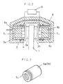
- Fig. 2 shows the first embodiment of the present invention.
- the vibration damping mechanism of this embodiment is used on an opposed-piston type disc brake having an inner pad 2a and an outer pad 2b that are brought into sliding contact with a rotor 1, pushed by respective pistons 5a and 5b mounted on a caliper 6.
- Piston seals 3 are provided which permit retraction of the pistons.
- Piston boots 4 seal the open ends of the cylinders.
- a piezoelectric element 7-1 is used as a vibration detecting means. It is pressed against the back of the inner pad 2a with a presser 8a mounted in the piston 5a to pick up vibrations of the rotor 1 transmitted through the inner pad 2a.
- the detection signals from the piezoelectric element 7-1 are inputted in a control circuit 9, which produces control signals based on the detection signals from the piezoelectric element 7-1 and applies them to a piezoelectric element 7-2 as an oscillating means.
- the piezoelectric element 7-2 produces an oscillating force which is transmitted to the rotor 1 through the outer pad 2b to stop the vibration of the rotor 1.
- the control circuit 9 controls the gain and phase of the oscillating force produced by the piezoelectric element 7-2 so that the vibration of the rotor 1 will be canceled by the oscillating force. More specifically, it produces control signals that can reduce the output signals from the piezoelectric element 7-1 to zero and applies such control signals to the piezoelectric element 7-2.
- the piezoelectric element 7-2 is pressed against the back of the outer pad 2b with a presser 8b. But as shown in Fig. 3, if a piezoelectric element 7-3 bonded to the pressing surface of one or each of the pistons 5a and 5b is used to detect vibrations or to apply an oscillating force, the pressers 8a and 8b are not necessary.
- the vibration of the rotor may be detected not by a piezoelectric element but by any other means such as an acceleration detector.
- the oscillating means is also not limited to a piezoelectric element but may be any other means that produces an oscillating force using magnetic, static or other energies.
- the vibration detecting means is provided on the inner side of the rotor and the oscillating means on the outer side. But they may be provided the other way around.
- the vibration damping mechanism of this embodiment can be used in a disc brake with a floating caliper, too.
- the vibration detecting means, or the oscillating means provided on the inner side of the rotor is pressed against the inner pad by the piston, while the other means, provided on the outer side where there is no piston, may be pressed against the outer pad, supported on e.g. outer claws of the caliper.
- the vibration detecting means should be provided on one side of the rotor, and the oscillating means be provided on the other side thereof.
- the vibration detecting means and the oscillating means are intended to detect vibrations of and apply oscillating force, not to the pads, but to the rotor, respectively.
- both the vibration detecting means and the oscillating means are provided on the same side of the rotor, so that the vibration of the rotor is detected and the oscillating force is applied to the rotor through the same pad.
- the vibration components detected by the vibration detecting means inevitably include not only the vibration of the rotor but the vibration of the pad caused by the oscillating force produced by the oscillating means. That is, the vibration detected does not precisely reflect the vibration of the rotor because it contains the vibration of the pad caused by the oscillating means.
- the vibration detecting means thus produces "inaccurate" detection signals. Since the oscillating means produces oscillating force based on the "inaccurate” detection signals, it is impossible to effectively cancel the vibration of the rotor.
- the vibration of the rotor is detected through a first one of the two pads, while the oscillating force is applied to the rotor through the other (second) pad.
- the vibration detected by the vibration detecting means does not contain the vibration of the second pad caused by the oscillating means, so that the vibration detecting means can produce "accurate" detection signals.
- the first pad is also vibrating more or less while the rotor is vibrating, so that the vibration detected by the vibration detection means contains "both the rotor vibration and the vibration of the first pad".
Landscapes
- Engineering & Computer Science (AREA)
- General Engineering & Computer Science (AREA)
- Mechanical Engineering (AREA)
- Physics & Mathematics (AREA)
- Acoustics & Sound (AREA)
- Aviation & Aerospace Engineering (AREA)
- Braking Arrangements (AREA)
- Vibration Prevention Devices (AREA)
Claims (4)
- Schwingungsdämpfungsvorrichtung zur Verwendung in einer Scheibenbremse, mit einem Schwingungserfassungsmittel zum Erfassen der Schwingungen eines Scheibenrotors (1), einem Oszillationsmittel, um den Scheibenrotor (1) in Schwingung zu versetzen, und einem Oszillationssteuermittel, um das Oszillationsmittel basierend auf der Ausgabe des Schwingungserfassungsmittels zu steuern,
dadurch gekennzeichnet, dass
das Schwingungserfassungsmittel ein kontaktfreier Abstandsdetektor (10) und/oder das Oszillationsmittel ein kontaktfreies Oszillationsmittel (11) ist, um eine Schwingungskraft zu erzeugen, die die Schwingung des Rotors (1) aufheben kann, indem der Strom, der dem kontaktfreien Oszillationsmittel (11) zugeführt wird, sowie dessen Richtung mit einer Steuerschaltung (9) gesteuert wird. - Schwingungsdämpfungsvorrichtung nach Anspruch 1,
dadurch gekennzeichnet, dass
der kontaktfreie Abstandsdetektor ein Photosensor (10), ein magnetischer Detektor, ein Wirbelstromdetektor oder ein kapazitiver Detektor ist. - Schwingungsdämpfungsvorrichtung nach Anspruch 1,
dadurch gekennzeichnet, dass
das kontaktfreie Oszillationsmittel ein Elektromagnet (11) ist. - Schwingungsdämpfungsvorrichtung nach Anspruch 1,
dadurch gekennzeichnet, dass
das kontaktfreie Schwingungserfassungsmittel mit einem Oszillationsmittel kombiniert ist, um den Rotor (1) über den Bremsklotz in Schwingung zu versetzen.
Applications Claiming Priority (3)
| Application Number | Priority Date | Filing Date | Title |
|---|---|---|---|
| JP12819595A JP3518054B2 (ja) | 1995-05-26 | 1995-05-26 | ディスクブレーキ用制振装置 |
| JP128195/95 | 1995-05-26 | ||
| JP12819595 | 1995-05-26 |
Publications (2)
| Publication Number | Publication Date |
|---|---|
| EP0744558A1 EP0744558A1 (de) | 1996-11-27 |
| EP0744558B1 true EP0744558B1 (de) | 2000-02-09 |
Family
ID=14978814
Family Applications (1)
| Application Number | Title | Priority Date | Filing Date |
|---|---|---|---|
| EP96107941A Expired - Lifetime EP0744558B1 (de) | 1995-05-26 | 1996-05-17 | Schwingungsdämpfer für eine Scheibenbremse |
Country Status (5)
| Country | Link |
|---|---|
| US (1) | US5660251A (de) |
| EP (1) | EP0744558B1 (de) |
| JP (1) | JP3518054B2 (de) |
| KR (1) | KR100219822B1 (de) |
| DE (1) | DE69606578T2 (de) |
Families Citing this family (62)
| Publication number | Priority date | Publication date | Assignee | Title |
|---|---|---|---|---|
| EP0748947B1 (de) * | 1995-06-13 | 1999-12-08 | Sumitomo Electric Industries, Ltd. | Scheibenbremse mit Schwingungsdämpfer |
| JPH09126254A (ja) * | 1995-10-30 | 1997-05-13 | Sumitomo Electric Ind Ltd | ディスクブレーキ用制振装置 |
| JP3687195B2 (ja) * | 1996-06-07 | 2005-08-24 | 住友電気工業株式会社 | ドラムブレーキ用制振装置 |
| JPH10184747A (ja) * | 1996-12-19 | 1998-07-14 | Sumitomo Electric Ind Ltd | 車両ブレーキ用制振装置 |
| GB2321090B (en) * | 1997-01-14 | 2000-08-23 | T & N Technology Ltd | Brake testing |
| DE19716569A1 (de) * | 1997-04-19 | 1998-10-22 | Porsche Ag | Einrichtung zum Bedämpfen von Schwingungen an einem Bremsbelag einer Scheibenbremse |
| DE19736275C2 (de) * | 1997-08-21 | 1999-07-01 | Itt Mfg Enterprises Inc | Vorrichtung zur Schwingungsreduktion an einer Bremse |
| WO1999023393A1 (en) * | 1997-11-03 | 1999-05-14 | Dana Corporation | Disc brake noise control |
| JP4540760B2 (ja) * | 1998-03-30 | 2010-09-08 | 日立オートモティブシステムズ株式会社 | ブレーキ制御装置 |
| DE19855467A1 (de) * | 1998-12-01 | 2000-06-08 | Lucas Ind Plc | Vorrichtung mit schwingungsgedämpftem Bauteil, insbesondere eine Bremse |
| JP2001027267A (ja) * | 1999-07-15 | 2001-01-30 | Sumitomo Electric Ind Ltd | キャリパボディ |
| DE10313990B4 (de) * | 2003-03-27 | 2005-10-13 | Daimlerchrysler Ag | Verfahren sowie Vorrichtung zur Reduktion von Bremsgeräuschen |
| US7644750B2 (en) * | 2005-09-20 | 2010-01-12 | Gm Global Technology Operations, Inc. | Method of casting components with inserts for noise reduction |
| US7975750B2 (en) * | 2004-10-08 | 2011-07-12 | GM Global Technology Operations LLC | Coulomb friction damped disc brake rotors |
| US8163399B2 (en) * | 2004-10-08 | 2012-04-24 | GM Global Technology Operations LLC | Damped products and methods of making and using the same |
| US8245758B2 (en) * | 2006-10-30 | 2012-08-21 | GM Global Technology Operations LLC | Coulomb damped disc brake rotor and method of manufacturing |
| US7775332B2 (en) * | 2005-09-15 | 2010-08-17 | Gm Global Technology Operations, Inc. | Bi-metal disc brake rotor and method of manufacturing |
| US7937819B2 (en) * | 2005-09-19 | 2011-05-10 | GM Global Technology Operations LLC | Method of manufacturing a friction damped disc brake rotor |
| DE102005006464A1 (de) * | 2005-02-12 | 2006-08-24 | Bayerische Motoren Werke Ag | Fahrzeugbremse sowie Fahrzeug mit Fahrzeugbremse |
| US20060266599A1 (en) * | 2005-05-26 | 2006-11-30 | Eric Denys | Control of brake noise by tuned mass dampers |
| US7594568B2 (en) | 2005-11-30 | 2009-09-29 | Gm Global Technology Operations, Inc. | Rotor assembly and method |
| US9174274B2 (en) | 2006-05-25 | 2015-11-03 | GM Global Technology Operations LLC | Low mass multi-piece sound dampened article |
| US8056233B2 (en) | 2006-06-27 | 2011-11-15 | GM Global Technology Operations LLC | Method of manufacturing an automotive component member |
| US20090020383A1 (en) * | 2006-06-27 | 2009-01-22 | Gm Global Technology Operations, Inc. | Damped part |
| US7905333B2 (en) * | 2006-08-08 | 2011-03-15 | Material Sciences Corporation | Brake insulator for disc brake pads |
| DE102006054751A1 (de) * | 2006-11-21 | 2008-06-05 | Tmd Friction Services Gmbh | Dämpfungsblech für eine Scheibenbremse |
| US9527132B2 (en) | 2007-07-20 | 2016-12-27 | GM Global Technology Operations LLC | Damped part with insert |
| US9534651B2 (en) * | 2007-07-20 | 2017-01-03 | GM Global Technology Operations LLC | Method of manufacturing a damped part |
| US8758902B2 (en) * | 2007-07-20 | 2014-06-24 | GM Global Technology Operations LLC | Damped product with an insert having a layer including graphite thereon and methods of making and using the same |
| US7950441B2 (en) * | 2007-07-20 | 2011-05-31 | GM Global Technology Operations LLC | Method of casting damped part with insert |
| US20100122880A1 (en) * | 2008-11-17 | 2010-05-20 | Gm Global Technology Operations, Inc. | Surface configurations for damping inserts |
| US7938378B2 (en) * | 2007-08-01 | 2011-05-10 | GM Global Technology Operations LLC | Damped product with insert and method of making the same |
| US7823763B2 (en) | 2007-08-01 | 2010-11-02 | Gm Global Technology Operations, Inc. | Friction welding method and products made using the same |
| US20090035598A1 (en) * | 2007-08-03 | 2009-02-05 | Gm Global Technology Operations, Inc. | Product with metallic foam and method of manufacturing the same |
| US8118079B2 (en) * | 2007-08-17 | 2012-02-21 | GM Global Technology Operations LLC | Casting noise-damped, vented brake rotors with embedded inserts |
| US8020300B2 (en) | 2007-08-31 | 2011-09-20 | GM Global Technology Operations LLC | Cast-in-place torsion joint |
| US8210232B2 (en) | 2007-09-20 | 2012-07-03 | GM Global Technology Operations LLC | Lightweight brake rotor and components with composite materials |
| US7836938B2 (en) * | 2007-09-24 | 2010-11-23 | Gm Global Technology Operations, Inc. | Insert with tabs and damped products and methods of making the same |
| US8028739B2 (en) | 2007-10-29 | 2011-10-04 | GM Global Technology Operations LLC | Inserts with holes for damped products and methods of making and using the same |
| US8091609B2 (en) * | 2008-01-04 | 2012-01-10 | GM Global Technology Operations LLC | Method of forming casting with frictional damping insert |
| US8104162B2 (en) | 2008-04-18 | 2012-01-31 | GM Global Technology Operations LLC | Insert with filler to dampen vibrating components |
| US8960382B2 (en) | 2008-04-18 | 2015-02-24 | GM Global Technology Operations LLC | Chamber with filler material to dampen vibrating components |
| US20090260931A1 (en) * | 2008-04-18 | 2009-10-22 | Gm Global Technology Operations, Inc. | Filler material to dampen vibrating components |
| US9163682B2 (en) * | 2008-07-24 | 2015-10-20 | GM Global Technology Operations LLC | Friction damped brake drum |
| US9500242B2 (en) * | 2008-12-05 | 2016-11-22 | GM Global Technology Operations LLC | Component with inlay for damping vibrations |
| US9127734B2 (en) * | 2009-04-08 | 2015-09-08 | GM Global Technology Operations LLC | Brake rotor with intermediate portion |
| US20100276236A1 (en) * | 2009-05-01 | 2010-11-04 | Gm Global Technology Operations, Inc. | Damped product and method of making the same |
| US20100282550A1 (en) * | 2009-05-07 | 2010-11-11 | Gm Global Technology Operations, Inc. | Mode altering insert for vibration reduction in components |
| US20100294063A1 (en) * | 2009-05-22 | 2010-11-25 | Gm Global Technology Operations, Inc. | Friction damped gears |
| US8714232B2 (en) | 2010-09-20 | 2014-05-06 | GM Global Technology Operations LLC | Method of making a brake component |
| ITTO20130307A1 (it) | 2013-04-17 | 2014-10-18 | Itt Italia Srl | Metodo per realizzare un elemento frenante, in particolare una pastiglia freno, sensorizzato, pastiglia freno sensorizzata, impianto frenante di veicolo e metodo associato |
| DE102014109699A1 (de) * | 2014-07-10 | 2016-01-14 | Federal-Mogul Bremsbelag Gmbh | Bremsbelag mit Vorrichtung zur Reduzierung von Geräuschen |
| ES2739897T3 (es) | 2014-09-08 | 2020-02-04 | Itt Italia Srl | Método para fabricar un elemento de frenado sensorizado, en particular una pastilla de freno y una pastilla de freno sensorizada obtenida de este modo |
| US9939035B2 (en) | 2015-05-28 | 2018-04-10 | Itt Italia S.R.L. | Smart braking devices, systems, and methods |
| ITUB20153706A1 (it) | 2015-09-17 | 2017-03-17 | Itt Italia Srl | Dispositivo frenante per veicolo pesante e metodo di prevenzione del surriscaldamento dei freni in un veicolo pesante |
| ITUB20153709A1 (it) | 2015-09-17 | 2017-03-17 | Itt Italia Srl | Dispositivo di analisi e gestione dei dati generati da un sistema frenante sensorizzato per veicoli |
| JP6862731B2 (ja) * | 2016-03-01 | 2021-04-21 | ヤマハ株式会社 | 制振装置 |
| ITUA20161336A1 (it) | 2016-03-03 | 2017-09-03 | Itt Italia Srl | Dispositivo e metodo per il miglioramento delle prestazioni di un sistema antibloccaggio e antiscivolamento di un veicolo |
| IT201600077944A1 (it) | 2016-07-25 | 2018-01-25 | Itt Italia Srl | Dispositivo per il rilevamento della coppia residua di frenatura in un veicolo equipaggiato con freni a disco |
| IT201900015839A1 (it) | 2019-09-06 | 2021-03-06 | Itt Italia Srl | Pastiglia freno per veicoli e suo processo di produzione |
| IT202000013408A1 (it) | 2020-06-05 | 2021-12-05 | Itt Italia Srl | Pastiglia freno intelligente di veicolo e suo metodo di manifattura |
| CN117377603A (zh) | 2021-05-25 | 2024-01-09 | 意大利Itt有限责任公司 | 用于估计车辆的被制动元件和制动元件之间的残余扭矩的方法和装置 |
Family Cites Families (5)
| Publication number | Priority date | Publication date | Assignee | Title |
|---|---|---|---|---|
| JPH02113143A (ja) * | 1988-10-19 | 1990-04-25 | Nec Corp | テーブル |
| US5032753A (en) * | 1989-02-28 | 1991-07-16 | Brother Kogyo Kabushiki Kaisha | Piezoelectric transducer and an ultrasonic motor using the piezoelectric transducer |
| JPH0454324A (ja) * | 1990-06-22 | 1992-02-21 | Aisin Seiki Co Ltd | 車両用制動装置 |
| JPH0454325A (ja) * | 1990-06-22 | 1992-02-21 | Aisin Seiki Co Ltd | 車両用制動装置 |
| US5394290A (en) * | 1993-07-06 | 1995-02-28 | Alliedsignal Inc. | Active tuned magnetic flux rate feedback sensing arrangement |
-
1995
- 1995-05-26 JP JP12819595A patent/JP3518054B2/ja not_active Expired - Fee Related
-
1996
- 1996-05-16 US US08/648,695 patent/US5660251A/en not_active Expired - Fee Related
- 1996-05-17 EP EP96107941A patent/EP0744558B1/de not_active Expired - Lifetime
- 1996-05-17 DE DE69606578T patent/DE69606578T2/de not_active Expired - Fee Related
- 1996-05-25 KR KR1019960017861A patent/KR100219822B1/ko not_active Expired - Fee Related
Also Published As
| Publication number | Publication date |
|---|---|
| KR960041793A (ko) | 1996-12-19 |
| JPH08320038A (ja) | 1996-12-03 |
| JP3518054B2 (ja) | 2004-04-12 |
| US5660251A (en) | 1997-08-26 |
| EP0744558A1 (de) | 1996-11-27 |
| KR100219822B1 (ko) | 1999-09-01 |
| DE69606578T2 (de) | 2000-10-19 |
| DE69606578D1 (de) | 2000-03-16 |
Similar Documents
| Publication | Publication Date | Title |
|---|---|---|
| US5660251A (en) | Vibration damping device for disc brake | |
| US5860494A (en) | Vibration damper for use in disk brake | |
| JPH10184747A (ja) | 車両ブレーキ用制振装置 | |
| US5092566A (en) | Rubber bearing having hydraulic damping means | |
| US5960912A (en) | Vibration damper for a drum brake | |
| US6186288B1 (en) | Disc brake | |
| KR101953243B1 (ko) | 자기유변탄성체를 이용한 디스크 브레이크 시스템 | |
| EP0874173B1 (de) | Vibrationsdämpfungseinrichtung | |
| US4886147A (en) | Brake arrangement | |
| JP3580019B2 (ja) | ディスクブレーキ用制振装置 | |
| JPH01150032A (ja) | 制動装置 | |
| JPH0454324A (ja) | 車両用制動装置 | |
| JP3518021B2 (ja) | 車両用制動装置 | |
| GB2115892A (en) | Disc brake | |
| WO1999023393A1 (en) | Disc brake noise control | |
| GB2039644A (en) | Vehicle friction brake | |
| KR20020009664A (ko) | 완충부재가 구비된 디스크 브레이크 | |
| JPH0125303B2 (de) | ||
| KR200196342Y1 (ko) | 디스크 브레이크의 캘리퍼 댐핑장치 | |
| JP2691895B2 (ja) | 振動モーター | |
| JP2587544Y2 (ja) | ディスクブレーキ用パッド | |
| KR0155118B1 (ko) | 방열성이 강화되고 정적 언바란스량 조정이 용이한 브레이크드럼 | |
| KR100779485B1 (ko) | 디스크 브레이크 | |
| JPH01126442A (ja) | ディスクブレーキ装置 | |
| KR19990019133U (ko) | 디스크 브레이크의 소음저감구조 |
Legal Events
| Date | Code | Title | Description |
|---|---|---|---|
| PUAI | Public reference made under article 153(3) epc to a published international application that has entered the european phase |
Free format text: ORIGINAL CODE: 0009012 |
|
| AK | Designated contracting states |
Kind code of ref document: A1 Designated state(s): DE FR GB |
|
| 17P | Request for examination filed |
Effective date: 19961126 |
|
| 17Q | First examination report despatched |
Effective date: 19980216 |
|
| GRAG | Despatch of communication of intention to grant |
Free format text: ORIGINAL CODE: EPIDOS AGRA |
|
| GRAG | Despatch of communication of intention to grant |
Free format text: ORIGINAL CODE: EPIDOS AGRA |
|
| GRAH | Despatch of communication of intention to grant a patent |
Free format text: ORIGINAL CODE: EPIDOS IGRA |
|
| GRAH | Despatch of communication of intention to grant a patent |
Free format text: ORIGINAL CODE: EPIDOS IGRA |
|
| GRAA | (expected) grant |
Free format text: ORIGINAL CODE: 0009210 |
|
| AK | Designated contracting states |
Kind code of ref document: B1 Designated state(s): DE FR GB |
|
| REF | Corresponds to: |
Ref document number: 69606578 Country of ref document: DE Date of ref document: 20000316 |
|
| ET | Fr: translation filed | ||
| PLBE | No opposition filed within time limit |
Free format text: ORIGINAL CODE: 0009261 |
|
| STAA | Information on the status of an ep patent application or granted ep patent |
Free format text: STATUS: NO OPPOSITION FILED WITHIN TIME LIMIT |
|
| 26N | No opposition filed | ||
| REG | Reference to a national code |
Ref country code: GB Ref legal event code: IF02 |
|
| REG | Reference to a national code |
Ref country code: GB Ref legal event code: 746 Effective date: 20040728 |
|
| REG | Reference to a national code |
Ref country code: FR Ref legal event code: D6 |
|
| PGFP | Annual fee paid to national office [announced via postgrant information from national office to epo] |
Ref country code: GB Payment date: 20070516 Year of fee payment: 12 |
|
| PGFP | Annual fee paid to national office [announced via postgrant information from national office to epo] |
Ref country code: FR Payment date: 20070510 Year of fee payment: 12 |
|
| PGFP | Annual fee paid to national office [announced via postgrant information from national office to epo] |
Ref country code: DE Payment date: 20080522 Year of fee payment: 13 |
|
| GBPC | Gb: european patent ceased through non-payment of renewal fee |
Effective date: 20080517 |
|
| REG | Reference to a national code |
Ref country code: FR Ref legal event code: ST Effective date: 20090119 |
|
| PG25 | Lapsed in a contracting state [announced via postgrant information from national office to epo] |
Ref country code: FR Free format text: LAPSE BECAUSE OF NON-PAYMENT OF DUE FEES Effective date: 20080602 |
|
| PG25 | Lapsed in a contracting state [announced via postgrant information from national office to epo] |
Ref country code: GB Free format text: LAPSE BECAUSE OF NON-PAYMENT OF DUE FEES Effective date: 20080517 |
|
| PG25 | Lapsed in a contracting state [announced via postgrant information from national office to epo] |
Ref country code: DE Free format text: LAPSE BECAUSE OF NON-PAYMENT OF DUE FEES Effective date: 20091201 |