EP0744326A1 - Wiper blade rubber for a motor vehicle windscreen wiper - Google Patents
Wiper blade rubber for a motor vehicle windscreen wiper Download PDFInfo
- Publication number
- EP0744326A1 EP0744326A1 EP96107476A EP96107476A EP0744326A1 EP 0744326 A1 EP0744326 A1 EP 0744326A1 EP 96107476 A EP96107476 A EP 96107476A EP 96107476 A EP96107476 A EP 96107476A EP 0744326 A1 EP0744326 A1 EP 0744326A1
- Authority
- EP
- European Patent Office
- Prior art keywords
- blade
- longitudinal
- heel
- wiper
- faces
- Prior art date
- Legal status (The legal status is an assumption and is not a legal conclusion. Google has not performed a legal analysis and makes no representation as to the accuracy of the status listed.)
- Withdrawn
Links
Images


Classifications
-
- B—PERFORMING OPERATIONS; TRANSPORTING
- B60—VEHICLES IN GENERAL
- B60S—SERVICING, CLEANING, REPAIRING, SUPPORTING, LIFTING, OR MANOEUVRING OF VEHICLES, NOT OTHERWISE PROVIDED FOR
- B60S1/00—Cleaning of vehicles
- B60S1/02—Cleaning windscreens, windows or optical devices
- B60S1/04—Wipers or the like, e.g. scrapers
- B60S1/32—Wipers or the like, e.g. scrapers characterised by constructional features of wiper blade arms or blades
- B60S1/38—Wiper blades
- B60S2001/3827—Wiper blades characterised by the squeegee or blade rubber or wiping element
- B60S2001/3829—Wiper blades characterised by the squeegee or blade rubber or wiping element characterised by the material of the squeegee or coating thereof
-
- B—PERFORMING OPERATIONS; TRANSPORTING
- B60—VEHICLES IN GENERAL
- B60S—SERVICING, CLEANING, REPAIRING, SUPPORTING, LIFTING, OR MANOEUVRING OF VEHICLES, NOT OTHERWISE PROVIDED FOR
- B60S1/00—Cleaning of vehicles
- B60S1/02—Cleaning windscreens, windows or optical devices
- B60S1/04—Wipers or the like, e.g. scrapers
- B60S1/32—Wipers or the like, e.g. scrapers characterised by constructional features of wiper blade arms or blades
- B60S1/38—Wiper blades
- B60S2001/3827—Wiper blades characterised by the squeegee or blade rubber or wiping element
- B60S2001/3836—Wiper blades characterised by the squeegee or blade rubber or wiping element characterised by cross-sectional shape
Definitions
- the invention relates to a wiper blade for a wiper blade of a motor vehicle.
- the invention relates more particularly to a squeegee wiping the killer comprising a flexible longitudinal upper heel, reinforced, for fixing the squeegee and a longitudinal lower wiper blade connected to the heel so as to pivot relative to the latter around a longitudinal axis.
- Such a wiper blade is for example produced in the form of a single element molded by extrusion.
- the object of the present invention is to propose a new design of a wiping squeegee of the type mentioned above which makes it possible to remedy this drawback.
- the invention provides a wiper blade characterized in that means are provided for reducing the contact area between said surface of the blade and the portion opposite the window to be wiped .
- FIG. 1 shows a wiping squeegee 10 which essentially consists of an upper fixing heel 14 and a lower wiping blade 12.
- the two parts 12 and 14 are made from a single piece of material molded by extrusion in an elastomeric material.
- the upper heel 14 has a generally rectangular parallelepiped shape which extends longitudinally and which is delimited laterally by two opposite faces 16 parallel to the general longitudinal axis of the squeegee 10 which has a symmetry of design with respect to a median vertical plane P .
- the heel 14 is also delimited by an upper horizontal plane face 18 and by a lower horizontal plane face 20.
- Each of the faces 16 has two upper longitudinal grooves 22, each of which receives a reinforcing vertebra 24 and two lower longitudinal grooves 26, the bottoms of which delimit a band 28 connecting the upper part of the heel 14 with two opposite lateral wings 30.
- the lower blade 12 has a profile in the form of an inverted arrow which is delimited laterally by two opposite longitudinal faces 32 each of which has a slight convexity facing the window to be wiped.
- the blade 12 is also delimited at its upper part by an upper horizontal face 34 which extends opposite the lower horizontal face 20 of the heel 14.
- the blade 12 is hingedly connected to the heel 14 by a median longitudinal connecting strip 36 which extends between the horizontal facing faces 20 and 34 and which allows the blade 12 to pivot relative to the heel 14 around a longitudinal axis XX.
- the wiping blade 12 is also delimited by two parallel and opposite lateral facets 38 which extend vertically in the same plane as the opposite lateral faces 16 of the heel 14.
- the opposite longitudinal faces 32 of the blade 12 terminate at the lower part by the longitudinal wiping edge 40 of the squeegee 10.
- the squeegee 10 has the configuration illustrated in FIG. 2 in which the blade 12 is inclined relative to the heel 14 and in which only the edge 40 is in contact with the window to be wiped in a direction of movement D.
- one of the longitudinal faces 32 strikes the window to be wiped 44.
- the invention aims to provide means for eliminating, or at least reducing these harmful noise to passenger comfort.
- each of the lateral edges of the upper horizontal face 34 of the blade 12 is fitted with an elastically deformable lip 46 which is liable to come cooperate gradually and regularly with the portion facing the lower horizontal face 20 of the wings 30 of the heel 14.
- the upper face 34 is itself inclined so as to give an inverted V shape to this upper face to produce two lips 46 of larger dimensions and greater flexibility to dampen the phenomena even more. of shocks and impacts.
- the horizontal upper face 34 of the wiping blade 12 comprises a series of studs 48 distributed along the wiping blade.
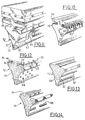
- FIGS. 7 to 10 show different embodiments of notches 50 formed in the horizontal face upper 34.
- the notches extend in a transverse direction perpendicular to the pivot axis of the blade 12 and they open into the lateral facets 38 of the upper part of the wiping blade 12 .
- the bottom 52 of the notches 50 is parallel to the plane of the upper horizontal face 34.
- the bottoms 52 of the notches 50 are inclined relative to the plane of the upper horizontal face 34 of the blade 12.
- each notch 50 is vertical and perpendicular to the plane of the upper horizontal face 34 while, in FIG. 9, the transverse edges 54 are inclined relative to a vertical plane.
- notches 60 equivalent to the notches 50 but which are formed in the lower horizontal face 20 of the upper heel, the notches 60 possibly being associated with notches 50 formed in the upper horizontal face 34 of the blade 12.
- lips 46 have been shown on the wings 30 similar to those shown in FIG. 5 as well as a first embodiment of means for reducing the area of contact between the opposite longitudinal faces 32 of the blade 12 and the window to be wiped.
- the means for reducing the contact area consist of two longitudinal lips 62 each formed on a convex longitudinal face 32.
- the lips 62 can be produced in the form of sections of lips by means of cutouts 64 distributed regularly along the lips 62.
- each of the opposite longitudinal and convex faces 32 is provided with a series of studs 66 formed in relief.
- the raised parts are produced in the form of longitudinal ribs 68 which, in the embodiment of FIG. 13, are two in number and are parallel on each of the longitudinal faces. convex and opposite 32 of the blade 12.
- the ribs 68 are produced in an interrupted manner to form sections of ribs further reducing the contact area in the event of an impact with the surface of the window to be wiped.
Abstract
Description
L'invention concerne une raclette d'essuyage pour un balai d'essuie-glace de véhicule automobile.The invention relates to a wiper blade for a wiper blade of a motor vehicle.
L'invention concerne plus particulièrement une raclette d'essuyage du tue comportant un talon souple supérieur longitudinal, renforcé, de fixation de la raclette et une lame inférieure longitudinale d'essuyage reliée au talon de manière à pivoter par rapport à ce dernier autour d'un axe longitudinal.The invention relates more particularly to a squeegee wiping the killer comprising a flexible longitudinal upper heel, reinforced, for fixing the squeegee and a longitudinal lower wiper blade connected to the heel so as to pivot relative to the latter around a longitudinal axis.
Une telle raclette d'essuyage est par exemple réalisée sous la forme d'un élément unique moulé par extrusion.Such a wiper blade is for example produced in the form of a single element molded by extrusion.
Lorsqu'une telle raclette équipe un essuie-glace du type à balayage alterné, et lors de l'inversion du sens de balayage, qu'il s'agisse d'un balayage en rotation ou d'un balayage linéaire, il se produit une inversion du sens de pivotement de la lame d'essuyage par rapport au talon d'essuyage au cours de laquelle une surface de la lame d'essuyage vient en contact avec une portion en vis-à-vis du talon et au cours de laquelle une surface de la lame d'essuyage vient en contact avec la vitre à essuyer.When such a squeegee equips a wiper of the alternating-sweeping type, and when the direction of sweeping is reversed, whether it is a rotary sweep or a linear sweep, a reversing the direction of pivoting of the wiping blade with respect to the wiping heel during which a surface of the wiping blade comes into contact with a portion facing the heel and during which a surface of the wiping blade comes into contact with the glass to be wiped.
Ces phénomènes d'inversion de sens de pivotement et de venue en contact seront explicités plus en détail dans la description détaillée qui va suivre.These phenomena of reversal of direction of pivoting and coming into contact will be explained in more detail in the detailed description which follows.
Ces venues en contact ont pour conséquence de créer des chocs entre différentes surfaces qui sont générateurs de bruits nuisibles au confort d'utilisation du véhicule.These coming into contact have the consequence of creating shocks between different surfaces which generate noise harmful to the comfort of use of the vehicle.
Ces bruits de fonctionnement lors des phases d'inversion ou de retournement de la lame d'essuyage sont particulièrement nuisibles en ce qu'ils revêtent, pour les passagers, un caractère répétitif et régulier.These operating noises during the inversion or inversion phases of the wiping blade are particularly harmful in that they assume, for the passengers, a repetitive and regular character.
La présente invention a pour but de proposer une nouvelle conception d'une raclette d'essuyage du type mentionné précédemment qui permet de remédier à cet inconvénient.The object of the present invention is to propose a new design of a wiping squeegee of the type mentioned above which makes it possible to remedy this drawback.
Dans ce but, l'invention propose une raclette d'essuyage caractérisée en ce qu'il est prévu des moyens pour réduire l'aire de contact entre ladite surface de la lame et la portion en vis-à-vis de la vitre à essuyer.To this end, the invention provides a wiper blade characterized in that means are provided for reducing the contact area between said surface of the blade and the portion opposite the window to be wiped .
Selon d'autres caractéristiques de l'invention :
- la lame est délimitée par deux faces longitudinales opposées reliées entre elles par un bord d'essuyage et chacune de ces faces comporte des parties en relief susceptibles de coopérer avec la vitre à essuyer lors de l'inversion du sens de pivotement ;
- les parties en relief sont des plots répartis sur chacune des deux faces longitudinales opposées de la lame ;
- les parties en relief comportent au moins une nervure longitudinale agencée sur chacune des deux faces longitudinales opposées ;
- chaque nervure est interrompue pour constituer des tronçons de nervure répartis longitudinalement ;
- les parties en relief sont des lèvres longitudinales déformables élastiquement ;
- chacune des deux faces longitudinales opposées de la lame présente une convexité tournée vers la vitre à essuyer.
- the blade is delimited by two opposite longitudinal faces connected together by a wiping edge and each of these faces has raised parts capable of cooperating with the window to be wiped during the reversal of the direction of pivoting;
- the raised parts are studs distributed on each of the two opposite longitudinal faces of the blade;
- the raised parts comprise at least one longitudinal rib arranged on each of the two opposite longitudinal faces;
- each rib is interrupted to form rib sections distributed longitudinally;
- the raised parts are elastically deformable longitudinal lips;
- each of the two opposite longitudinal faces of the blade has a convexity facing the window to be wiped.
D'autres caractéristiques et avantages de l'invention apparaîtront à la lecture de la description détaillée qui va suivre pour la compréhension de laquelle on se reportera aux dessins annexés dans lesquels :
- La figure 1 est une vue en perspective d'un tronçon d'une raclette d'essuyage conforme à l'état de la technique ;
- la figure 2 est une vue similaire à celle de la figure 1 qui illustre la raclette en cours de balayage d'une vitre ;
- la figure 3 est une vue similaire à celle des figures 1 et 2 qui illustrent le phénomène de chocs au moment de l'inversion du sens de pivotement de la lame par rapport au talon de la raclette ;
- les figures 4 à 14 sont des vues schématiques partielles similaires à celles de la figure 1 qui illustrent différents modes de réalisation des moyens permettent de réduire les bruits résultant des chocs par réduction des aires de contact entre différentes surfaces de la raclette d'essuyage et entre cette dernière et la vitre à essuyer.
- Figure 1 is a perspective view of a section of a wiper blade according to the prior art;
- Figure 2 is a view similar to that of Figure 1 which illustrates the squeegee during scanning of a window;
- FIG. 3 is a view similar to that of FIGS. 1 and 2 which illustrate the phenomenon of shocks upon reversing the direction of pivoting of the blade relative to the heel of the squeegee;
- Figures 4 to 14 are partial schematic views similar to those of Figure 1 which illustrate different embodiments of the means used to reduce the noise resulting from impacts by reducing the contact areas between different surfaces of the wiper blade and between the latter and the glass to be wiped.
On a représenté sur la figure 1 une raclette d'essuyage 10 qui est constituée pour l'essentiel par un talon supérieur de fixation 14 et par une lame inférieure d'essuyage 12.FIG. 1 shows a
Les deux parties 12 et 14 sont réalisées venues de matière en une seule pièce moulée par extrusion dans un matériau élastomère.The two
Le talon supérieur 14 présente une forme générale parallélépipédique rectangle qui s'étend longitudinalement et qui est délimitée latéralement par deux faces opposées 16 parallèles à l'axe longitudinal général de la raclette 10 qui présente une symétrie de conception par rapport à un plan vertical médian P.The
Le talon 14 est également délimité par une face plane horizontale supérieure 18 et par une face plane horizontale inférieure 20.The
Chacune des faces 16 comporte deux rainures longitudinales supérieures 22 dont chacune reçoit une vertèbre de renfort 24 et deux rainures longitudinales inférieures 26 dont les fonds délimitent une bande 28 de liaison de la partie supérieure du talon 14 avec deux ailes latérales opposées 30.Each of the
Selon une conception connue, la lame inférieure 12 présente un profil en forme de flèche inversée qui est délimitée latéralement par deux faces longitudinales opposées 32 dont chacune présente une légère convexité tournée vers la vitre à essuyer.According to a known design, the
La lame 12 est également délimitée à sa partie supérieure par une face horizontale supérieure 34 qui s'étend en vis-à-vis de la face horizontale inférieure 20 du talon 14.The
La lame 12 est reliée de manière articulée au talon 14 par une bande longitudinale médiane de liaison 36 qui s'étend entre les faces horizontales en vis-à-vis 20 et 34 et qui permet à la lame 12 de pivoter par rapport au talon 14 autour d'un axe longitudinal X-X.The
A sa partie supérieure, la lame d'essuyage 12 est également délimitée par deux facettes latérales parallèles et opposées 38 qui s'étendent verticalement dans le même plan que les faces latérales opposées 16 du talon 14.At its upper part, the
Les faces longitudinales opposées 32 de la lame 12 se terminent à la partie inférieure par le bord longitudinal d'essuyage 40 de la raclette 10.The opposite
En fonctionnement de balayage, la raclette 10 présente la conformation illustrée sur la figure 2 dans laquelle la lame 12 est inclinée par rapport au talon 14 et dans laquelle seul le bord 40 est en contact avec la vitre à essuyer dans une direction de déplacement D.In scanning operation, the
En fin d'une course de balayage, il se produit une inversion de la direction D de balayage qui provoque différents chocs au niveau de la raclette d'essuyage 10.At the end of a wiping stroke, there is an inversion of the wiping direction D which causes different impacts at the level of the
Comme on peut le voir sur la figure 3, l'une des faces longitudinales 32 vient percuter la vitre à essuyer 44.As can be seen in FIG. 3, one of the
De même, une portion de la face horizontale supérieure 34 vient percuter la face horizontale inférieure 20 du talon 14, l'aile 30 pouvant elle-même venir percuter la portion en vis-à-vis de la partie supérieure du talon 14.Likewise, a portion of the upper
Ces différents chocs sont générateurs de bruits et l'invention a pour but de proposer des moyens pour supprimer, ou tout au moins réduire ces bruits nuisibles au confort des passagers.These different shocks generate noise and the invention aims to provide means for eliminating, or at least reducing these harmful noise to passenger comfort.
Aux figures 4 et 5, la partie supérieure de la lame d'essuyage 12 a été modifiée de manière que chacun des bords latéraux de la face horizontale supérieure 34 de la lame 12 soit équipé d'une lèvre déformable élastiquement 46 qui est susceptible de venir coopérer de manière progressive et régulière avec la portion en vis-à-vis de la face horizontale inférieure 20 des ailes 30 du talon 14.In FIGS. 4 and 5, the upper part of the
Dans le cas de la figure 4, la face supérieure 34 est elle-même inclinée de manière à conférer une forme en V inversée à cette face supérieure pour réaliser deux lèvres 46 de plus grandes dimensions et de plus grande souplesse pour amortir encore davantage les phénomènes de chocs et d'impacts.In the case of FIG. 4, the
Dans le mode de réalisation illustré sur la figure 6, la face supérieure horizontale 34 de la lame d'essuyage 12 comporte une série de plots 48 répartis le long de la lame d'essuyage.In the embodiment illustrated in FIG. 6, the horizontal
Lors des phases d'inversion du sens de pivotement de la lame 12 autour de l'axe X-X, ce sont les plots 48 qui viennent en contact avec la portion en vis-à-vis de la face horizontale inférieure 20 du talon supérieur de manière à réduire la surface de contact.During the phases of reversing the direction of pivoting of the
Toujours dans le but de réduire l'aire de contact entre la face supérieure 34 de la lame 12 et la face inférieure 20 du talon 14, on a représenté aux figures 7 à 10 différents modes de réalisation d'encoches 50 formées dans la face horizontale supérieure 34.Still with the aim of reducing the contact area between the
Dans le mode de réalisation illustré sur la figure 7, les encoches s'étendent selon une direction transversale perpendiculaire à l'axe de pivotement de la lame 12 et elles débouchent dans les facettes latérales 38 de la partie supérieure de la lame d'essuyage 12.In the embodiment illustrated in FIG. 7, the notches extend in a transverse direction perpendicular to the pivot axis of the
Le fond 52 des encoches 50 est parallèle au plan de la face horizontale supérieure 34.The
Dans le cas de la figure 8, les fonds 52 des encoches 50 sont inclinés par rapport au plan de la face horizontale supérieure 34 de la lame 12.In the case of FIG. 8, the
Aux figures 7 et 8, les bords transversaux et parallèles 54 de chaque encoche 50 sont verticaux et perpendiculaires au plan de la face horizontale supérieure 34 tandis que, à la figure 9, les bords transversaux 54 sont inclinés par rapport à un plan vertical.In FIGS. 7 and 8, the transverse and
Comme on l'a représenté sur la figure 10, il est également possible de prévoir des encoches 60 équivalentes aux encoches 50 mais qui sont formées dans la face horizontale inférieure 20 du talon supérieur, les encoches 60 pouvant être associées à des encoches 50 formées dans la face horizontale supérieure 34 de la lame 12.As shown in FIG. 10, it is also possible to provide
Sur la figure 11, on a représenté des lèvres 46 sur les ailes 30 similaires à celles représentées à la figure 5 ainsi qu'un premier exemple de réalisation de moyens pour réduire l'aire de contact entre les faces longitudinales opposées 32 de la lame 12 et la vitre à essuyer.In FIG. 11,
Dans ce premier mode de réalisation, les moyens pour réduire l'aire de contact sont constitués par deux lèvres longitudinales 62 formées chacune sur une face longitudinale convexe 32.In this first embodiment, the means for reducing the contact area consist of two
Les lèvres 62 peuvent être réalisées sous la forme de tronçons de lèvres grâce à des découpes 64 réparties régulièrement le long des lèvres 62.The
Lors de la phase d'inversion ou de retournement de la lame 12, ce sont les bords libres des lèvres 32 qui viennent en contact progressivement avec la vitre à essuyer réduisant ainsi les impacts et les bruits.During the inversion or inversion phase of the
Dans le mode de réalisation illustré sur la figure 12, chacune des faces longitudinales opposées et convexes 32 est munie d'une série de plots 66 formés en relief.In the embodiment illustrated in Figure 12, each of the opposite longitudinal and
Dans le mode de réalisation illustré sur la figure 13, les parties en relief sont réalisées sous la forme de nervures longitudinales 68 qui, dans l'exemple de réalisation de la figure 13, sont au nombre de deux et sont parallèles sur chacune des faces longitudinales convexes et opposées 32 de la lame 12.In the embodiment illustrated in FIG. 13, the raised parts are produced in the form of
Enfin, dans le mode de réalisation illustré sur la figure 14, les nervures 68 sont réalisées de manière interrompue pour constituer des tronçons de nervures réduisant encore davantage l'aire de contact en cas de choc avec la surface de la vitre à essuyer.Finally, in the embodiment illustrated in FIG. 14, the
Les différentes variantes qui viennent d'être décrits peuvent être combinés et associés selon différentes combinaisons possibles et non représentés.The different variants which have just been described can be combined and associated according to different possible combinations and not shown.
Claims (7)
Applications Claiming Priority (2)
| Application Number | Priority Date | Filing Date | Title |
|---|---|---|---|
| FR9505954 | 1995-05-17 | ||
| FR9505954A FR2734224B1 (en) | 1995-05-17 | 1995-05-17 | WIPER BLADE FOR A MOTOR VEHICLE WINDSCREEN WIPER |
Publications (1)
| Publication Number | Publication Date |
|---|---|
| EP0744326A1 true EP0744326A1 (en) | 1996-11-27 |
Family
ID=9479158
Family Applications (1)
| Application Number | Title | Priority Date | Filing Date |
|---|---|---|---|
| EP96107476A Withdrawn EP0744326A1 (en) | 1995-05-17 | 1996-05-10 | Wiper blade rubber for a motor vehicle windscreen wiper |
Country Status (2)
| Country | Link |
|---|---|
| EP (1) | EP0744326A1 (en) |
| FR (1) | FR2734224B1 (en) |
Cited By (12)
| Publication number | Priority date | Publication date | Assignee | Title |
|---|---|---|---|---|
| WO2000005111A1 (en) * | 1998-07-23 | 2000-02-03 | Trico Products Corporation | Windscreen wiper blade |
| WO2001085503A1 (en) * | 2000-05-10 | 2001-11-15 | Robert Bosch Gmbh | Wiper strip for windscreen wipers |
| WO2003106233A1 (en) * | 2002-06-14 | 2003-12-24 | Trico Products Corporation | Wiper blade |
| WO2006040259A1 (en) * | 2004-10-14 | 2006-04-20 | Robert Bosch Gmbh | Wiper blade |
| DE102005021146A1 (en) * | 2005-05-06 | 2006-11-09 | Volkswagen Ag | Retaining wiper blade for a windshield wiper |
| WO2008145442A1 (en) * | 2007-05-29 | 2008-12-04 | Robert Bosch Gmbh | Wiper blade and method for the production thereof |
| US7523523B2 (en) | 2007-06-06 | 2009-04-28 | Toyota Motor Engineering & Manufacturing North America, Inc. | Windshield wiper with scraper |
| WO2010018031A1 (en) * | 2008-08-11 | 2010-02-18 | Robert Bosch Gmbh | Wiper strip |
| US7735184B2 (en) * | 2006-08-14 | 2010-06-15 | Donald William Westbrook | Wiper blade for cleaning glass or polymeric windshields |
| US20130125332A1 (en) * | 2011-11-18 | 2013-05-23 | Federal-Mogul Corporation | Windscreen wiper device |
| US20160114765A1 (en) * | 2014-10-24 | 2016-04-28 | Dongguan Hongyi Wiper Co., Ltd. | Wiper assembly and wiper device |
| DE102005009205B4 (en) * | 2004-03-16 | 2018-06-21 | Volkswagen Ag | Retaining wiper blade for a windshield wiper |
Citations (4)
| Publication number | Priority date | Publication date | Assignee | Title |
|---|---|---|---|---|
| GB790496A (en) * | 1954-05-28 | 1958-02-12 | Trico Products Corp | Improvements in or relating to a windshield wiper |
| GB965654A (en) * | 1960-02-05 | 1964-08-06 | Trico Folberth Ltd | Improvements in windscreen wipers |
| GB1460202A (en) * | 1974-08-20 | 1976-12-31 | Meadows K J | Windscreen wipers |
| JPH06344253A (en) * | 1993-06-08 | 1994-12-20 | Katsuhiko Murayama | Blade rubber regenerator for wiper |
-
1995
- 1995-05-17 FR FR9505954A patent/FR2734224B1/en not_active Expired - Fee Related
-
1996
- 1996-05-10 EP EP96107476A patent/EP0744326A1/en not_active Withdrawn
Patent Citations (4)
| Publication number | Priority date | Publication date | Assignee | Title |
|---|---|---|---|---|
| GB790496A (en) * | 1954-05-28 | 1958-02-12 | Trico Products Corp | Improvements in or relating to a windshield wiper |
| GB965654A (en) * | 1960-02-05 | 1964-08-06 | Trico Folberth Ltd | Improvements in windscreen wipers |
| GB1460202A (en) * | 1974-08-20 | 1976-12-31 | Meadows K J | Windscreen wipers |
| JPH06344253A (en) * | 1993-06-08 | 1994-12-20 | Katsuhiko Murayama | Blade rubber regenerator for wiper |
Non-Patent Citations (1)
| Title |
|---|
| PATENT ABSTRACTS OF JAPAN vol. 95, no. 3 28 April 1995 (1995-04-28) * |
Cited By (20)
| Publication number | Priority date | Publication date | Assignee | Title |
|---|---|---|---|---|
| WO2000005111A1 (en) * | 1998-07-23 | 2000-02-03 | Trico Products Corporation | Windscreen wiper blade |
| WO2001085503A1 (en) * | 2000-05-10 | 2001-11-15 | Robert Bosch Gmbh | Wiper strip for windscreen wipers |
| WO2003106233A1 (en) * | 2002-06-14 | 2003-12-24 | Trico Products Corporation | Wiper blade |
| GB2405788A (en) * | 2002-06-14 | 2005-03-16 | Trico Products Corp | Wiper blade |
| GB2405788B (en) * | 2002-06-14 | 2005-11-02 | Trico Products Corp | Wiper blade |
| DE102005009205B4 (en) * | 2004-03-16 | 2018-06-21 | Volkswagen Ag | Retaining wiper blade for a windshield wiper |
| WO2006040259A1 (en) * | 2004-10-14 | 2006-04-20 | Robert Bosch Gmbh | Wiper blade |
| JP2008516828A (en) * | 2004-10-14 | 2008-05-22 | ローベルト ボツシユ ゲゼルシヤフト ミツト ベシユレンクテル ハフツング | Wiper blade |
| US7836542B2 (en) | 2004-10-14 | 2010-11-23 | Robert Bosch Gmbh | Wiper blade |
| EP1719672A3 (en) * | 2005-05-06 | 2009-07-15 | Volkswagen Aktiengesellschaft | Windscreen wiper blade without yokes |
| DE102005021146B4 (en) * | 2005-05-06 | 2018-02-15 | Volkswagen Ag | Retaining wiper blade for a windshield wiper |
| DE102005021146A1 (en) * | 2005-05-06 | 2006-11-09 | Volkswagen Ag | Retaining wiper blade for a windshield wiper |
| US7735184B2 (en) * | 2006-08-14 | 2010-06-15 | Donald William Westbrook | Wiper blade for cleaning glass or polymeric windshields |
| WO2008145442A1 (en) * | 2007-05-29 | 2008-12-04 | Robert Bosch Gmbh | Wiper blade and method for the production thereof |
| US7523523B2 (en) | 2007-06-06 | 2009-04-28 | Toyota Motor Engineering & Manufacturing North America, Inc. | Windshield wiper with scraper |
| WO2010018031A1 (en) * | 2008-08-11 | 2010-02-18 | Robert Bosch Gmbh | Wiper strip |
| US20130125332A1 (en) * | 2011-11-18 | 2013-05-23 | Federal-Mogul Corporation | Windscreen wiper device |
| JP2014533625A (en) * | 2011-11-18 | 2014-12-15 | フェデラル−モーグル コーポレイション | Windscreen wiper device |
| US10793114B2 (en) | 2011-11-18 | 2020-10-06 | Trico Products Corporation | Windscreen wiper device |
| US20160114765A1 (en) * | 2014-10-24 | 2016-04-28 | Dongguan Hongyi Wiper Co., Ltd. | Wiper assembly and wiper device |
Also Published As
| Publication number | Publication date |
|---|---|
| FR2734224B1 (en) | 1997-07-04 |
| FR2734224A1 (en) | 1996-11-22 |
Similar Documents
| Publication | Publication Date | Title |
|---|---|---|
| EP0744326A1 (en) | Wiper blade rubber for a motor vehicle windscreen wiper | |
| BE1018395A5 (en) | WIPER BLADE. | |
| EP0625452B1 (en) | Windscreen wiper blade in two coextruded pieces and windscreen wiper equiped with such a blade | |
| EP0743231A1 (en) | Wiper blade rubber for a motor vehicle windscreen wiper | |
| CA2561372C (en) | Wiper blade comprising a supporting frame, an internal stiffening member and a connecting element | |
| FR2634816A1 (en) | SLIDING GUIDE FOR MOBILE ICE, IN PARTICULAR ICE OR AUTOMOBILE GLASS | |
| EP1591330B1 (en) | Wiper blade for windscreen wiper of a motor vehicle | |
| FR2934829A1 (en) | WIPING BLADE OF A WIPER INSTALLATION | |
| CH627410A5 (en) | WIPER BLADE FOR MOTOR VEHICLES. | |
| FR2755926A1 (en) | Vehicle windscreen wiper | |
| EP0506541B1 (en) | Wiper rubber for wiper blade, in particular for motor vehicles | |
| EP0667266B1 (en) | Wiper blade for a windscreen wiper on a motor vehicle | |
| EP0437389B1 (en) | Windshield wiper element and windshield wiper blade provided with such an element | |
| FR2635814A1 (en) | Slide for guiding and leaktightness of a movable surface, particularly for a window or glass pane of a motor vehicle | |
| FR2560570A1 (en) | Windscreen wiper device especially for motor vehicles | |
| EP0591063B1 (en) | Wiper, especially for the glass of the headlight of a motor vehicle | |
| WO2018192762A1 (en) | Wiper blade element and longitudinal body for a windscreen wiper blade, and windscreen wiper blade comprising such a blade element and such a body | |
| EP0060781A1 (en) | Double windshield wiper, especially for a vehicle | |
| FR2580568A3 (en) | Windscreen wiper for cleaning windows of a motor vehicle | |
| FR2661146A1 (en) | Windscreen wiper | |
| FR2781740A1 (en) | Windscreen wiper with aerodynamic deflector fitted by means of complementary sections , one carried by transverse section from side of scraping blade carrier and other formed as groove in side of deflector. | |
| FR2748437A1 (en) | Vehicle windscreen wiper, with extra cleaning surfaces, | |
| WO2006032389A1 (en) | Single-piece windscreen wiper arm comprising a flexible intermediate section including transverse grooves | |
| EP0532385B1 (en) | Airflow deflector for windshield wiper and windshield wiper equipped with such a deflector | |
| FR3017091A1 (en) | VEHICLE ICE WIPER DEVICE |
Legal Events
| Date | Code | Title | Description |
|---|---|---|---|
| PUAI | Public reference made under article 153(3) epc to a published international application that has entered the european phase |
Free format text: ORIGINAL CODE: 0009012 |
|
| AK | Designated contracting states |
Kind code of ref document: A1 Designated state(s): DE ES GB IT |
|
| STAA | Information on the status of an ep patent application or granted ep patent |
Free format text: STATUS: THE APPLICATION IS DEEMED TO BE WITHDRAWN |
|
| 18D | Application deemed to be withdrawn |
Effective date: 19970528 |