EP0744117B1 - Verfahren zum betrieb von kernlosen induktionsschmelz- und/oder -warmhalteöfen sowie dafür geeignete elektrische schalteinheit - Google Patents
Verfahren zum betrieb von kernlosen induktionsschmelz- und/oder -warmhalteöfen sowie dafür geeignete elektrische schalteinheit Download PDFInfo
- Publication number
- EP0744117B1 EP0744117B1 EP95910392A EP95910392A EP0744117B1 EP 0744117 B1 EP0744117 B1 EP 0744117B1 EP 95910392 A EP95910392 A EP 95910392A EP 95910392 A EP95910392 A EP 95910392A EP 0744117 B1 EP0744117 B1 EP 0744117B1
- Authority
- EP
- European Patent Office
- Prior art keywords
- induction
- frequency
- induction coil
- capacitor
- coil
- Prior art date
- Legal status (The legal status is an assumption and is not a legal conclusion. Google has not performed a legal analysis and makes no representation as to the accuracy of the status listed.)
- Expired - Lifetime
Links
Images
Classifications
-
- H—ELECTRICITY
- H05—ELECTRIC TECHNIQUES NOT OTHERWISE PROVIDED FOR
- H05B—ELECTRIC HEATING; ELECTRIC LIGHT SOURCES NOT OTHERWISE PROVIDED FOR; CIRCUIT ARRANGEMENTS FOR ELECTRIC LIGHT SOURCES, IN GENERAL
- H05B6/00—Heating by electric, magnetic or electromagnetic fields
- H05B6/02—Induction heating
- H05B6/06—Control, e.g. of temperature, of power
- H05B6/067—Control, e.g. of temperature, of power for melting furnaces
-
- H—ELECTRICITY
- H05—ELECTRIC TECHNIQUES NOT OTHERWISE PROVIDED FOR
- H05B—ELECTRIC HEATING; ELECTRIC LIGHT SOURCES NOT OTHERWISE PROVIDED FOR; CIRCUIT ARRANGEMENTS FOR ELECTRIC LIGHT SOURCES, IN GENERAL
- H05B6/00—Heating by electric, magnetic or electromagnetic fields
- H05B6/02—Induction heating
- H05B6/22—Furnaces without an endless core
- H05B6/24—Crucible furnaces
-
- H—ELECTRICITY
- H05—ELECTRIC TECHNIQUES NOT OTHERWISE PROVIDED FOR
- H05B—ELECTRIC HEATING; ELECTRIC LIGHT SOURCES NOT OTHERWISE PROVIDED FOR; CIRCUIT ARRANGEMENTS FOR ELECTRIC LIGHT SOURCES, IN GENERAL
- H05B2213/00—Aspects relating both to resistive heating and to induction heating, covered by H05B3/00 and H05B6/00
- H05B2213/02—Stirring of melted material in melting furnaces
Definitions
- the present invention relates to a method for operating coreless induction melting and / or holding furnaces, in which in the melting mode at an induction frequency a low stirring movement of 100 Hz in the melt and in melting or holding mode with an induction frequency reduced by a maximum of 50%, which is always 50 Hz, a greater stirring movement in the melt results, with at least one induction coil and at least one electrically connected in parallel with the induction coil (s) Capacitor is provided which, together with the induction coil (s), is an electrical one
- an electrical switching unit suitable for carrying out the method for coreless induction melting and / or holding furnaces with an induction frequency in the range from mains to medium frequency, which is an electrical voltage supply device with a frequency converter or converter as well as a one or more part to one Induction coil arranged around the furnace crucible and at least one inside the electrical one Line path between the induction coil and the frequency converter lying capacitor wherein the capacitor (s) are electrically parallel to the induction coil (s) is (are) connected and, together with this (s), forms an electrical resonant circuit, whose natural frequency is matched to the respective induction frequency, and within of the mentioned path electrical switching elements are provided, by means of which the Capacitance and / or the inductance of the resonant circuit and thus its natural frequency in steps are adjustable.
- a coreless induction crucible furnace is known from DE-PS 27 48 136, which operates both at the mains frequency can also be operated at a higher frequency. This will be one Furnace preferably operated at medium frequency, around the solid state in the crucible melted metal quickly. In contrast, should the already melted Metal stirred vigorously and if necessary with slag and alloy treatments the melt are carried out, in such a case a lower one is preferred Frequency, e.g. Mains frequency applied.
- the object of the present invention is therefore to provide a method and a switching unit Operation of a generic oven to specify, with only a little additional technical effort Operation with multiple frequencies is made possible, with these additional expenses are inexpensive and can be implemented in a small space.
- the sub-claims 2 and 3 contain particularly advantageous procedures according to the invention.
- a circuit of the type mentioned at the outset which is suitable for carrying out the method is according to the invention constructed so that in the case of a one-piece induction coil at least two Capacitors are provided and the switching elements are designed such that at their Actuation first capacitors connected in series to each other connected in parallel to each other and / or induction coils connected in parallel in series or can be partially de-energized and vice versa.
- the solution according to the invention has the further advantage that it is inexpensive and can be realized in a space-saving manner.
- Either individual capacitors or induction coils can be taken in by themselves are switched over or a switchover for capacitors and induction coils can be made simultaneously.
- the natural frequency of the resonant circuit can be increased or decreased by a factor of 2. This frequency change can be further increased by the fact that either several capacitors or induction coils are used or both modules are switched simultaneously.
- the switching unit according to the invention can further provide that at least two switching elements can be locked against each other by means of an electrical or electromechanical lock.
- Such locking is required when the capacitors and / or induction coils make switching by several switching elements necessary, but not all Switching elements may be operated simultaneously.
- the switching unit according to the invention can also be designed such that the induction coil (s) is (are) divided by means of at least one tap.
- This version is an alternative to two separate induction coils.
- a particularly advantageous embodiment of the switching unit according to the invention can provide that only the part of the turns of the induction coil (s) lying near the melt pool surface is supplied with the supply voltage.
- This operating mode is particularly useful when stirring and holding the induction furnace because the efficiency of the power transmission to the melt in the area of the melt pool area is highest.
- the invention can Switching unit can also be designed so that at least two electrically separate induction coil parts are provided and that at least the upper induction coil part with the entire Capacitance of the capacitors is applied.
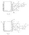
- FIG. 1 shows schematically a coreless induction crucible furnace 1 with a furnace crucible 2 surrounding it Induction coil 3 shown.
- the induction coil 3 is via lines 4.5 and over a frequency converter or oscillating circuit converter 6 connected to a three-phase network 7.
- capacitors are 8.9. provided that with the help of a switch 10 to each other in Row - and in parallel to the induction coil 3 - can be connected to the lines 4,5.
- the capacitors 8.9 can also be reduced by half using switches 11, 12 and lines 13, 14 are connected in such a way that the capacitors 8, 9 in each case electrically parallel to one another, but overall also electrically parallel to the induction coil 3 lie, the switch 10 then being opened again.
- the induction coil 3 also has a center arranged tap 16.
- the induction coil 3 can Lines 4,5 are connected to the resonant circuit converter 6.
- the capacitors 8.9 are connected in series between the lines 4,5.
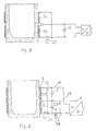
- the switch 23 and the further switches 24, 25 and 29, the switches 23 and 29 being opened via a lock must be, the capacitors 8.9 in parallel with the top half connected to the induction coil 3. In this case, both the capacitance of the capacitor as well as the inductance of the induction coil increases.
- FIG. 3 shows an application example of the invention in which the inductance is doubled in the case of a two-part induction coil 3a, 3b.
- the switch 23 In normal melting operation, the switch 23 is closed and the two coil parts 3a, 3b are thus supplied with the supply voltage. In the state shown, that is to say when switch 23 is not closed, only coil part 3a is switched on. In this case, the operating frequency by the factor 2nd reduced.
- FIG. 4 shows a coreless induction crucible furnace in which partial coils 3a, 3b are provided Connected to the three-phase network 7 via lines 4.5 and via the resonant circuit converter 6 are.
- a capacitor 15 is connected in parallel with the partial coils 3a, 3b.
Landscapes
- Physics & Mathematics (AREA)
- Electromagnetism (AREA)
- General Induction Heating (AREA)
- Furnace Details (AREA)
- Crucibles And Fluidized-Bed Furnaces (AREA)
Description
Claims (8)
- Verfahren zum Betrieb von kernlosen Induktionsschmelz- und/oder -warmhalteöfen,dadurch gekennzeichnet,bei denen im Schmelzbetrieb bei einer Induktionsfrequenz von 100 Hz eine geringe Rührbewegung in der Schmelzeund im Schmelz- oder Warmhaltebetrieb bei einer demgegenüber um maximal 50 % abgesenkten Induktionsfrequenz, die immer 50 Hz ist, eine größere Rührbewegung in der Schmelze resultiert,bei dem mindestens eine Induktionsspule und mindestens ein zu der (den) Induktionsspule(n) elektrisch parallel geschalteter Kondensator vorgesehen ist, der(die) zusammen mit der(den) Induktionsspule(n) einen elektrischen Schwingkreis bildet(n), wobeibeim Übergang von Schmelzbetrieb mit geringerer Rührbewegung in der Schmelze auf Schmelz- oder Warmhaltebetrieb mit größerer Rührbewegung bzw. beim umgekehrten Übergang die Kondensatorkapazität und/oder die im Schwingkreis vorhandene Induktivität erhöht bzw. erniedrigt werden,daß immer mindestens eine Induktionsspule und mindestens zwei im Schmelzbetrieb bei erhöhter Induktionsfrequenz in Reihe geschaltete Kondensatoren vorgesehen sind, die zur Erhöhung der Kondensatorkapazität durch Umschaltung parallel geschaltet werden und/oderdaß immer mindestens ein Kondensator und mindestens zwei im Schmelzbetrieb bei erhöhter Induktionsfrequenz parallel geschaltete, getrennte oder durch Anzapfung einer Induktionsspule hergestellte Teilspulen vorgesehen sind, die zur Erhöhung der Induktivität durch Umschaltung in Reihe oder teilweise spannungslos geschaltet werden.
- Verfahren nach Anspruch 1, dadurch gekennzeichnet, daß bei vollem Ofen bzw. nahezu ganz mit Metallschmelze gefülltem Ofentiegel nur ein Teil der Spulenwindungen, insbesondere derjenige in der Nähe der Schmelzbadoberfläche, an die elektrische Spannungsversorgungseinrichtung des Induktionsofens angeschlossen wird.
- Verfahren nach einem der vorhergehenden Ansprüche, dadurch gekennzeichnet, daß bei mehreren getrennten Induktionsspulenteilen lediglich die obere bzw. die oberen Teilspulen eingeschaltet werden.
- Elektrische Schalteinheit für kernlose Induktionschmelz- und/oder -warmhalteöfen mit einer Induktionsfrequenz im Bereich von Netz- bis Mittelfrequenz, welche eine elektrische Spannungsversorgungseinrichtung mit einem Frequenzumformer bzw. -umrichter (6) sowie eine ein- oder mehrteilige, um einen Ofentiegel herum angeordnete Induktionsspule (3;3a,3b) und mindestens einen innerhalb des elektrischen Leitungsweges (4,5,13,14) zwischen der Induktionsspule (3;3a,3b) und dem Frequenzumformer (6) liegenden Kondensator (8,9;15) aufweist, wobei der (die) Kondensator(en)(8,9,15)zu der (den) Induktionsspule(n)(3,3a,3b) elektrisch parallel geschaltet ist (sind) und zusammen mit dieser(n) einen elektrischen Schwingkreis bildet(n), dessen Eigenfrequenz auf die jeweilige Induktionsfrequenz abgestimmt ist, und wobei innerhalb des genannten Leitungsweges (4,5,13,14) elektrische Schaltelemente (10,11,12;23,24,25,29;26,27,28) vorgesehen sind, mittels derer die Kapazität und/oder die Induktivität des Schwingkreises und damit dessen Eigenfrequenz stufenförmig einstellbar sind, zur Durchführung des Verfahrens nach einem der Ansprüche 1 bis 3,
dadurch gekennzeichnet,
daß im Falle einer einteiligen Induktionsspule (3) mindestens zwei Kondensatoren (8,9) vorgesehen sind und die Schaltelemente (10,11,12;23,24,25,29;26,27,28) derart ausgebildet sind, daß bei deren Betätigung zunächst zueinander in Reihe geschaltete Kondensatoren (8,9) zueinander parallel geschaltet werden können und/oder zunächst parallel geschaltete Induktionsspulen (3a,3b) in Reihe oder teilweise spannungslos geschaltet werden können und umgekehrt. - Schalteinheit nach Anspruch 4, dadurch gekennzeichnet, daß mindestens zwei Schaltelemente 10,11,12;23,24,25,29;26,27,28) mittels einer elektrischen bzw. Elektromechanischen Verriegelung gegeneinander sperrbar sind.
- Schalteinheit nach einem der Ansprüche 4 oder 5, dadurch gekennzeichnet, daß die Induktionsspule(n) (3,3a,3b) mittels wenigstens einer Anzapfung geteilt ist(sind).
- Schalteinheit nach einem der Ansprüche 4 bis 6, dadurch gekennzeichnet, daß der in der Nähe der Schmelzbadoberfläche liegende Teil der Windungen der Induktionsspule(n) (3,3a,3b) mit der Versorgungsspannung beaufschlagt ist.
- Schalteinheit nach einem der Ansprüche 4 bis 7, dadurch gekennzeichnet, daß mindestens zwei elektrisch getrennte Induktionsspulenteile (3a,3b) vorgesehen sind.
Applications Claiming Priority (3)
| Application Number | Priority Date | Filing Date | Title |
|---|---|---|---|
| DE4404412 | 1994-02-11 | ||
| DE4404412 | 1994-02-11 | ||
| PCT/DE1995/000175 WO1995022238A1 (de) | 1994-02-11 | 1995-02-10 | Verfahren zum betrieb von kernlosen induktionsschmelz- and/oder -warmhalteöfen sowie dafür geeignete elektrische schalteinheit |
Publications (2)
| Publication Number | Publication Date |
|---|---|
| EP0744117A1 EP0744117A1 (de) | 1996-11-27 |
| EP0744117B1 true EP0744117B1 (de) | 1998-05-20 |
Family
ID=6510069
Family Applications (1)
| Application Number | Title | Priority Date | Filing Date |
|---|---|---|---|
| EP95910392A Expired - Lifetime EP0744117B1 (de) | 1994-02-11 | 1995-02-10 | Verfahren zum betrieb von kernlosen induktionsschmelz- und/oder -warmhalteöfen sowie dafür geeignete elektrische schalteinheit |
Country Status (5)
| Country | Link |
|---|---|
| US (1) | US5889812A (de) |
| EP (1) | EP0744117B1 (de) |
| AT (1) | ATE166522T1 (de) |
| DE (1) | DE59502256D1 (de) |
| WO (1) | WO1995022238A1 (de) |
Families Citing this family (9)
| Publication number | Priority date | Publication date | Assignee | Title |
|---|---|---|---|---|
| FR2790354B1 (fr) * | 1999-02-26 | 2001-06-15 | Centre Nat Rech Scient | Brassage electromagnetique d'un metal en fusion |
| DE19926198A1 (de) * | 1999-06-09 | 2000-12-14 | Junker Gmbh O | Schaltung und Steuerverfahren für Wechselrichter zur Speisung von Induktionsöfen |
| DE19939778C2 (de) * | 1999-08-21 | 2001-09-13 | Schott Glas | Vorrichtung zum Erschmelzen und/oder Läutern anorganischer Verbindungen |
| MXPA03006084A (es) * | 2001-01-08 | 2003-09-10 | Inductotherm Corp | Horno de induccion con sistema de bobina de eficiencia mejorada. |
| FR2954660B1 (fr) * | 2009-12-18 | 2012-03-09 | Efd Induction Sa | Four a induction de fusion/brassage |
| CN102279019A (zh) * | 2011-06-28 | 2011-12-14 | 华南理工大学 | 一种大功率中频感应炉数据采集与监控装置 |
| EP2704524A1 (de) * | 2012-08-28 | 2014-03-05 | AEG Power Solutions GmbH | Vorrichtung zum Erwärmen mittels elektromagnetischer Induktion, insbesondere Induktionsheizung oder Induktionsofen |
| JP7494487B2 (ja) * | 2020-03-03 | 2024-06-04 | 富士電機株式会社 | 誘導加熱装置 |
| CN113915999B (zh) * | 2021-09-17 | 2024-01-23 | 中冶赛迪工程技术股份有限公司 | 一种中频感应电弧炉及冶炼控制方法 |
Family Cites Families (16)
| Publication number | Priority date | Publication date | Assignee | Title |
|---|---|---|---|---|
| US1286393A (en) * | 1916-12-26 | 1918-12-03 | Hopedale Mfg Co | Feeler-loom. |
| US1852215A (en) * | 1928-10-16 | 1932-04-05 | Ajax Electrothermic Corp | Inductor type furnace |
| US1822539A (en) * | 1929-03-09 | 1931-09-08 | Ajax Electrothermic Corp | Induction electric furnace |
| US1943802A (en) * | 1930-03-18 | 1934-01-16 | Ajax Electrothermic Corp | Electric induction furnace |
| US1940622A (en) * | 1932-02-10 | 1933-12-19 | Ajax Electrothermic Corp | Electric induction furnace method |
| US3314670A (en) * | 1963-11-15 | 1967-04-18 | Inductotherm Corp | Molten metal stirring apparatus |
| SE311201B (de) * | 1964-06-18 | 1969-06-02 | Asea Ab | |
| DK119181B (da) * | 1966-12-21 | 1970-11-23 | Almex Ab | Tegnlæser. |
| US3536983A (en) * | 1967-12-12 | 1970-10-27 | Inductotherm Corp | Frequency multiplier and stirring circuit for an induction furnace |
| US3913005A (en) * | 1974-08-28 | 1975-10-14 | Inductotherm Corp | Frequency multiplier circuit for controlling harmonic currents |
| JPS5139505A (ja) * | 1974-10-01 | 1976-04-02 | Fuji Dempa Kogyo | Yotokakuhanhokoseigyogatajudodenkiro |
| BE857189A (fr) * | 1977-07-27 | 1978-01-27 | Elphiac Sa | Four a induction a creuset |
| GB2200979B (en) * | 1987-02-14 | 1990-08-29 | Inductotherm Europ | Induction melting |
| DE3910777C2 (de) * | 1989-04-04 | 2001-08-09 | Ald Vacuum Techn Ag | Induktionsofen mit einem metallischen Tiegel |
| GB2232832B (en) * | 1989-06-14 | 1993-11-10 | Inductotherm Europ | Induction Melting |
| JPH0636865A (ja) * | 1992-07-16 | 1994-02-10 | Shinko Electric Co Ltd | 2周波電源高周波誘導炉 |
-
1995
- 1995-02-10 US US08/693,147 patent/US5889812A/en not_active Expired - Fee Related
- 1995-02-10 WO PCT/DE1995/000175 patent/WO1995022238A1/de not_active Ceased
- 1995-02-10 AT AT95910392T patent/ATE166522T1/de not_active IP Right Cessation
- 1995-02-10 DE DE59502256T patent/DE59502256D1/de not_active Expired - Fee Related
- 1995-02-10 EP EP95910392A patent/EP0744117B1/de not_active Expired - Lifetime
Also Published As
| Publication number | Publication date |
|---|---|
| DE59502256D1 (de) | 1998-06-25 |
| WO1995022238A1 (de) | 1995-08-17 |
| US5889812A (en) | 1999-03-30 |
| ATE166522T1 (de) | 1998-06-15 |
| EP0744117A1 (de) | 1996-11-27 |
Similar Documents
| Publication | Publication Date | Title |
|---|---|---|
| DE586822C (de) | Verfahren zur Regelung der Badbewegung in Induktionsoefen ohne Eisenkern | |
| DE4112161C2 (de) | Gasentladungseinrichtung | |
| EP0884830B1 (de) | Leistungsversorgungseinheit mit einem pulsdauermodulierten Wechselrichter, insbesondere für einen Röntgengenerator | |
| WO2005060081A1 (de) | Umrichterschaltung mit zwei teilumrichtern | |
| DE202007005779U1 (de) | MF-Plasmaleistungsgenerator | |
| DE69111229T2 (de) | Verfahren und gerät zur oberflächenhärtung von rotationssymmetrischen teilen durch induktionsheizen mittels wenigstens zwei verschiedener frequenzen. | |
| DE4400436A1 (de) | Wechselrichter-Einrichtung | |
| DE102012107122A1 (de) | Wechselrichterschaltung | |
| EP0744117A1 (de) | Verfahren zum betrieb von kernlosen induktionsschmelz- and/oder -warmhalteöfen sowie dafür geeignete elektrische schalteinheit | |
| EP1297613A1 (de) | Schaltnetzteil | |
| DE4330859A1 (de) | Elektronischer Ballast für eine Entladungslampe | |
| EP3297403A1 (de) | Umrichtergespeister lichtbogenofen mit kondensatoranordnung im sekundärkreis | |
| EP0740494A2 (de) | Schaltungsanordnung zum Impulsbetrieb von Entladungslampen | |
| DE4305768C2 (de) | Netzanschlußgerät | |
| DE102007051666A1 (de) | Stromversorgungseinrichtung für Induktionsöfen | |
| DE3312574A1 (de) | Elektronisches vorschaltgeraet fuer leuchtstofflampen | |
| EP1194011B1 (de) | Umrichterschaltung und Verfahren zum Betrieb einer solchen | |
| WO1996028876A1 (de) | Schaltungsanordnung | |
| DE19726161A1 (de) | Verfahren zum Betrieb parallel geschalteter Stromzwischenkreisumrichter zur Speisung eines Asynchronmotor und dazugehörige Schaltungsanordnung | |
| DE756749C (de) | Zwei- oder mehrphasiger kernloser Induktionsofen | |
| EP1243165B1 (de) | Schaltungsanordnung zum betreiben einer gasentladungslampe | |
| EP0487767B1 (de) | Hochfrequenz-Röntgengenerator | |
| DE102006032640B4 (de) | Umrichter, insbesondere zur Erzeugung von Wirkleistung für die induktive Erwärmung und Verfahren zum induktiven Schmelzen und Rühren | |
| DE3614708A1 (de) | Steuerschaltung fuer eine lichtbogenlampe | |
| DE2748136A1 (de) | Kernloser induktions-tiegelofen |
Legal Events
| Date | Code | Title | Description |
|---|---|---|---|
| PUAI | Public reference made under article 153(3) epc to a published international application that has entered the european phase |
Free format text: ORIGINAL CODE: 0009012 |
|
| 17P | Request for examination filed |
Effective date: 19960806 |
|
| AK | Designated contracting states |
Kind code of ref document: A1 Designated state(s): AT BE CH DE FR GB IT LI |
|
| 17Q | First examination report despatched |
Effective date: 19970303 |
|
| GRAG | Despatch of communication of intention to grant |
Free format text: ORIGINAL CODE: EPIDOS AGRA |
|
| GRAG | Despatch of communication of intention to grant |
Free format text: ORIGINAL CODE: EPIDOS AGRA |
|
| GRAH | Despatch of communication of intention to grant a patent |
Free format text: ORIGINAL CODE: EPIDOS IGRA |
|
| GRAH | Despatch of communication of intention to grant a patent |
Free format text: ORIGINAL CODE: EPIDOS IGRA |
|
| GRAA | (expected) grant |
Free format text: ORIGINAL CODE: 0009210 |
|
| AK | Designated contracting states |
Kind code of ref document: B1 Designated state(s): AT BE CH DE FR GB IT LI |
|
| REF | Corresponds to: |
Ref document number: 166522 Country of ref document: AT Date of ref document: 19980615 Kind code of ref document: T |
|
| REG | Reference to a national code |
Ref country code: CH Ref legal event code: EP |
|
| REF | Corresponds to: |
Ref document number: 59502256 Country of ref document: DE Date of ref document: 19980625 |
|
| ITF | It: translation for a ep patent filed | ||
| REG | Reference to a national code |
Ref country code: CH Ref legal event code: NV Representative=s name: E. BLUM & CO. PATENTANWAELTE |
|
| GBT | Gb: translation of ep patent filed (gb section 77(6)(a)/1977) |
Effective date: 19980812 |
|
| ET | Fr: translation filed | ||
| PLBE | No opposition filed within time limit |
Free format text: ORIGINAL CODE: 0009261 |
|
| STAA | Information on the status of an ep patent application or granted ep patent |
Free format text: STATUS: NO OPPOSITION FILED WITHIN TIME LIMIT |
|
| 26N | No opposition filed | ||
| REG | Reference to a national code |
Ref country code: GB Ref legal event code: IF02 |
|
| PGFP | Annual fee paid to national office [announced via postgrant information from national office to epo] |
Ref country code: GB Payment date: 20020122 Year of fee payment: 8 |
|
| PGFP | Annual fee paid to national office [announced via postgrant information from national office to epo] |
Ref country code: CH Payment date: 20020220 Year of fee payment: 8 |
|
| PG25 | Lapsed in a contracting state [announced via postgrant information from national office to epo] |
Ref country code: GB Free format text: LAPSE BECAUSE OF NON-PAYMENT OF DUE FEES Effective date: 20030210 |
|
| PG25 | Lapsed in a contracting state [announced via postgrant information from national office to epo] |
Ref country code: LI Free format text: LAPSE BECAUSE OF NON-PAYMENT OF DUE FEES Effective date: 20030228 Ref country code: CH Free format text: LAPSE BECAUSE OF NON-PAYMENT OF DUE FEES Effective date: 20030228 |
|
| GBPC | Gb: european patent ceased through non-payment of renewal fee | ||
| REG | Reference to a national code |
Ref country code: CH Ref legal event code: PL |
|
| PGFP | Annual fee paid to national office [announced via postgrant information from national office to epo] |
Ref country code: AT Payment date: 20070221 Year of fee payment: 13 |
|
| PGFP | Annual fee paid to national office [announced via postgrant information from national office to epo] |
Ref country code: DE Payment date: 20070228 Year of fee payment: 13 |
|
| PGFP | Annual fee paid to national office [announced via postgrant information from national office to epo] |
Ref country code: BE Payment date: 20070301 Year of fee payment: 13 |
|
| PGFP | Annual fee paid to national office [announced via postgrant information from national office to epo] |
Ref country code: IT Payment date: 20070531 Year of fee payment: 13 |
|
| PGFP | Annual fee paid to national office [announced via postgrant information from national office to epo] |
Ref country code: FR Payment date: 20070216 Year of fee payment: 13 |
|
| BERE | Be: lapsed |
Owner name: OTTO *JUNKER G.M.B.H. Effective date: 20080228 |
|
| PG25 | Lapsed in a contracting state [announced via postgrant information from national office to epo] |
Ref country code: AT Free format text: LAPSE BECAUSE OF NON-PAYMENT OF DUE FEES Effective date: 20080210 |
|
| REG | Reference to a national code |
Ref country code: FR Ref legal event code: ST Effective date: 20081031 |
|
| PG25 | Lapsed in a contracting state [announced via postgrant information from national office to epo] |
Ref country code: DE Free format text: LAPSE BECAUSE OF NON-PAYMENT OF DUE FEES Effective date: 20080902 |
|
| PG25 | Lapsed in a contracting state [announced via postgrant information from national office to epo] |
Ref country code: BE Free format text: LAPSE BECAUSE OF NON-PAYMENT OF DUE FEES Effective date: 20080228 |
|
| PG25 | Lapsed in a contracting state [announced via postgrant information from national office to epo] |
Ref country code: FR Free format text: LAPSE BECAUSE OF NON-PAYMENT OF DUE FEES Effective date: 20080229 |
|
| PG25 | Lapsed in a contracting state [announced via postgrant information from national office to epo] |
Ref country code: IT Free format text: LAPSE BECAUSE OF NON-PAYMENT OF DUE FEES Effective date: 20080210 |