EP0743585B1 - Steuerungssystem für ein lineares Elektromagnetventil - Google Patents
Steuerungssystem für ein lineares Elektromagnetventil Download PDFInfo
- Publication number
- EP0743585B1 EP0743585B1 EP96107113A EP96107113A EP0743585B1 EP 0743585 B1 EP0743585 B1 EP 0743585B1 EP 96107113 A EP96107113 A EP 96107113A EP 96107113 A EP96107113 A EP 96107113A EP 0743585 B1 EP0743585 B1 EP 0743585B1
- Authority
- EP
- European Patent Office
- Prior art keywords
- current value
- linear solenoid
- voltage
- duty ratio
- battery
- Prior art date
- Legal status (The legal status is an assumption and is not a legal conclusion. Google has not performed a legal analysis and makes no representation as to the accuracy of the status listed.)
- Expired - Lifetime
Links
- 238000001514 detection method Methods 0.000 claims description 28
- 230000010354 integration Effects 0.000 description 5
- 230000001105 regulatory effect Effects 0.000 description 4
- 125000004122 cyclic group Chemical group 0.000 description 3
- 238000010586 diagram Methods 0.000 description 3
- 230000002159 abnormal effect Effects 0.000 description 2
- 230000005540 biological transmission Effects 0.000 description 2
- 238000010276 construction Methods 0.000 description 2
- 230000000873 masking effect Effects 0.000 description 2
- 239000003990 capacitor Substances 0.000 description 1
- 230000001276 controlling effect Effects 0.000 description 1
- 230000000694 effects Effects 0.000 description 1
- 238000000034 method Methods 0.000 description 1
- 238000012544 monitoring process Methods 0.000 description 1
- 230000007935 neutral effect Effects 0.000 description 1
- 230000007704 transition Effects 0.000 description 1
Images



Classifications
-
- H—ELECTRICITY
- H01—ELECTRIC ELEMENTS
- H01H—ELECTRIC SWITCHES; RELAYS; SELECTORS; EMERGENCY PROTECTIVE DEVICES
- H01H47/00—Circuit arrangements not adapted to a particular application of the relay and designed to obtain desired operating characteristics or to provide energising current
- H01H47/22—Circuit arrangements not adapted to a particular application of the relay and designed to obtain desired operating characteristics or to provide energising current for supplying energising current for relay coil
- H01H47/32—Energising current supplied by semiconductor device
- H01H47/325—Energising current supplied by semiconductor device by switching regulator
-
- G—PHYSICS
- G05—CONTROLLING; REGULATING
- G05D—SYSTEMS FOR CONTROLLING OR REGULATING NON-ELECTRIC VARIABLES
- G05D16/00—Control of fluid pressure
- G05D16/20—Control of fluid pressure characterised by the use of electric means
- G05D16/2006—Control of fluid pressure characterised by the use of electric means with direct action of electric energy on controlling means
- G05D16/2013—Control of fluid pressure characterised by the use of electric means with direct action of electric energy on controlling means using throttling means as controlling means
Definitions
- the present invention relates to a control system for a linear solenoid valve to be mounted on a vehicle.
- the current value in a linear solenoid valve is detected so that a feedback control for correcting the duty ratio of the power supply to the linear solenoid valve is executed on the basis of the detection result.
- the power source is a battery, which acts as a power supply for other devices, too.
- the voltage may fluctuate with the operations of the air conditioner or the wiper, for example.
- the current value also fluctuates so that the feedback control is performed to attain the target current value. Because of a relatively small control gain, as described above, the fluctuation of the voltage cannot be quickly responded to thereby to cause a delay till the target current value is reached.
- the PWM signal is correspondingly subjected to the feedback control. Because of the relatively small control gain, as described above, the width D 1 of the PWM signal is narrow at the instant of the change in the battery voltage and gradually increases in the order of d 1 ⁇ d 2 ⁇ d 3 ⁇ d 4 ⁇ d 5 . As a result, a current value i 1 once drops to a current value i 2 at the transition time and then gradually restores its original value.
- the linear solenoid valve is used for generating the line pressure of an automatic transmission, the line pressure may temporarily be over or below the target value.
- JP-A-7-229 576 relates to a controller for current control type solenoid valve.
- a controller for current control type solenoid valve On the basis of a change DELTAVB of the output voltage VB of a battery detected by an output voltage change detecting means 110, an integration constant KI reprinting a feedback gain and a proportional constant KP are changed.
- an output such as feedback is changed according to the reduction of the output voltage VB of the battery even in sudden increase of the output current of the battery such as in turning on of a headlight and in energizing to a heater in a vehicle, so that a value detected by a current detecting means when a driving current of a current control type solenoid valve is cut off because of a change in the output voltage of the battery in the vehicle is previously determined as an offset value by an offset value determining means.
- An actual driving current calculating means finds an actual driving current by subtracting the off set value from a detection value detected by the current detecting means.
- FR-A-2 648 584 relates to a system for regulating the mean current flowing through the load of an electric remote control device. It discloses a system for regulating the mean current flowing through a load, particularly an electric device controlling the phenomenon to be regulated, from initial variable control information, a DC voltage source being provided for supplying this load, comprising: a measuring device for permanently measuring the value of the variable information; a determination device for causing a mean theoretical current value to be applied to the load to correspond to each value of the information: a further measuring device for measuring the real DC voltage supplied by the supply voltage source; a computing device for computing, from the determined value of the mean theoretical current and the measured value of the DC supply voltage, a theoretical value of the cyclic ratio of a pre-determined fixed frequency square wave voltage signal; a generator for generating a fixed frequency square wave voltage signal having the computed cyclic ratio, this signal being applied to the load; another measuring device for measuring the real mean current flowing through the load; a comparator for comparing the values of the real and theoretical mean current
- the present invention has an object to solve the above-specified problems and to provide a control system for a linear solenoid valve, which is enabled to achieve a target oil pressure level, when a battery voltage fluctuates, by suppressing the fluctuation of a current value to be fed to the linear solenoid valve.
- an electronic control unit 1 receives a signal from a throttle sensor 11 so that the throttle opening is decided in a throttle opening decision unit 2, and the decision result is sent to a linear solenoid current value setting unit (as will be shortly called the "current value setting unit") 4.
- This current value setting unit 4 sets a linear solenoid current value for generating a line pressure of the A/T, as corresponding to a predetermined throttle opening.
- the current value, as set in the current value setting unit 4 is outputted to a feed forward setting unit 5 and a feedback correction unit 6 individually.
- the output of the feedback correction unit 6 is inputted to a voltage correction unit 7, the output of which is inputted to a solenoid driver 9 to control the current of the linear solenoid of a linear solenoid valve 23.
- the electronic control unit 1 receives the signal from the throttle sensor 11 to control the current to the linear solenoid 12 of the linear solenoid valve 23 so as to generate the oil pressure of the automatic transmission, as corresponding to the throttle opening.
- the electronic control unit 1 is provided with a microcomputer 3 including: the current value setting unit 4 for receiving the signal from the throttle opening decision unit 2; the feed forward setting unit 5 for outputting a PWM (Pulse Width Modulation) signal; the feedback correction unit 6; and the voltage correction unit 7. Further provided are: the solenoid driver 9 for driving the linear solenoid 12 of the linear solenoid valve 23; a current monitor unit (or current monitoring resistor) 10a; and a solenoid current monitor 10b.
- reference characters R 1 to R 13 designate resistors; letters NOT a negative logic NOT circuit; characters T r1 to T r3 transistors; characters C 1 to C 4 capacitors; and characters D 1 to D 3 diodes.
- the diode D 1 receives the surge inverse electromotive force by the linear solenoid 12 and is given a function to prevent the transistor T r3 from being broken by the influence of the inverse electromotive force. Further provided is an IG voltage monitor 8 which divides the voltage of a battery B by the resistors R 12 and R 13 so that the divided voltage is inputted to the microcomputer 3.
- reference letters Pr designate a command throttle pressure (or target oil pressure level); letters ir a command current; letters Kpred a feed forward gain; letters Kp a proportional gain; letters KI an integration gain; letters Vbattery a battery voltage; letters Vig the voltage level of the battery; letters Vo a reference voltage (12 V); letters Vduty a duty ratio after the voltage correction; letters Ve an inverse electromotive voltage of the solenoid; V STH a solenoid terminal voltage; letters Ls an inductance of the solenoid; letter R a resistance of the solenoid; letters I STH a solenoid current; letters I STHF a current value of the solenoid; letters ie the difference between the command current ir and the current value I STHF of the solenoid; and letters Rf a current detection resistor.
- characters S/D designate an analog/digital converter
- letters PWM driver designate a PWM driver.
- reference numeral 81 designates means for setting a linear solenoid current value corresponding to the command throttle pressure (as will be shortly called the "current value setting means"); numeral 82 feed forward setting means; and numeral 83 a proportional feedback correction unit for outputted a corrected duty ratio corresponding to the product, as calculated by multiplying the difference ie between the command current ir and the current value I STHF of the solenoid by the proportional gain Kp.
- Numeral 84 designates an integration feedback correction unit for integrating the difference ie to output a corrected duty ratio corresponding to the product, as calculated by multiplying the integrated difference by the integration gain KI.
- Numeral 85 designates feedback correction means, as composed of the proportional feedback correction unit 83 and the integration feedback correction unit 84.
- Numeral 86 designates voltage correction means, and numeral 87 designates duty ratio setting means, as composed of the feedback correction means 85 and the voltage correction means 86.
- Numeral 89 designates voltage level detection means having an A/D converter 88 for detecting the battery voltage;
- numeral 90 power supply means composed of a PWM driver (300 Hz);
- numeral 91 a linear solenoid valve;
- numeral 94 current value detection means composed of a current detection resistor 92 and an A/D converter 93.
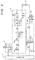
- This hydraulic circuit is equipped with: the linear solenoid valve 23 having the linear solenoid 12; a pump 36; a strainer 37; a primary regulator valve 52 having a main spool 52a, a sub-spool 52b, a plug 52c, a control chamber e, a feedback port f, a line pressure port p 2 , a secondary regulator valve port h and a drain port EX; a throttle valve 53; a secondary regulator valve 55; a solenoid relay valve 58; a cutback valve 59; a solenoid regulator valve 73; and a pressure relief valve 75.
- the primary regulator valve 52 is equipped with the control chamber e for regulating the line pressure in a lower direction and is made to communicate with the control pressure from the linear solenoid valve 23.
- the linear solenoid valve 23 is control to feed the control pressure from the linear solenoid valve 23 to the control chamber e at the shifting time from a neutral range N to a drive range D or a reverse range R.
- the control pressure from the linear solenoid valve 23 is fed through the solenoid relay valve 58 to the control chamber e.
- the primary regulator valve 52 is constructed such that a bias force, as based upon the throttle pressure or the like, is applied to one end of the main spool 52a whereas a feedback pressure from the line pressure port p 2 is applied to the other end and such that a control pressure from the linear solenoid valve 23 is applied to the step portion.
- the primary regulator valve 52 is equipped with the line pressure port p 2 , the drain port EX and the secondary regulator valve port h communicating with the secondary regulator valve 55.
Landscapes
- Physics & Mathematics (AREA)
- Fluid Mechanics (AREA)
- Engineering & Computer Science (AREA)
- General Physics & Mathematics (AREA)
- Automation & Control Theory (AREA)
- Power Engineering (AREA)
- Magnetically Actuated Valves (AREA)
- Servomotors (AREA)
Claims (4)
- Steuerungssystem für ein lineares Elektromagnetventil mit: einem linearen Elektromagnetventil (23) zum Ausgeben eines Öldrucks entsprechend einem einer linearen Magnetspule (12) zuzuführenden Stromwert; einer Stromwertermittlungseinrichtung (10) zum Ermitteln des der linearen Magnetspule des linearen Elektromagnetventils zugeführten Stromwerts; einer Spannungspegelermittlungseinrichtung (8) zum Ermitteln des Spannungspegels einer Batterie; einer Stromwertstelleinrichtung (4) zum Stellen eines Soll-Stromwertes entsprechend einer Soll-Öldruckhöhe; einer Tastverhältnisstelleinrichtung (3a) zum Stellen eines Tastverhältnisses, um die Batteriespannung an die lineare Magnetspule (12) auf der Grundlagen von Signalen anzulegen, die von der Stromwertermittlungseinrichtung (10), der Spannungspegelermittlungseinrichtung (8) und der Stromwertstelleinrichtung (4) kommen; und einer Stromzuführungseinrichtung (9) zum Anlegen der Batteriespannung an die lineare Magnetspule (12) mit einem vorbestimmten Zyklus entsprechend dem von der Tastverhältnisstelleinrichtung (3a) gestellten Tastverhältnis,
wobei die Tastverhältnisstelleinrichtung (3a) aufweist: eine Rückkopplungskorrektureinrichtung (6) zur Durchführung einer Rückkopplungskorrektur des Tastverhältnisses entsprechend der Differenz zwischen dem von der Stromwertermittlungseinrichtung (10) ermittelten Stromwert und dem von der Stromwertstelleinrichtung (4) gestellten Soll-Stromwert, so daß der der linearen Magnetspule (12) zuzuführende Stromwert sich dem Soll-Stromwert nähern kann; und einer Spannungskorrektureinrichtung (7) zum weiteren Korrigieren des von der Rückkopplungskorrektureinrichtung (6) korrigierten Tastverhältnisses auf der Grundlage des von der Spannungspegelermittlungseinrichtung (8) ermittelten Spannungspegels der Batterie;
dadurch gekennzeichnet, daß die Spannungspegelermittlungseinrichtung (8) die Batteriespannung synchron mit dem vorbestimmten Zyklus ermittelt, für den die Stromzuführungseinrichtung (9) die Batteriespannung der linearen Magnetspule (12) zuführt. - Steuerungssystem für ein lineares Elektromagnetventil nach Anspruch 1,
wobei die Spannungskorrektureinrichtung (7) das Tastverhältnis entsprechend dem Verhältnis (Vig/Vo) des von der Spannungspegelermittlungseinrichtung (8) ermittelten Spannungspegels der Batterie zur Referenzspannung (Vo) korrigiert. - Steuerungssystem für ein lineares Elektromagnetventil nach Anspruch 1 oder 2,
wobei die Spannungskorrektureinrichtung (7) das Tastverhältnis nicht korrigiert, wenn der von der Spannungspegelermittlungseinrichtung (8) ermittelte Spannungspegel der Batterie, außerhalb eines vorbestimmten Bereichs ist. - Steuerungssystem für ein lineares Elektromagnetventil nach einem der Ansprüche 1 bis 3,
wobei die Tastverhältnisstelleinrichtung (3a) ferner eine Vorwärtskopplungsstelleinrichtung (5) zum Stellen des Tastverhältnisses entsprechend dem von der Stromwertstelleinrichtung (4) gestellten Soll-Stromwert aufweist und
wobei die Rückkopplungskorrektureinrichtung (6) das von der Vorwärtskopplungsstelleinrichtung (5) gestellte Tastverhältnis korrigiert.
Applications Claiming Priority (3)
| Application Number | Priority Date | Filing Date | Title |
|---|---|---|---|
| JP12145495 | 1995-05-19 | ||
| JP7121454A JP2854538B2 (ja) | 1995-05-19 | 1995-05-19 | リニアソレノイド弁の制御装置 |
| JP121454/95 | 1995-05-19 |
Publications (2)
| Publication Number | Publication Date |
|---|---|
| EP0743585A1 EP0743585A1 (de) | 1996-11-20 |
| EP0743585B1 true EP0743585B1 (de) | 2002-08-14 |
Family
ID=14811537
Family Applications (1)
| Application Number | Title | Priority Date | Filing Date |
|---|---|---|---|
| EP96107113A Expired - Lifetime EP0743585B1 (de) | 1995-05-19 | 1996-05-06 | Steuerungssystem für ein lineares Elektromagnetventil |
Country Status (4)
| Country | Link |
|---|---|
| US (1) | US5790364A (de) |
| EP (1) | EP0743585B1 (de) |
| JP (1) | JP2854538B2 (de) |
| DE (1) | DE69622921T2 (de) |
Families Citing this family (22)
| Publication number | Priority date | Publication date | Assignee | Title |
|---|---|---|---|---|
| JP3800361B2 (ja) * | 1996-09-20 | 2006-07-26 | 株式会社日立製作所 | サスペンション制御装置 |
| JP2000179667A (ja) * | 1998-12-18 | 2000-06-27 | Hitachi Ltd | 自動車用油圧制御装置及び制御方法 |
| US6477026B1 (en) | 2000-07-05 | 2002-11-05 | Case Corporation | Single package solenoid having control circuit |
| JP4008683B2 (ja) * | 2001-09-26 | 2007-11-14 | ジヤトコ株式会社 | 自動変速機の制御装置 |
| US6671158B1 (en) * | 2001-11-05 | 2003-12-30 | Deltrol Controls | Pulse width modulated solenoid |
| US7126805B2 (en) * | 2003-04-10 | 2006-10-24 | Honda Motor Co., Ltd. | Solenoid driving device |
| US8746812B2 (en) * | 2004-10-08 | 2014-06-10 | Marcia Albright | Brake control unit |
| ES2363717T3 (es) * | 2005-07-29 | 2011-08-12 | Graco Minnesota Inc. | Bomba alternativa con válvula de aire monitorizada electrónicamente que tiene una batería y monitorización electrónica por solenoide. |
| US7872845B2 (en) * | 2007-03-30 | 2011-01-18 | Infineon Technologies Ag | Control system |
| KR100913912B1 (ko) * | 2007-05-23 | 2009-08-26 | 주식회사 만도 | 차량의 에어 서스펜션 시스템에서의 솔레노이드 밸브의 제어 장치 및 방법 |
| DE102007032178B3 (de) * | 2007-07-10 | 2008-12-11 | Continental Automotive Gmbh | Kraftfahrzeug-Kontrollvorrichtung und zugehöriges Verfahren zur Regelung des elektrischen Stroms eines Aktuators |
| DE102007057502A1 (de) * | 2007-11-29 | 2009-06-04 | Robert Bosch Gmbh | Regelvorrichtung und -verfahren zum Regeln eines mittleren Stromes durch eine induktive Last |
| US7746620B2 (en) * | 2008-02-22 | 2010-06-29 | Baxter International Inc. | Medical fluid machine having solenoid control system with temperature compensation |
| US7782590B2 (en) * | 2008-02-22 | 2010-08-24 | Baxter International Inc. | Medical fluid machine having solenoid control system with reduced hold current |
| US8109256B2 (en) * | 2008-11-17 | 2012-02-07 | GM Global Technology Operations LLC | Solenoid current control with direct forward prediction and iterative backward state estimation |
| JP5359476B2 (ja) * | 2009-04-06 | 2013-12-04 | トヨタ自動車株式会社 | ソレノイド制御装置 |
| US9435459B2 (en) * | 2009-06-05 | 2016-09-06 | Baxter International Inc. | Solenoid pinch valve apparatus and method for medical fluid applications having reduced noise production |
| CN102200558A (zh) * | 2010-03-25 | 2011-09-28 | 鸿富锦精密工业(深圳)有限公司 | 开/关机检测电路 |
| KR20130086423A (ko) * | 2012-01-25 | 2013-08-02 | 삼성전자주식회사 | 데이터 스트로브 신호의 듀티비 보정 방법 |
| JP6118621B2 (ja) * | 2013-04-08 | 2017-04-19 | 日立オートモティブシステムズ株式会社 | 車両用電子制御装置 |
| US20150167589A1 (en) * | 2013-12-13 | 2015-06-18 | Hyundai Motor Company | Method and apparatus for controlling high pressure shut-off valve |
| DE112016001920B4 (de) * | 2015-07-21 | 2025-09-11 | Aisin Corporation | Steuervorrichtung zum elektrischen Steuern eines Solenoidventils |
Family Cites Families (13)
| Publication number | Priority date | Publication date | Assignee | Title |
|---|---|---|---|---|
| JPS6056948B2 (ja) * | 1977-02-08 | 1985-12-12 | 株式会社日本自動車部品総合研究所 | 電磁弁駆動装置 |
| JPS6056948A (ja) * | 1983-09-07 | 1985-04-02 | Sumitomo Chem Co Ltd | オキシム誘導体、その製造法およびそれを有効成分として含有する殺虫剤 |
| JPS6217473U (de) * | 1985-07-18 | 1987-02-02 | ||
| US4878147A (en) * | 1987-08-05 | 1989-10-31 | Kabushiki Kaisha Toshiba | Electromagnetic coil drive device |
| DE3908192A1 (de) * | 1989-03-14 | 1990-09-20 | Licentia Gmbh | Elektronische schuetzansteuerung |
| US4898361A (en) * | 1989-04-28 | 1990-02-06 | General Motors Corporation | Submodulation of a pulse-width-modulated solenoid control valve |
| FR2648584B1 (fr) * | 1989-06-16 | 1991-10-11 | Rexroth Sigma | Procede et systeme de regulation du courant moyen traversant une charge, et dispositif de telecommande electrique du type manipulateur en faisant application |
| JP2798457B2 (ja) * | 1989-12-28 | 1998-09-17 | アイシン・エィ・ダブリュ株式会社 | 電子制御式自動変速機 |
| DE4109233A1 (de) * | 1991-03-21 | 1992-09-24 | Rexroth Mannesmann Gmbh | Digitale ansteuerelektronik mit pulsweitenmoduliertem (pwm)-ausgangssignal zum ansteuern elektrischer stellglieder eines hydraulischen systems |
| DE4140586C2 (de) * | 1991-12-10 | 1995-12-21 | Clark Equipment Co N D Ges D S | Verfahren und Steuereinrichtung zur Steuerung des Stroms durch eine Magnetspule |
| FR2696253B1 (fr) * | 1992-09-28 | 1994-12-09 | Siemens Automotive Sa | Procédé et dispositif de régulation du courant moyen dans une charge selfique commandée en rapport cyclique d'ouverture variable. |
| DE4329917A1 (de) * | 1993-09-04 | 1995-03-09 | Bosch Gmbh Robert | Schaltungsanordnung zur getakteten Versorgung eines elektromagnetischen Verbrauchers |
| JP3017635B2 (ja) * | 1994-02-17 | 2000-03-13 | トヨタ自動車株式会社 | 電流制御型電磁弁の制御装置 |
-
1995
- 1995-05-19 JP JP7121454A patent/JP2854538B2/ja not_active Expired - Fee Related
-
1996
- 1996-05-06 EP EP96107113A patent/EP0743585B1/de not_active Expired - Lifetime
- 1996-05-06 DE DE69622921T patent/DE69622921T2/de not_active Expired - Lifetime
- 1996-05-16 US US08/648,718 patent/US5790364A/en not_active Expired - Lifetime
Also Published As
| Publication number | Publication date |
|---|---|
| DE69622921T2 (de) | 2003-01-02 |
| DE69622921D1 (de) | 2002-09-19 |
| EP0743585A1 (de) | 1996-11-20 |
| JPH08312830A (ja) | 1996-11-26 |
| JP2854538B2 (ja) | 1999-02-03 |
| US5790364A (en) | 1998-08-04 |
Similar Documents
| Publication | Publication Date | Title |
|---|---|---|
| EP0743585B1 (de) | Steuerungssystem für ein lineares Elektromagnetventil | |
| US5752209A (en) | Electric power steering apparatus | |
| US5951616A (en) | Current control system for linear solenoid | |
| US10451180B2 (en) | Control device | |
| US8392077B1 (en) | Transmission control apparatus | |
| EP2320547B1 (de) | Stromgesteuertes Halbleiterbauelement und Steuereinheit, die dieses einsetzt | |
| CA2042389A1 (en) | Dual current sensing driver circuit | |
| US5773981A (en) | Method of detecting linear solenoid inter-terminal short of electronic control type automatic transmission | |
| US7026796B2 (en) | Booster circuit and method for controlling the same | |
| US11329565B2 (en) | Feed-forward control for regulating a DC-DC voltage converter | |
| US5094333A (en) | Current control device for an automotive electromagnetic clutch | |
| CN101688495B (zh) | 用于适配调节流量调节阀的电阻值的方法 | |
| US4745514A (en) | Load current control device | |
| US10615690B2 (en) | Feed-forward controlled DC-DC voltage converter and method for regulating a feed-forward controlled DC-DC voltage converter | |
| US5335565A (en) | Electronic control type automatic speed changer | |
| US4975628A (en) | Closed-loop PWM current control for a vehicle transmission force motor | |
| US10056832B2 (en) | Load driving control apparatus | |
| US5416665A (en) | Vehicle electromagnetic clutch control device | |
| US6199002B1 (en) | Control method and apparatus using control gain variable with estimated operation of control object | |
| US5365437A (en) | Internal line hydraulic fluid pressure transmission recalibration unit | |
| US20230224197A1 (en) | Circuit and method for determining a dither amplitude | |
| US6262556B1 (en) | Force motor current control for an electronically controlled automatic transmission | |
| JPH08254280A (ja) | ソレノイド駆動装置 | |
| EP0810500B1 (de) | Steuerungsschaltung für proportionales Steuerventil, insbesondere zum Gebrauch bei Kraftfahrzeugen | |
| JPH11327602A (ja) | 誘導性負荷の駆動装置 |
Legal Events
| Date | Code | Title | Description |
|---|---|---|---|
| PUAI | Public reference made under article 153(3) epc to a published international application that has entered the european phase |
Free format text: ORIGINAL CODE: 0009012 |
|
| AK | Designated contracting states |
Kind code of ref document: A1 Designated state(s): DE GB |
|
| 17P | Request for examination filed |
Effective date: 19961119 |
|
| 17Q | First examination report despatched |
Effective date: 19990323 |
|
| GRAG | Despatch of communication of intention to grant |
Free format text: ORIGINAL CODE: EPIDOS AGRA |
|
| GRAG | Despatch of communication of intention to grant |
Free format text: ORIGINAL CODE: EPIDOS AGRA |
|
| GRAG | Despatch of communication of intention to grant |
Free format text: ORIGINAL CODE: EPIDOS AGRA |
|
| GRAH | Despatch of communication of intention to grant a patent |
Free format text: ORIGINAL CODE: EPIDOS IGRA |
|
| GRAH | Despatch of communication of intention to grant a patent |
Free format text: ORIGINAL CODE: EPIDOS IGRA |
|
| GRAA | (expected) grant |
Free format text: ORIGINAL CODE: 0009210 |
|
| AK | Designated contracting states |
Kind code of ref document: B1 Designated state(s): DE GB |
|
| REG | Reference to a national code |
Ref country code: GB Ref legal event code: FG4D |
|
| REF | Corresponds to: |
Ref document number: 69622921 Country of ref document: DE Date of ref document: 20020919 |
|
| PG25 | Lapsed in a contracting state [announced via postgrant information from national office to epo] |
Ref country code: GB Free format text: LAPSE BECAUSE OF NON-PAYMENT OF DUE FEES Effective date: 20030506 |
|
| PLBE | No opposition filed within time limit |
Free format text: ORIGINAL CODE: 0009261 |
|
| STAA | Information on the status of an ep patent application or granted ep patent |
Free format text: STATUS: NO OPPOSITION FILED WITHIN TIME LIMIT |
|
| 26N | No opposition filed |
Effective date: 20030515 |
|
| GBPC | Gb: european patent ceased through non-payment of renewal fee |
Effective date: 20030506 |
|
| PGFP | Annual fee paid to national office [announced via postgrant information from national office to epo] |
Ref country code: DE Payment date: 20140430 Year of fee payment: 19 |
|
| REG | Reference to a national code |
Ref country code: DE Ref legal event code: R119 Ref document number: 69622921 Country of ref document: DE |
|
| PG25 | Lapsed in a contracting state [announced via postgrant information from national office to epo] |
Ref country code: DE Free format text: LAPSE BECAUSE OF NON-PAYMENT OF DUE FEES Effective date: 20151201 |