EP0741867B1 - Verfahren und vorrichtung zur trägergasflussratenregelung in einem chromatographen - Google Patents
Verfahren und vorrichtung zur trägergasflussratenregelung in einem chromatographen Download PDFInfo
- Publication number
- EP0741867B1 EP0741867B1 EP95933372A EP95933372A EP0741867B1 EP 0741867 B1 EP0741867 B1 EP 0741867B1 EP 95933372 A EP95933372 A EP 95933372A EP 95933372 A EP95933372 A EP 95933372A EP 0741867 B1 EP0741867 B1 EP 0741867B1
- Authority
- EP
- European Patent Office
- Prior art keywords
- flow rate
- carrier gas
- column
- inlet pressure
- gas
- Prior art date
- Legal status (The legal status is an assumption and is not a legal conclusion. Google has not performed a legal analysis and makes no representation as to the accuracy of the status listed.)
- Expired - Lifetime
Links
- 239000012159 carrier gas Substances 0.000 title claims description 45
- 239000007789 gas Substances 0.000 title claims description 35
- 238000000034 method Methods 0.000 title claims description 24
- 238000004458 analytical method Methods 0.000 claims description 12
- 238000011144 upstream manufacturing Methods 0.000 claims description 7
- 238000010926 purge Methods 0.000 claims description 4
- 238000002347 injection Methods 0.000 claims description 2
- 239000007924 injection Substances 0.000 claims description 2
- 238000001514 detection method Methods 0.000 claims 4
- 238000012986 modification Methods 0.000 claims 1
- 230000004048 modification Effects 0.000 claims 1
- 238000006467 substitution reaction Methods 0.000 claims 1
- 230000001276 controlling effect Effects 0.000 description 9
- 239000012530 fluid Substances 0.000 description 5
- 230000004907 flux Effects 0.000 description 5
- IJGRMHOSHXDMSA-UHFFFAOYSA-N Atomic nitrogen Chemical compound N#N IJGRMHOSHXDMSA-UHFFFAOYSA-N 0.000 description 2
- VYPSYNLAJGMNEJ-UHFFFAOYSA-N Silicium dioxide Chemical compound O=[Si]=O VYPSYNLAJGMNEJ-UHFFFAOYSA-N 0.000 description 2
- 238000004587 chromatography analysis Methods 0.000 description 2
- 230000000875 corresponding effect Effects 0.000 description 2
- 230000007423 decrease Effects 0.000 description 2
- 239000006185 dispersion Substances 0.000 description 2
- 238000004817 gas chromatography Methods 0.000 description 2
- 239000001307 helium Substances 0.000 description 2
- 229910052734 helium Inorganic materials 0.000 description 2
- SWQJXJOGLNCZEY-UHFFFAOYSA-N helium atom Chemical compound [He] SWQJXJOGLNCZEY-UHFFFAOYSA-N 0.000 description 2
- 238000005406 washing Methods 0.000 description 2
- 101100256358 Caenorhabditis elegans seb-2 gene Proteins 0.000 description 1
- 230000005526 G1 to G0 transition Effects 0.000 description 1
- UFHFLCQGNIYNRP-UHFFFAOYSA-N Hydrogen Chemical compound [H][H] UFHFLCQGNIYNRP-UHFFFAOYSA-N 0.000 description 1
- 230000033228 biological regulation Effects 0.000 description 1
- 238000003965 capillary gas chromatography Methods 0.000 description 1
- 238000006243 chemical reaction Methods 0.000 description 1
- 230000000295 complement effect Effects 0.000 description 1
- 230000002596 correlated effect Effects 0.000 description 1
- 230000001419 dependent effect Effects 0.000 description 1
- 238000010586 diagram Methods 0.000 description 1
- 230000000694 effects Effects 0.000 description 1
- 238000009472 formulation Methods 0.000 description 1
- 239000001257 hydrogen Substances 0.000 description 1
- 229910052739 hydrogen Inorganic materials 0.000 description 1
- 239000000203 mixture Substances 0.000 description 1
- 229910052757 nitrogen Inorganic materials 0.000 description 1
- 230000001105 regulatory effect Effects 0.000 description 1
- 238000000926 separation method Methods 0.000 description 1
- 239000000377 silicon dioxide Substances 0.000 description 1
- 239000000243 solution Substances 0.000 description 1
Images

Classifications
-
- G—PHYSICS
- G01—MEASURING; TESTING
- G01N—INVESTIGATING OR ANALYSING MATERIALS BY DETERMINING THEIR CHEMICAL OR PHYSICAL PROPERTIES
- G01N30/00—Investigating or analysing materials by separation into components using adsorption, absorption or similar phenomena or using ion-exchange, e.g. chromatography or field flow fractionation
- G01N30/02—Column chromatography
- G01N30/26—Conditioning of the fluid carrier; Flow patterns
- G01N30/28—Control of physical parameters of the fluid carrier
- G01N30/32—Control of physical parameters of the fluid carrier of pressure or speed
-
- G—PHYSICS
- G01—MEASURING; TESTING
- G01N—INVESTIGATING OR ANALYSING MATERIALS BY DETERMINING THEIR CHEMICAL OR PHYSICAL PROPERTIES
- G01N30/00—Investigating or analysing materials by separation into components using adsorption, absorption or similar phenomena or using ion-exchange, e.g. chromatography or field flow fractionation
- G01N30/02—Column chromatography
- G01N2030/022—Column chromatography characterised by the kind of separation mechanism
- G01N2030/025—Gas chromatography
-
- G—PHYSICS
- G01—MEASURING; TESTING
- G01N—INVESTIGATING OR ANALYSING MATERIALS BY DETERMINING THEIR CHEMICAL OR PHYSICAL PROPERTIES
- G01N30/00—Investigating or analysing materials by separation into components using adsorption, absorption or similar phenomena or using ion-exchange, e.g. chromatography or field flow fractionation
- G01N30/02—Column chromatography
- G01N30/26—Conditioning of the fluid carrier; Flow patterns
- G01N30/28—Control of physical parameters of the fluid carrier
- G01N30/30—Control of physical parameters of the fluid carrier of temperature
- G01N2030/3084—Control of physical parameters of the fluid carrier of temperature ovens
-
- G—PHYSICS
- G01—MEASURING; TESTING
- G01N—INVESTIGATING OR ANALYSING MATERIALS BY DETERMINING THEIR CHEMICAL OR PHYSICAL PROPERTIES
- G01N30/00—Investigating or analysing materials by separation into components using adsorption, absorption or similar phenomena or using ion-exchange, e.g. chromatography or field flow fractionation
- G01N30/02—Column chromatography
- G01N30/26—Conditioning of the fluid carrier; Flow patterns
- G01N30/28—Control of physical parameters of the fluid carrier
- G01N30/32—Control of physical parameters of the fluid carrier of pressure or speed
- G01N2030/324—Control of physical parameters of the fluid carrier of pressure or speed speed, flow rate
-
- G—PHYSICS
- G01—MEASURING; TESTING
- G01N—INVESTIGATING OR ANALYSING MATERIALS BY DETERMINING THEIR CHEMICAL OR PHYSICAL PROPERTIES
- G01N30/00—Investigating or analysing materials by separation into components using adsorption, absorption or similar phenomena or using ion-exchange, e.g. chromatography or field flow fractionation
- G01N30/02—Column chromatography
- G01N30/86—Signal analysis
- G01N30/8658—Optimising operation parameters
Definitions
- the present invention relates to a method and a device for controlling pressure and flow rate of carrier gas in apparatus for gas chromatographic analysis with capillary column.
- Feeding carrier gas with constant flow rate does not present a solution to the problem when the column operates in association with injectors of the split/splitless type, certainly well known, which present different exit lines open to the atmosphere. Maintaining a constant carrier flow at the entrance of the injector does not guarantee a constant flow through the column because the fluid resistance in the column
- EP-A-396884 Hewlett Packard Company (corresponding to USA patent N.4994096) relates to a method and apparatus for controlling carrier gas flow rate through control of inlet pressure taking temperature into account.
- This control is accomplished by applying equation derived from the above mentioned Poiseulle's equation, and by computer processing the value of inlet pressure each time required in order to get the desired flowrate.
- equation derived from the above mentioned Poiseulle's equation
- gas data viscosity at column temperature and density in standard conditions
- Purpose of the present invention is to provide a method and device for controlling the flow of carrier gas, by controlling the pressure feeding in apparatuses for gas chromatography analysis with capillary column, which allow eliminating or at least reducing substantially errors entered because of differences between real and ideal conditions in the chromatographic column, besides the ones that may have been entered by operator.
- the method and apparatus according to the present invention require no more entering system data via computer keyboard, but a previous calculation of the constant representing them in the Poiseulle's equation, performed detecting values of the variables present in that equation (flow, pressure and temperature) in a stabilized condition of flow through a column.
- the invention is related to a method for controlling the carrier gas flow rate through a gas chromatographic apparatus according to what stated in claim 1.
- the flow detector (as well as the inlet pressure detector) should be positioned upstream of the column and therefore of the injector, and as the present flow detectors detect in reality a mass flow (expressed in terms of volumetric flow in preset (standard) conditions of pressure and temperature), calculation of constant, which generally comprises both system data and gas data, can be performed as follows.
- K F st T 1,7 pi 2 -po 2
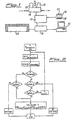
- the device outlined comprises, on the line of carrier gas feeding, a valve 11 electronically controlled to control the feeding pressure, a pressure detector 12 and a mass flow rate detector 13, all operating under control of a local electronic circuit 14, specifically of analog type, that sees to reading pressure and flow signals from detectors 12 and 13 and to generating a command signal for the valve, on the basis of effective and set values.
- Circuit 14 is on turn connected with central control circuit 15 that performs the analog/diigital conversion of the pressure set and all other calculations required. Pressure and flow rate data, both effective and set, are shown in panel 16, bearing an indicator 17 to visualize pressure and flow values, as well as a keyboard 18 for setting desired data by operator. Circuit 15 is connected to CPU 19 to detect, from oven 20, the temperature signal necessary to perform calculations, as well as to allow in case a remote control, through personal computer 21:
- K F st . T 1,7 pi 2 -po 2 is performed detecting pressure and flow values 12 and 13 in stabilized conditions of carrier gas feeding and of thermic regulation of oven 20.
- control circuit 15 commands a pressure value, receives pressure and flow rate signals from circuit 14, temperature signals from CPU 19 and performs calculation of constant K, which is then stored and utilized for calculating and controlling flow through pressure, in all subsequent analyses with same column and same carrier.
- a flow rate or a variation of flow in time
- the gas chromatograph utilizes an injector of split-splitless type
- the calculation of constant K is performed closing the splitting line and the purge line of septum, so that all the carrier introduced streams through the column.
- the opening of the splitting line and of the purge line determines an increase in the fed carrier flow rate, in equal conditions of pressure, whereas (in equal other contitions) the flow fed at the column downstream of splitting line remains unvaried.
- the injector utilized is of on column type, then it will be necessary all the flow rate of the carrier gas fed for calculating costant should stream through the injector and the column, while an occasional dispersion of carrier from the injector introduction, during injection, does not influence correct determination of flow fed at column on the basis of pressure control.
- figure 2 is depicted a flowchart that can be utilized for calculating constant K through the automatic setting of pressure.
- the system starts setting a pressure of 10kPa and increasing it by 10kPa steps till flow detector 13 detects a flow rate sufficiently high to be measured with accuracy.
- setting n 1, at step 1 it is set at step 2 the first pressure value desired (10kPa) and at step 3 there are detected the actual pressure, temperature and flow rate values.
- Actual pressure is controlled at step 4 so as to verify its being inferior to a preset limit (for instance 20kPa), and this being verified, at step 5 the flow rate is controlled to verify its being within the upper limit of detector 13 operative range (for instance its being lesser than 9 sccm), while at step 6 it is verified the flow rate being superior to the limit of good reading of detector (for instance, being greater than 3 sccm).
- a preset limit for instance 20kPa
- the flow rate is controlled to verify its being within the upper limit of detector 13 operative range (for instance its being lesser than 9 sccm), while at step 6 it is verified the flow rate being superior to the limit of good reading of detector (for instance, being greater than 3 sccm).
- step 7 the loop is repeated by increasing value n (step 7) by 1 and then the value of the set pressure by 10 kPa.
- step 5 If condition at step 5 has not been verified (excessive flow rate) the apparatus signals error (step 12), indicating that the circuit fluid resistance is too low.
- condition at step 4 has not been verified (excessive pressure)
- the system controls the flow rate value to verify if anyhow it falls within detector 13 operative range (for instance, flow rate greater than 1 sccm).
- the carrier gas utilized was helium (He).
- K (Fm x T 1.7 ) / (pi 2 -po 2 ).
- This value was stored and next a simulated analysis was performed maintaining the mass flow constant by controlling the carrier feeding pressure.
- the oven temperature was set so as to vary between 50°C and 200°C with 20°C/min speed and the mass flow rate at column was set at constant value of 2.5 ml/min standard, with a splitting flux equal to 50 ml/min and a washing flux of septum equal to 2.5 ml/min (total flux: 55 ml/min).
- the flow at column was controlled by means of a flow meter set downstream of column, at the place of detector.
Landscapes
- General Health & Medical Sciences (AREA)
- General Physics & Mathematics (AREA)
- Life Sciences & Earth Sciences (AREA)
- Chemical & Material Sciences (AREA)
- Analytical Chemistry (AREA)
- Biochemistry (AREA)
- Immunology (AREA)
- Physics & Mathematics (AREA)
- Health & Medical Sciences (AREA)
- Pathology (AREA)
- Measuring Volume Flow (AREA)
- Flow Control (AREA)
- Treatment Of Liquids With Adsorbents In General (AREA)
- Sampling And Sample Adjustment (AREA)
Claims (15)
- Verfahren zum Regeln der Gasdurchflussmenge durch eine Gaschromatographievorrichtung, deren Kapillarsäule Temperaturänderungen ausgesetzt ist, durch Regeln des Einlassdruckes des Trägergases entsprechend einer computergestützten Abarbeitung einer Gleichung, wobei die Gleichung die Trägergasdurchflussmenge zum Einlassdruck (pi), zur Säulentemperatur (T), zur Viskosität des Trägergases (ç) und zu den Systemstrukturparametern, d.h. dem Innendurchmesser (d) der Säule und der Säulenlänge (L), korreliert, gekennzeichnet dadurch, dass das Verfahren umfasst:vorherige Bestimmung der Systemstrukturparameter und der Viskosität des Trägergases (ç) durch Ermitteln von Werten für den Einlassdruck (pi), die Säulentemperatur (T) und die Durchflussmenge (F) unter konstanten Bedingungen des Trägergasdurchganges durch die Vorrichtung und Berechnen einer Konstanten (K), die die Parameter und die Viskosität in der Gleichung repräsentiert, auf der Grundlage der ermittelten Werte und unter Anwendung der Gleichung;Speichern der Konstanten (K);Anwendung der Konstanten (K) in der Gleichung zum Berechnen des notwendigen Einlassdruckwertes für eine gewünschte Durchflussmenge bei der gegenwärtigen Säulentemperatur; undEinstellen des Einlassdruckes auf den berechneten Einlassdruckwert während des Benutzungszeitraumes der Gaschromatographievorrichtung, zum Regeln der Trägergasdurchflussmenge, wenn sich die Säulentemperatur ändert.
- Verfahren gemäß Anspruch 1, gekennzeichnet dadurch, dass die Trägergasdurchflussmenge als Massenströmung ermittelt wird.
- Verfahren gemäß Anspruch 2, gekennzeichnet dadurch, dass die Massenströmung als Volumendurchfluss unter Normalbedingungen des Druckes und der Temperatur ausgedrückt wird.
- Verfahren gemäß einem der vorhergehenden Ansprüche, gekennzeichnet durch die Neuberechnung der Konstanten jedes Mal, wenn mindestens einer der Systemstrukturparameter verändert wird oder anfällig für Änderungen ist.
- Verfahren gemäß Anspruch 4, gekennzeichnet durch die Neuberechnung der Konstanten nach jedem Austausch der Gaschromatographiesäule oder deren Modifizierung.
- Verfahren gemäß einem der vorhergehenden Ansprüche, gekennzeichnet dadurch, dass die Trägergasdurchflussmengenwerte am Ende der Kapillarsäule ermittelt werden.
- Verfahren gemäß einem der Ansprüche 1 bis 6, gekennzeichnet durch die Ermittlung der Durchflussmengenwerte in einem Bereich des Trägergasweges stromaufwärts vom gaschromatographischen Injektor.
- Verfahren gemäß Anspruch 7, gekennzeichnet dadurch, dass die Ermittlung von Werten für den Einlassdruck (pi), die Säulentemperatur (T) und die Durchflussmenge (F) in einem zur Außenseite des Trägergasweges stromaufwärts der Gaschromatographiesäule geschlossenen Zustand ausgeführt wird, so dass die Gesamtheit des Trägergases durch die Gaschromatographiesäule hindurchgeht, während die Regelung der Trägergasdurchflussmenge ohne diesen geschlossenen Zustand zur Außenseite des Trägergasweges stromaufwärts der Gaschromatographiesäule ausgeführt wird.
- Verfahren gemäß Anspruch 8 zum Regeln der Trägergasdurchflussmenge durch eine Gaschromatographiekapillarsäule, die stromaufwärts an einen On-Column-Injektor angeschlossen ist, gekennzeichnef dadurch, dass die Ermittlung von Werten für den Einlassdruck (pi), die Säulentemperatur (T) und die Durchflussmenge (F) in einem Zustand ausgeführt wird, in dem die Gesamtheit des Trägergases in die Gaschromatographiesäule injiziert wird.
- Verfahren gemäß Anspruch 8 zum Regeln des Trägergasstromes durch eine Gaschromatographiekapillarsäule, die stromaufwärts an einen Injektor vom Split-/ splitlosen Typ angeschlossen ist, gekennzeichnet dadurch, dass die Ermittlung von Werten für den Einlassdruck (pi), die Säulentemperatur (T) und die Durchflussmenge (F) im splitlosen Zustand des Injektors und mit geschlossenem Spülventil ausgeführt wird, und dass während der Probeninjektion für die Analyse der Injektor in einem beliebigen Splitzustand und das Spülventil nach Belieben offen ist.
- Verfahren gemäß einem der vorhergehenden Ansprüche, gekennzeichnet dadurch, dass die konstanten Bedingungen des Trägergasstromes durch Einstellungen des Einlassdruckes (pi) auf einen vorgegebenen Wert und durch Verändern erreicht wird, so dass der entsprechende Durchflussmengenwert bei konstanten Bedingungen in einen vorgegebenen Bereich fällt, der dem höchsten Genauigkeitsbereich des Durchflussmengenmessers entspricht, der zum Ermitteln des Trägergasdurchflussmengenwertes (F) verwendet wird.
- Verfahren gemäß Anspruch 11, gekennzeichnet dadurch, dass der eingestellte Einlassdruck (pi) durch vorgegebene Druckintervalle allmählich erhöht wird, bis ein Durchflussmengenwert erreicht ist, der in den genannten Bereich fällt.
- Verfahren gemäß einem der Ansprüche 1 bis 10, gekennzeichnet dadurch, dass die konstanten Bedingungen für den Trägergasstrom zum Berechnen der Konstanten (K) durch Einstellen eines Durchflussmengenwertes bei konstanten Bedingungen und Verändern erreicht werden, so dass der entsprechende Einlassdruckwert (pi) in einen vorgegebenen Bereich fällt, der dem höchsten Genauigkeitsbereich des Drucksensors entspricht, der zum Ermitteln des Einlassdruckwertes (pi) verwendet wird.
- Verfahren gemäß Anspruch 13, gekennzeichnet dadurch, dass der eingestellte Durchflussmengenwert (F) durch vorgegebene Durchflussmengenintervalle allmählich erhöht wird, bis ein Einlassdruckwert (pi) erreicht ist, der in den genannten Bereich fällt.
- Gaschromatographievorrichtung; umfassend einen Ofen (20), der eine Gaschromatographiekapillarsäule aufnimmt, einen Probeninjektor stromaufwärts von der Säule, einen Detektor stromabwärts von der Säule, eine Zuführungsleitung zum Zuführen des Trägergases zum Injektor und ein Datenverarbeitungsmittel (21) zum Steuern der Vorrichtung sowie eine Einrichtung (11, 12, 13, 14) zum Regeln der Trägergasdurchflussmenge, wobei die Einrichtung Mittel (12) zum Ermitteln des Einlassdruckes des Trägergases, Mittel (19) zum Ermitteln der Kapillarsäulentemperatur, Mittel (18) zum Eingeben von Daten bezüglich der Trägergasbeschaffenheit, der gewünschten Durchflussmenge und der gegenwärtigen Säulentemperatur in den Computer, Mittel (15) zum Speichern und Verarbeiten der eingegebenen Daten gemäß einer Gleichung, wobei die Gleichung die Trägergasdurchflussmenge zum Einlassdruck (pi), zur Säulentemperatur (T), zur Viskosität des Trägergases (ç) und zu den Systemstrukturparametern, d.h. dem Innendurchmesser (d) der Säule und der Säulenlänge (L), korreliert, um einen Einlassdruckwert für die gewünschte Durchflussmenge. bei der gegenwärtigen. Säulentemperatur zu errechnen, mindestens ein Steuerventil (11) zum Regeln des Trägergasdruckes und Mittel (14) zum Einstellen des Ventiles auf den berechneten Einlassdruckwert unter der Kontrolle des Speicher- und Verarbeitungsmittels (15) während des Benutzungszeitraumes der Gaschromatographievorrichtung umfasst, gekennzeichnet dadurch, dass die Einrichtung ausserdem Mittel (13) zum Ermitteln der Trägergasdurchflussmenge in einem konstanten Zustand seines Durchganges durch die Gaschromatographievorrichtung und Mittel (14, 19) zum Senden der ermittelten Daten der Trägergasdurchflussmenge, des Einlassdruckes und der Säulentemperatur zu dem Speicher- und Verarbeitungsmittel zum Berechnen und Speichern eines konstanten Faktors umfasst, der in der genannten Gleichung mindestens die Systemkonstruktionparameter repräsentiert.
Applications Claiming Priority (3)
| Application Number | Priority Date | Filing Date | Title |
|---|---|---|---|
| ITMI941889A IT1274775B (it) | 1994-09-16 | 1994-09-16 | Metodo e dispositivo per il controllo della portata di gas vettore in apparecchi gascromatografici |
| ITMI941889 | 1994-09-16 | ||
| PCT/EP1995/003627 WO1996008718A1 (en) | 1994-09-16 | 1995-09-15 | Method and device for controlling flow rate of carrier gas in gas chromatographic apparatus |
Publications (2)
| Publication Number | Publication Date |
|---|---|
| EP0741867A1 EP0741867A1 (de) | 1996-11-13 |
| EP0741867B1 true EP0741867B1 (de) | 2001-11-21 |
Family
ID=11369561
Family Applications (1)
| Application Number | Title | Priority Date | Filing Date |
|---|---|---|---|
| EP95933372A Expired - Lifetime EP0741867B1 (de) | 1994-09-16 | 1995-09-15 | Verfahren und vorrichtung zur trägergasflussratenregelung in einem chromatographen |
Country Status (5)
| Country | Link |
|---|---|
| US (1) | US5859360A (de) |
| EP (1) | EP0741867B1 (de) |
| DE (1) | DE69524060T2 (de) |
| IT (1) | IT1274775B (de) |
| WO (1) | WO1996008718A1 (de) |
Cited By (1)
| Publication number | Priority date | Publication date | Assignee | Title |
|---|---|---|---|---|
| WO2006138551A1 (en) * | 2005-06-14 | 2006-12-28 | Perkinelmer Las, Inc. | Method for cooling a chromatographic column |
Families Citing this family (19)
| Publication number | Priority date | Publication date | Assignee | Title |
|---|---|---|---|---|
| US5670707A (en) * | 1996-11-01 | 1997-09-23 | Varian Associates, Inc. | Calibration method for a chromatography column |
| IT1309602B1 (it) * | 1999-02-25 | 2002-01-24 | Thermoquest Italia Spa | Metodo ed apparecchio per il riallineamento dei picchi in analisigascromatografiche. |
| JP2003521688A (ja) * | 2000-01-25 | 2003-07-15 | ザ ステイト オブ オレゴン アクティング バイ アンド スルー ザ ステイト ボード オブ ハイヤー エデュケイション オン ビハーフ オブ ポートランド ステイト ユニヴァーシティ | 分析用のサンプルを濃縮するための方法及び装置 |
| US7257987B2 (en) * | 2000-01-25 | 2007-08-21 | State Of Oregon Acting By And Through The State Board Of Higher Education On Behalf Of Portland State University | Method and apparatus for sample analysis |
| US6865926B2 (en) * | 2000-01-25 | 2005-03-15 | State Of Oregon Acting By And Through The State Board Of Higher Education On Behalf Of Portland State University | Method and apparatus for sample analysis |
| US6634211B1 (en) * | 2001-05-16 | 2003-10-21 | Leonid M. Blumberg | Method translation in gas chromatography |
| US7010464B2 (en) * | 2001-07-25 | 2006-03-07 | Schneider Automation Inc. | Mobile HVAC cavity test device, method, and computer product |
| EP1324033B1 (de) * | 2001-12-21 | 2006-09-20 | Agilent Technologies, Inc. (a Delaware corporation) | Verfahren zur Bereitstellung von Volumenströmen von Fluiden |
| ITMI20022605A1 (it) * | 2002-12-09 | 2004-06-10 | Thermo Finnigan Italia S P A | Metodo ed apparecchiatura per mantenere costanti i tempi di ritenzione nell'analisi gascromatografica. |
| EP1925935A1 (de) * | 2006-11-23 | 2008-05-28 | Varian B.V. | Gasdetektionssystem und Verfahren |
| NL2002365C2 (en) * | 2008-05-26 | 2011-04-05 | Avantium Holding B V | Flow splitter and reaction assembly. |
| EP2256490A1 (de) * | 2009-05-29 | 2010-12-01 | Bruker Chemical Analysis B.V. | Regelung des Gasdrucks für die Gaschromatographie |
| CN102466662B (zh) * | 2010-11-09 | 2014-07-02 | 中国石油天然气股份有限公司 | 气相色谱-质谱分析的数据处理方法 |
| EP2581741B1 (de) * | 2011-10-12 | 2019-09-18 | Agilent Technologies, Inc. | Methodentransfer mittels Einfrieren eines anfänglich nicht kontrollierten Parameters |
| JP6281450B2 (ja) * | 2014-09-09 | 2018-02-21 | 株式会社島津製作所 | ガスクロマトグラフ及びこれに用いられる流量制御装置 |
| JP6711299B2 (ja) * | 2017-02-22 | 2020-06-17 | 株式会社島津製作所 | ガスクロマトグラフ |
| US10458961B2 (en) * | 2017-08-01 | 2019-10-29 | Shimadzu Corporation | Gas chromatograph |
| DE102023133182A1 (de) * | 2023-11-28 | 2025-05-28 | Alivion AG | Gasdetektionsvorrichtung mit temperaturabhängiger Flussratensteuerung und Verfahren zur Bestimmung einer chemischen Verbindung mittels einer solchen Gasdetektionsvorrichtung |
| CN119719598B (zh) * | 2024-11-01 | 2025-11-21 | 威凯检测技术有限公司 | 一种用于统计气相色谱质谱联用仪时间稼动率的方法 |
Family Cites Families (5)
| Publication number | Priority date | Publication date | Assignee | Title |
|---|---|---|---|---|
| US4845985A (en) * | 1988-02-17 | 1989-07-11 | Hewlett-Packard Company | Supercritical fluid chromatography |
| US4994096A (en) * | 1989-05-09 | 1991-02-19 | Hewlett-Packard Co. | Gas chromatograph having integrated pressure programmer |
| JPH087195B2 (ja) * | 1989-12-22 | 1996-01-29 | 株式会社日立製作所 | ガスクロマトグラフ |
| JPH04184167A (ja) * | 1990-11-16 | 1992-07-01 | Hitachi Ltd | クロマトグラフ分析装置 |
| JPH0769315B2 (ja) * | 1992-04-06 | 1995-07-26 | 株式会社島津製作所 | ガスクロマトグラフ装置 |
-
1994
- 1994-09-16 IT ITMI941889A patent/IT1274775B/it active IP Right Grant
-
1995
- 1995-09-15 WO PCT/EP1995/003627 patent/WO1996008718A1/en not_active Ceased
- 1995-09-15 DE DE69524060T patent/DE69524060T2/de not_active Expired - Lifetime
- 1995-09-15 US US08/646,308 patent/US5859360A/en not_active Expired - Lifetime
- 1995-09-15 EP EP95933372A patent/EP0741867B1/de not_active Expired - Lifetime
Cited By (2)
| Publication number | Priority date | Publication date | Assignee | Title |
|---|---|---|---|---|
| WO2006138551A1 (en) * | 2005-06-14 | 2006-12-28 | Perkinelmer Las, Inc. | Method for cooling a chromatographic column |
| US8167987B2 (en) | 2005-06-14 | 2012-05-01 | Perkinelmer Las, Inc. | Methods and systems for cooling a chromatographic column |
Also Published As
| Publication number | Publication date |
|---|---|
| IT1274775B (it) | 1997-07-24 |
| DE69524060T2 (de) | 2002-07-18 |
| ITMI941889A1 (it) | 1996-03-16 |
| DE69524060D1 (de) | 2002-01-03 |
| US5859360A (en) | 1999-01-12 |
| EP0741867A1 (de) | 1996-11-13 |
| ITMI941889A0 (it) | 1994-09-16 |
| WO1996008718A1 (en) | 1996-03-21 |
Similar Documents
| Publication | Publication Date | Title |
|---|---|---|
| EP0741867B1 (de) | Verfahren und vorrichtung zur trägergasflussratenregelung in einem chromatographen | |
| US5545252A (en) | Flow regulation in gas chromatograph | |
| JP3526102B2 (ja) | 流体のクロマトグラフ分析方法 | |
| US5542286A (en) | Method and apparatus for correcting flow and pressure sensor drift in a gas chromatograph | |
| US5004538A (en) | Control arrangement for the chromatography of liquid | |
| US4976750A (en) | Method and device for the control of gas chromatographic functions | |
| US20090084261A1 (en) | System for Controlling Flow Into Chromatographic Column Using Transfer Line Impedance | |
| EP0840116B1 (de) | Kalibrierverfahren für eine Chromatographiesäule | |
| US3790348A (en) | Apparatus for determining the carbon monoxide, methane and total hydrocarbons content in air | |
| JP3259655B2 (ja) | ガスクロマトグラフ分析装置 | |
| US3283563A (en) | Gas chromatographic system having barometric pressure compensation | |
| US8549894B2 (en) | Gas chromatography with ambient pressure stability control | |
| US6357277B1 (en) | Method and equipment for the realignment of peaks in gas chromatographic analyses | |
| US6036747A (en) | Column specific parameters for retention time locking in chromatography | |
| US3483731A (en) | Trace component chromatography | |
| US6441365B1 (en) | Process and apparatus for elemental analysis with oxygen control | |
| AU729790B2 (en) | Flow regulation in gas chromatograph | |
| JPH087195B2 (ja) | ガスクロマトグラフ | |
| EP2315021B1 (de) | Gaschromatographie mit Umgebungsdruckstabilitätsregelung | |
| JPH07294504A (ja) | ガスクロマトグラフ及びそのキャリヤガス流量調節方法 | |
| WO2004053478A1 (en) | A method and apparatus for keeping constant the retention times in a gaschromatographic analysis | |
| JP2862120B2 (ja) | ガスクロマトグラフ装置 | |
| JPH0580040A (ja) | ガスクロマトグラフの自動校正方法 | |
| JPH10300734A (ja) | ガスクロマトグラフ装置 | |
| JP2001174445A (ja) | ガスクロマトグラフ装置及びその調整方法 |
Legal Events
| Date | Code | Title | Description |
|---|---|---|---|
| PUAI | Public reference made under article 153(3) epc to a published international application that has entered the european phase |
Free format text: ORIGINAL CODE: 0009012 |
|
| 17P | Request for examination filed |
Effective date: 19960906 |
|
| AK | Designated contracting states |
Kind code of ref document: A1 Designated state(s): DE FR GB |
|
| RAP1 | Party data changed (applicant data changed or rights of an application transferred) |
Owner name: THERMOQUEST ITALIA S.P.A. |
|
| 17Q | First examination report despatched |
Effective date: 19980827 |
|
| GRAG | Despatch of communication of intention to grant |
Free format text: ORIGINAL CODE: EPIDOS AGRA |
|
| GRAG | Despatch of communication of intention to grant |
Free format text: ORIGINAL CODE: EPIDOS AGRA |
|
| GRAH | Despatch of communication of intention to grant a patent |
Free format text: ORIGINAL CODE: EPIDOS IGRA |
|
| GRAH | Despatch of communication of intention to grant a patent |
Free format text: ORIGINAL CODE: EPIDOS IGRA |
|
| GRAA | (expected) grant |
Free format text: ORIGINAL CODE: 0009210 |
|
| AK | Designated contracting states |
Kind code of ref document: B1 Designated state(s): DE FR GB |
|
| REG | Reference to a national code |
Ref country code: GB Ref legal event code: IF02 |
|
| REF | Corresponds to: |
Ref document number: 69524060 Country of ref document: DE Date of ref document: 20020103 |
|
| ET | Fr: translation filed | ||
| PG25 | Lapsed in a contracting state [announced via postgrant information from national office to epo] |
Ref country code: GB Free format text: LAPSE BECAUSE OF NON-PAYMENT OF DUE FEES Effective date: 20020915 |
|
| PLBE | No opposition filed within time limit |
Free format text: ORIGINAL CODE: 0009261 |
|
| STAA | Information on the status of an ep patent application or granted ep patent |
Free format text: STATUS: NO OPPOSITION FILED WITHIN TIME LIMIT |
|
| 26N | No opposition filed | ||
| GBPC | Gb: european patent ceased through non-payment of renewal fee |
Effective date: 20020915 |
|
| PG25 | Lapsed in a contracting state [announced via postgrant information from national office to epo] |
Ref country code: FR Free format text: LAPSE BECAUSE OF NON-PAYMENT OF DUE FEES Effective date: 20030603 |
|
| REG | Reference to a national code |
Ref country code: FR Ref legal event code: ST |
|
| PGFP | Annual fee paid to national office [announced via postgrant information from national office to epo] |
Ref country code: DE Payment date: 20101006 Year of fee payment: 16 |
|
| PG25 | Lapsed in a contracting state [announced via postgrant information from national office to epo] |
Ref country code: DE Free format text: LAPSE BECAUSE OF NON-PAYMENT OF DUE FEES Effective date: 20130403 |
|
| REG | Reference to a national code |
Ref country code: DE Ref legal event code: R119 Ref document number: 69524060 Country of ref document: DE Effective date: 20130403 |