EP0741399B1 - Hochspannungsschalter mit dielektrischem Gas mit Selbst-Beblasung - Google Patents
Hochspannungsschalter mit dielektrischem Gas mit Selbst-Beblasung Download PDFInfo
- Publication number
- EP0741399B1 EP0741399B1 EP95830180A EP95830180A EP0741399B1 EP 0741399 B1 EP0741399 B1 EP 0741399B1 EP 95830180 A EP95830180 A EP 95830180A EP 95830180 A EP95830180 A EP 95830180A EP 0741399 B1 EP0741399 B1 EP 0741399B1
- Authority
- EP
- European Patent Office
- Prior art keywords
- chamber
- rod
- interrupter
- arcing
- arc
- Prior art date
- Legal status (The legal status is an assumption and is not a legal conclusion. Google has not performed a legal analysis and makes no representation as to the accuracy of the status listed.)
- Expired - Lifetime
Links
Images


Classifications
-
- H—ELECTRICITY
- H01—ELECTRIC ELEMENTS
- H01H—ELECTRIC SWITCHES; RELAYS; SELECTORS; EMERGENCY PROTECTIVE DEVICES
- H01H33/00—High-tension or heavy-current switches with arc-extinguishing or arc-preventing means
- H01H33/70—Switches with separate means for directing, obtaining, or increasing flow of arc-extinguishing fluid
- H01H33/88—Switches with separate means for directing, obtaining, or increasing flow of arc-extinguishing fluid the flow of arc-extinguishing fluid being produced or increased by movement of pistons or other pressure-producing parts
- H01H33/90—Switches with separate means for directing, obtaining, or increasing flow of arc-extinguishing fluid the flow of arc-extinguishing fluid being produced or increased by movement of pistons or other pressure-producing parts this movement being effected by or in conjunction with the contact-operating mechanism
- H01H33/91—Switches with separate means for directing, obtaining, or increasing flow of arc-extinguishing fluid the flow of arc-extinguishing fluid being produced or increased by movement of pistons or other pressure-producing parts this movement being effected by or in conjunction with the contact-operating mechanism the arc-extinguishing fluid being air or gas
-
- H—ELECTRICITY
- H01—ELECTRIC ELEMENTS
- H01H—ELECTRIC SWITCHES; RELAYS; SELECTORS; EMERGENCY PROTECTIVE DEVICES
- H01H33/00—High-tension or heavy-current switches with arc-extinguishing or arc-preventing means
- H01H33/70—Switches with separate means for directing, obtaining, or increasing flow of arc-extinguishing fluid
- H01H33/88—Switches with separate means for directing, obtaining, or increasing flow of arc-extinguishing fluid the flow of arc-extinguishing fluid being produced or increased by movement of pistons or other pressure-producing parts
- H01H33/90—Switches with separate means for directing, obtaining, or increasing flow of arc-extinguishing fluid the flow of arc-extinguishing fluid being produced or increased by movement of pistons or other pressure-producing parts this movement being effected by or in conjunction with the contact-operating mechanism
- H01H33/901—Switches with separate means for directing, obtaining, or increasing flow of arc-extinguishing fluid the flow of arc-extinguishing fluid being produced or increased by movement of pistons or other pressure-producing parts this movement being effected by or in conjunction with the contact-operating mechanism making use of the energy of the arc or an auxiliary arc
-
- H—ELECTRICITY
- H01—ELECTRIC ELEMENTS
- H01H—ELECTRIC SWITCHES; RELAYS; SELECTORS; EMERGENCY PROTECTIVE DEVICES
- H01H33/00—High-tension or heavy-current switches with arc-extinguishing or arc-preventing means
- H01H33/70—Switches with separate means for directing, obtaining, or increasing flow of arc-extinguishing fluid
- H01H33/98—Switches with separate means for directing, obtaining, or increasing flow of arc-extinguishing fluid the flow of arc-extinguishing fluid being initiated by an auxiliary arc or a section of the arc, without any moving parts for producing or increasing the flow
Definitions
- the present invention relates to high-tension AC interrupters of the so-called puffer type with a gas dielectric, generally sulphur hexafluoride (SF 6 ).
- SF 6 sulphur hexafluoride
- the gas-flow also has the function of modifying the path of the arc and cooling the elements directly exposed to the arc.
- High-tension interrupters are known in which, in order to impart a flow to the insulating gas, the contacts are housed in casings filled with gas with a high dielectric strength and the movable contact is fixed to a compression cylinder coupled to a fixed piston to form a compression chamber communicating with an arcing chamber through suitable holes.
- the opening of the movable contact brings about a reduction in the volume of the compression chamber and a consequent excess pressure of the gas housed therein in comparison with the exterior and with the arcing chamber.
- a first gas-flow is developed transverse the arc from the compression chamber to the arcing chamber and from there towards the space in the casing through a hollow operating shaft of the movable contact and, with a certain delay, a second flow is also developed longitudinally of the arc through a nozzle formed in an insulating body fixed to the movable contact and defining the arcing chamber, the nozzle opening during the final stage of the movement of the movable contact away from the fixed contact.
- interrupters are also called double-flow interrupters.
- a limitation of these interrupters is that, in practice, the flow-rate characteristics over time of the flows for extinguishing the arc are independent of the intensity of the current to be interrupted and depend exclusively upon the geometry of the device and upon the opening dynamics.
- splitting of the arc may occur with the development of sudden and dangerous transient voltages which may lead to the re-striking of the arc because it was extinguished when the contacts were not yet sufficiently far apart.
- puffer and suction type which is discussed, for example, in Natsui et Al: "Interrupting characteristics of puffer and suction type SF 6 gas interrupters, especially in thermal breakdown region" in IEEE Transactions on Power Apparatus & Systems; Vol. PAS-103 No. 4, Apr.
- the cavity in the operating rod of the movable contact which forms the arcing chamber communicates with a suction chamber formed between a fixed cylinder and a movable piston fixed to the operating rod so that the arc-extinguishing flow is brought about by the pressure differential which exists between the two chambers, that is, the compression chamber and the suction chamber, and which is established very quickly after the start of the operation to open the contacts.
- the puffer effect is, in practice, independent of the intensity of the current to be interrupted.
- the cavity in the operating rod or arcing chamber which, in a double-flow puffer interrupter, is in communication with the volume of gas in the casing is put into communication with the compression chamber and is shut off from the volume of gas in the casing during the initial stage of the opening of the contacts.
- the thermal energy developed by the arc is thus transferred to the volume of gas housed in the cavity in the operating rod with a consequent increase in temperature and pressure which is correlated to the intensity of the electric arc and thus to the current to be interrupted.
- This excess pressure which exceeds that present in the compression chamber, brings about a flow of gas towards the compression chamber, also increasing the temperature and pressure therein.
- This flow can adapt to the intensity of the arc current to some extent.
- the cavity in the operating rod is then opened towards the space in the casing and enables a second flow to develop through the arcing chamber and towards the space in the casing.
- the greater pressure effect brought about by the arc is not optimal since it is based on the flow of gas from the arcing chamber towards the compression chamber. It is known, however, that most of the energy developed by the electric arc (about 80%) is in the form of radiant energy which is converted into heat by absorption due to the imperfect reflectivity of the surfaces and the imperfect transparency of the gas. Most of the radiant energy is thus unused and results in heating of the internal surface of the arcing chamber.
- the present invention solves these problems and provides a high-tension interrupter which optimizes the distribution of the flows over time, concentrating it practically uniformly within an arc-extinguishing time interval preceded by a predetermined minimum arcing time after the expiry of which the optimal conditions required for extinguishing the arc are achieved very quickly.
- a high-tension interrupter in which a compression chamber is associated with a suction chamber, the two chambers being put into communication with one another by means of an arcing chamber formed in a hollow actuator rod at a predetermined moment after the operation to open the contacts, corresponding to a predetermined position of the open contacts and to a predetermined minimum arcing time.
- the hollow actuator rod advantageously puts the arcing chamber into communication with the compression chamber during the opening of the contacts and before the two chambers, that is, the compression chamber and the suction chamber, are put into communication with one another, so that the energy developed by the arc is recovered and converted into an increase in pressure in the compression chamber.
- the arcing chamber is advantageously formed with an optical cavity in order to transmit most of the arc radiation into the compression chamber.
- a one-way valve connects the suction chamber to the compression chamber as a result of a slight excess relative pressure between the suction chamber and the compression chamber, so that the closure of the interrupter takes place with a minimal resisting pressure induced in the chambers and with a minimal intervention and working power required.
- an interrupter formed according to the present invention comprises, housed in a casing 2 which is preferably cylindrical and defines a casing space filled with dielectric gas such as sulphur hexafluoride (SF 6 ) under pressure, a fixed arcing contact 1 and a movable assembly comprising a movable arcing contact 3 which slides on the end of the fixed arcing contact 1 and is carried by the end of a cylindrical, axially slidable, operating rod 4, a nozzle 5 of insulating material, fixed to the rod 4, and a cylinder 6, fixed to the rod 4 and defining, together with the nozzle 5 and the rod 4, a compression chamber 7 of variable volume, closed by a fixed piston 8 fixed to a cylindrical support 9 coaxial with the rod 4 and with the cylinder 6.
- dielectric gas such as sulphur hexafluoride (SF 6 ) under pressure
- SF 6 sulphur hexafluoride
- the operating rod 4 is hollow, at least in its part nearest the movable arcing contact 3, and forms a cylindrical arc-confinement chamber or arcing chamber 10 which is closed at one end by the fixed arcing contact 1 when the interrupter is closed, and is closed at the other end by a diaphragm 11 which is conical or frustoconical with its vertex oriented towards the fixed arcing contact 1 or, as will be seen below, advantageously, is shaped as a multiple parabolic optical reflector.
- the chamber 12 is called the suction chamber.
- Radial holes 14 in the cylindrical wall of the rod 4 near the diaphragm 11 put the arcing chamber 10 into communication with the space outside the rod 4.
- the interrupter is completed by fixed current contacts 115 which, when the interrupter is closed, are in electrical contact with a movable current contact formed, for example, by the cylinder 6 which defines the compression chamber, by a screen 16 of insulating material which surrounds the movable contact 3 and, together with the nozzle 5, forms converging outflow ducts 18 from the compression chamber towards the neck of the nozzle 5, and by a one-way valve 17 (or several valves) which puts the suction chamber 12 into communication with the compression chamber 7, through the piston 8, when the suction chamber 12 is under excess pressure in comparison with the chamber 7.
- the interrupter of Figure 1 is opened by a travel of the movable parts relative to the fixed contact, represented by the axial distance D between the position of the ceiling of the compression chamber 7 formed by the nozzle 5 when the interrupter is closed, and the position of the ceiling of the compression chamber when the interrupter is fully open.
- the distance D advantageously, but not necessarily, also represents essentially the maximum axial lengths of the compression chamber 7 and of the suction chamber 12.
- the volume of the compression chamber 12 is essentially zero.
- the holes 14 are, in fact, advantageously disposed between two distances D2m and D2M from the ceiling of the compression chamber, these distances being less than the distance D-D1, that is, D-D1>D2M>D2m .
- the compression chamber is therefore not in communication with the space in the casing 2 and its reduction in volume (of the order of 25%) involves an increase in the pressure of the gas housed therein, some of which flows through the holes 14 into the arcing chamber 10, the volume of which tends to increase during the opening operation.
- TAM corresponds to a certain geometrical position of the movable contact shown in Figure 2 (on the right-hand side of the central vertical axis), equal to a travel D2 of the order of 70-75% of D.
- the nozzle 5 starts to be opened as a result of the relative movement between the fixed contact and the nozzle 5 and the holes 14 have passed a certain distance beyond the piston 8 putting the arcing chamber 10 and the suction chamber 12 into communication.
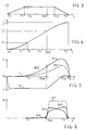
- Figures 3 and 4 show the speed-time and space-time equations of motion which govern the operation to open the interrupter of Figure 1, respectively.
- the speed increases linearly from zero to a working value of the order of 10m/s which remains constant for a time interval of the order of 10-14 ms.
- This interval is followed by a time interval T2-T3 in which the speed decreases to 0.
- the geometrical dimensions of the interrupter are such that the arcing time TC is immediately after the time T1 or coincides therewith and the minimum arcing time TAM is before the time T2.
- Figure 5 shows qualitatively the excess pressure and vacuum phenomena which develop in the compression chamber 7 and in the suction chamber 12, respectively.
- the pressure in the chamber 12 would fall abruptly to 0 and would remain at zero as long as the chamber were not in communication with an environment at a higher pressure.
- the pressure curve is as shown qualitatively by the graph PS.
- the energy which is radiated predominantly in the arcing chamber, heats the gas housed therein and increases its pressure.
- the diaphragm 11 closing the arcing chamber acts as a radiation reflector so that a large portion of the arc radiation is transmitted through the holes 14 to the gas housed in the compression chamber, which is also heated.
- the amount of radiation and its distribution over time depend on the intensity of the current and on the phase relationship between the opening of the contacts and the current wave.
- the operation of the interrupter is in fact not synchronized with the alternating current to be interrupted, which may have any value at the moment TC.
- the cumulative change in the pressure of the gas in the compression chamber is shown qualitatively by the graph PCC which extends almost up to the minimum arcing time TAM.
- T4 if T4 is slightly before TAM, the holes 14 keep the arcing chamber in communication with the compression chamber.
- the arc radiation which is also absorbed partially and locally by the non-metallic parts such as the neck 5A of the nozzle 5 and the insulating screen 16, causes surface evaporation of these parts and the formation of a gas bubble with a very high temperature and correspondingly very low density, which virtually obstructs the lines between the neck of the nozzle and the fixed contact 1.
- the energy dissipated by the electric arc is slight and the increase of pressure in the compression chamber is due essentially solely to the change in volume of the chamber.
- This flow effectively extinguishes the arc in conditions of maximum speed of movement apart of the contacts (even with an arcing time less than the minimum arcing time) so that the risk of re-striking of the arc is excluded.
- the compressed gas housed in the chamber 7 can thus flow through the ducts 18 towards the arcing chamber 10 and from there towards the suction chamber 12.
- the simultaneous opening of the neck of the nozzle 4 which is no longer obstructed by the fixed contact 1 also allows the gas housed in the arcing chamber 10 to flow towards the ambient space in the casing 2.
- the magnitudes of the two flows are determined essentially by the pressure difference existing between the compression chamber and the suction chamber.
- This pressure difference is particularly high because it is due to the excess pressure in the compression chamber intensified by the thermal effect of the arc, and to the vacuum present in the suction chamber which is still at its absolute maximum value.
- Two particularly intense flows QS and QN are thus established in a practically instantaneous manner, limited solely by the inertia of the fluid and by the speed of propagation of the pressure/vacuum wave, one flow QS decreasing with time as a result of the gradual filling of the suction chamber which is not offset by a corresponding increase of volume, and the other flow QN increasing with time as a result of the reduction in the volume of the compression chamber with an ever higher instantaneous volumetric compression ratio dV/V, even if the instantaneous change in volume dV/dt decreases.
- the pressure in the compression chamber varies qualitatively as shown in Figure 5 by the graph PC1 (in the case of the interruption of high-intensity current) or PN1 in the case of weak-intensity current, and the pressure in the suction chamber varies according to the graph PS, quickly reaching a value near or equal to the ambient pressure of the space in the casing 2 which is reached at a time T5 slightly before the time T3 at which the interrupter is fully open.
- the exhaust holes 15 are advantageously disposed along the travel of the piston 13 so that the suction chamber 12 is put into communication with the space in the casing at least starting from the time T5.
- a slight excess pressure in the suction chamber relative to the pressure in the space in the casing thus produces a gas flow from the suction chamber towards the exterior, which limits the excess pressure and enables the flow QS to be maintained, even though it is decreasing, until the interrupter is fully open.
- the suction chamber may also be kept at a vacuum relative to the casing pressure until the interrupter is fully open (time T3).
- the entire volume of the gas initially present in the compression chamber is used to produce two arc-extinguishing flows which are discharged partly into the casing space 2 and partly into the suction chamber.
- the interrupter can thus perform an effective and constant arc-extinguishing action at some moment in time between TAM and T3 when the arc current passes through its natural zero, which event is completely asynchronous with the opening of the interrupter.
- Figures 7, 8, 9, 10 show, in comparative form, the mass flows developed by interrupters of various types having compression chambers of equal volume, the same travel and the same equations of motion.
- Figure 7 shows the mass flow developed by a conventional double-flow puffer interrupter.
- Figure 8 shows the flow developed by an interrupter with suction/compression chambers.
- Figure 9 shows the flow developed by a hybrid interrupter and, finally, Figure 10 shows the flow developed by an interrupter formed according to the present invention.
- a steady suction flow QS (due to the suction chamber) is initiated from the time TC and a nozzle flow QN is initiated at the time TU.
- the cumulative flow increases linearly from the time TU starting from a higher base and with a lesser gradient than in the previous case.
- the useful extinguishing flow QOFF is achieved at a time TAM closer to TU, as in the case of the interrupter with a suction chamber.
- the volume of the gas removed from the compression chamber and corresponding to the excess flow relative to the useful extinguishing flow QOFF is also wasted.
- the two flows QN and QS which increase and decrease with time, respectively, give rise to a cumulative flow which is almost uniform over time because the vacuum in the suction chamber decreases, compensating for the increase in pressure in the compression chamber, keeping the pressure differential between the two chambers at a substantially constant level.
- a further important aspect is that the advance of the minimum arcing time TAM relative to the time T3 when the interrupter is fully open defines a useful arc-extinguishing interval or "fault clearable interval" which is longer the greater the advance of TAM.
- the useful arc-extinguishing interval is not a variable parameter but is a predetermined design condition which depends upon the working conditions.
- the useful arc-extinguishing interval has to be a little greater than 10 ms which is a half-period of a voltage and current wave.
- the volume of gas housed in the suction chamber can flow to the exterior through the holes 15 and towards the arcing chamber through the holes 14.
- gas can flow into the compression chamber (which, during the closure operation operates as a suction chamber) through the neck of the nozzle 5, which is open, and through the ducts 18.
- the closure of the interrupter is therefore carried out in conditions in which resisting forces are negligible and with minimal power and work, so that the closure operation can also be particularly quick.
- the arcing chamber is formed so as to constitute an optical cavity, preferably with metallic surfaces rendered mirror-like by lapping processes and the like and reflectors which transmit the radiation towards the compression chamber through the holes 14.
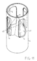
- Figure 11 is a perspective view of a portion of the operating rod 4 showing a preferred embodiment of the diaphragm 14 which closes the arcing chamber.
- the radial holes 14 for communication between the arcing chamber and the compression chamber cannot constitute a continuous annular hole because mechanical continuity with sufficient mechanical strength has to be ensured between the part of the rod which is disposed above the holes and that disposed below them.
- the various holes 14 are separated by upright elements connecting the upper and lower portions of the rod and having dimensions and a screening effect on the arc radiation equal to or even greater than the radiating section offered by the holes 14.
- the diaphragm 11, which is disposed at the bases of the holes 14, is advantageously shaped like a pyramid with a number of faces 40, 41 with concavities shaped like paraboloids of revolution equal to the number of holes 14 and facing them.
- the axis of each paraboloid of revolution is preferably oriented in the same direction as the axis of the operating rod or diverges therefrom by an angle no greater than 30°.
- the focus of each paraboloid is located in the plane of an associated hole 14 or slightly outside the outer cylindrical surface of the rod.
- the upright connecting elements between the upper and lower parts of the operating rod could be constituted by vertical connecting plates disposed radially instead of by the cylindrical wall of the rod, so as to reduce the screening effect to a minimum.
Landscapes
- Circuit Breakers (AREA)
- Burglar Alarm Systems (AREA)
- Arc-Extinguishing Devices That Are Switches (AREA)
- High-Tension Arc-Extinguishing Switches Without Spraying Means (AREA)
Claims (8)
- Ein Gasdielektrikuum-Hochspannungsunterbrecher des Lichtbogen-Puffertyps mit folgenden Merkmalen:der Stab (4) Löcher (14) zur Kommunikation zwischen einer Lichtbogenkammer (10) und der Druckkammer (7) für Positionen des beweglichen Stabes (4), die einem ersten Bruchteil des Öffnungsweges entsprechen, und zur Kommunikation zwischen der Lichtbogenkammer (10) und der Saugkammer (12) für Positionen des Stabes, die einem zweiten Bruchteil des Öffnungsweges entsprechen, der von dem ersten Bruchteil getrennt ist, aufweist.einem ersten festen Kontakt (1) und einem Kontakt (3), der relativ zu dem festen Kontakt (1) bewegbar ist und durch einen Betätigungsstab (4) geöffnet wird, in den eine Lichtbogenkammer (10) gebildet ist, wobei der Stab (4) einen vorbestimmten Öffnungsweg D aufweist,einer bewegbaren Anordnung, die an dem Stab befestigt ist, und die eine isolierende Düse (5) mit einem Düsenhals, der auf dem festen Kontakt (1) verschiebbar ist, einen Zylinder (6), der mit dem Stab (4) und der Düse (5) eine Druckkammer (7) bildet, die durch einen ersten Kolben (8) geschlossen ist, der relativ zu dem ersten Kontakt (1) befestigt ist und durch einen Trägerzylinder (9) getragen wird, und einen zweiten Kolben (13) aufweist, der an dem Stab (4) befestigt ist und in dem Trägerzylinder (9) bewegbar ist, wobei der erste befestigte Kolben (8), der Trägerzylinder (9) und der bewegbare Stab eine Saugkammer (12) bilden, die durch den zweiten Kolben (13) geschlossen ist, dadurch gekennzeichnet, daß
- Ein Unterbrecher gemäß Anspruch 1, bei dem die axialen Längen der Kommunikationslöcher (14) des Stabs (4) nicht größer sind als die axiale Abmessung des ersten Kolbens (8).
- Ein Unterbrecher gemäß Anspruch 1 oder 2, bei dem sich der zweite Bruchteil des Öffnungsweges zwischen einer Position des Stabes (4), bei der der Hals der isolierenden Düse (5) in die Lichtbogenkammer (12) vollständig offen ist und die Kommunikationslöcher (14) beginnen, sich in die Saugkammer (12) zu öffnen, und einer Öffnungsweggrenzposition des Stabes (4) befindet.
- Ein Unterbrecher gemäß einem der Ansprüche 1,2 und 3, bei dem die Lichtbogenkammer (10) zylindrisch ist und an einem Ende durch eine spitzenförmige Membrane (11) geschlossen ist, wobei der Scheitelpunkt derselben hin zu dem festen Kontakt (1) ausgerichtet ist.
- Ein Unterbrecher gemäß einem der Ansprüche 1, 2, 3 und 4, der eine Mehrzahl von Austrittslöchern (15), die in dem Trägerzylinder (9) gebildet sind und sich in die Saugkammer (12) öffnen, für Positionen des bewegbaren Stabes (4) aufweist, die einem End-Bruchteil des Öffnungsweges entsprechen.
- Ein Unterbrecher gemäß einem der vorhergehenden Ansprüche, der mindestens ein Einwegflußventil (17) in dem ersten Kolben aufweist, wobei das Ventil (17) durch einen übermäßigen Druck in der Saugkammer (12) relativ zu dem Druck in der Druckkammer (7) geöffnet wird, wodurch die Saugkammer (12) in eine Kommunikation mit der Druckkammer (7) gebracht wird.
- Ein Unterbrecher gemäß den vorhergehenden Ansprüchen, bei dem der Stab (4) einen optischen Reflektor (11) mit einer Mehrzahl von reflektierenden Oberflächen (40, 41) aufweist, wobei jede derselben zum Fokussieren von Strahlung, die durch den Lichtbogen in der Lichtbogenkammer (10) erzeugt wird, in einem oder über eines der Kommunikationslöcher (14) hinaus dient.
- Ein Unterbrecher gemäß Anspruch 7, bei dem die reflektierenden Oberflächen (40, 41) Segmente von Rotationsparaboloiden sind, die Achsen aufweisen, die von der Achse des Stabes (4) um weniger als 30° abweichen.
Priority Applications (6)
| Application Number | Priority Date | Filing Date | Title |
|---|---|---|---|
| EP95830180A EP0741399B1 (de) | 1995-05-04 | 1995-05-04 | Hochspannungsschalter mit dielektrischem Gas mit Selbst-Beblasung |
| AT95830180T ATE176082T1 (de) | 1995-05-04 | 1995-05-04 | Hochspannungsschalter mit dielektrischem gas mit selbst-beblasung |
| DE69507453T DE69507453T2 (de) | 1995-05-04 | 1995-05-04 | Hochspannungsschalter mit dielektrischem Gas mit Selbst-Beblasung |
| HU9601142A HUP9601142A3 (en) | 1995-05-04 | 1996-04-30 | A gas-dielectric high-tension interrupter of the arc-puffer type |
| US08/642,331 US5723840A (en) | 1995-05-04 | 1996-05-03 | Gas-dielectric high-tension interrupter of the arc-puffer type |
| BR9602157A BR9602157A (pt) | 1995-05-04 | 1996-05-06 | Interruptor de alta-tens o gás-dielétrico do tipo arco emissor |
Applications Claiming Priority (1)
| Application Number | Priority Date | Filing Date | Title |
|---|---|---|---|
| EP95830180A EP0741399B1 (de) | 1995-05-04 | 1995-05-04 | Hochspannungsschalter mit dielektrischem Gas mit Selbst-Beblasung |
Publications (2)
| Publication Number | Publication Date |
|---|---|
| EP0741399A1 EP0741399A1 (de) | 1996-11-06 |
| EP0741399B1 true EP0741399B1 (de) | 1999-01-20 |
Family
ID=8221915
Family Applications (1)
| Application Number | Title | Priority Date | Filing Date |
|---|---|---|---|
| EP95830180A Expired - Lifetime EP0741399B1 (de) | 1995-05-04 | 1995-05-04 | Hochspannungsschalter mit dielektrischem Gas mit Selbst-Beblasung |
Country Status (6)
| Country | Link |
|---|---|
| US (1) | US5723840A (de) |
| EP (1) | EP0741399B1 (de) |
| AT (1) | ATE176082T1 (de) |
| BR (1) | BR9602157A (de) |
| DE (1) | DE69507453T2 (de) |
| HU (1) | HUP9601142A3 (de) |
Families Citing this family (32)
| Publication number | Priority date | Publication date | Assignee | Title |
|---|---|---|---|---|
| DE29706202U1 (de) * | 1997-03-27 | 1997-06-05 | Siemens Ag | Druckgasleistungsschalter |
| NL1007753C2 (nl) * | 1997-12-09 | 1999-06-23 | Elin Holec High Voltage Bv | Werkwijze voor het middels een gasstroom doven van een lichtboog bij een vermogens-schakelaar alsmede vermogens-schakelaar. |
| DE19816505A1 (de) * | 1998-04-14 | 1999-10-21 | Asea Brown Boveri | Leistungsschalter |
| US6045516A (en) * | 1998-12-18 | 2000-04-04 | Phelan; James | Cleanable medical/surgical suction devices |
| USD428137S (en) * | 1999-01-06 | 2000-07-11 | James Phelan | Handle for medical surgical suction device |
| USD434140S (en) * | 1999-01-06 | 2000-11-21 | James Phelan | Medical surgical suction device |
| FR2807870B1 (fr) * | 2000-04-18 | 2002-05-24 | Alstom | Interrupteur a soufflage d'arc, possedant une chambre de coupure a compression de gaz reduite et un mouvement alternatif du piston |
| JP4218216B2 (ja) * | 2001-02-22 | 2009-02-04 | 株式会社日立製作所 | ガス遮断器 |
| FR2837321B1 (fr) * | 2002-03-18 | 2004-08-06 | Alstom | Disjoncteur haute tension comprenant un clapet de decompression |
| EP1630840B1 (de) | 2004-08-23 | 2006-12-20 | ABB Technology AG | Hochleistungsschalter mit Bewegungsumkehr |
| US7215412B2 (en) * | 2004-09-01 | 2007-05-08 | Golf Solutions 1, L.L.C. | Flagpole reflectors for laser range finders |
| US20070171394A1 (en) * | 2006-01-25 | 2007-07-26 | Daniel Steiner | Flagstick with integrated reflectors for use with a laser range finder |
| JP5021230B2 (ja) * | 2006-05-10 | 2012-09-05 | 三菱電機株式会社 | パッファ形ガス遮断器 |
| JP2008210710A (ja) * | 2007-02-27 | 2008-09-11 | Mitsubishi Electric Corp | 電力用ガス遮断器 |
| FR2937179A1 (fr) * | 2008-10-09 | 2010-04-16 | Areva T & D Sa | Chambre de coupure pour disjoncteur haute tension a soufflage d'arc ameliore |
| JP5242461B2 (ja) * | 2009-03-06 | 2013-07-24 | 株式会社東芝 | ガス遮断器 |
| EP2415060B1 (de) | 2009-03-30 | 2017-07-26 | ABB Research Ltd. | Unterbrecherschalter |
| EP2343721A1 (de) * | 2010-01-06 | 2011-07-13 | ABB Research Ltd. | Gasisolierter Hochspannungsschalter |
| US9012800B2 (en) * | 2010-02-04 | 2015-04-21 | Mitsubishi Electric Corporation | Gas circuit breaker |
| US9018558B2 (en) | 2010-05-31 | 2015-04-28 | Ormazabal Y Cia, S.L. | Gas circuit breaker |
| FR2962847B1 (fr) * | 2010-07-16 | 2012-08-17 | Areva T & D Sas | Appareillage de chambre de coupure pour deux electrodes de contact confinees |
| FR2988215B1 (fr) * | 2012-03-16 | 2014-02-28 | Schneider Electric Ind Sas | Melange d'hydrofluoroolefine et d'hydrofluorocarbure pour ameliorer la tenue a l'arc interne dans les appareils electriques moyenne et haute tension |
| DE112013001981T5 (de) * | 2012-04-11 | 2015-03-12 | Abb Technology Ag | Leistungsschalter |
| FR3008541B1 (fr) * | 2013-07-15 | 2015-08-21 | Alstom Technology Ltd | Disjoncteur a soufflage par effet piston optimise |
| ES2613430T3 (es) * | 2013-10-22 | 2017-05-24 | Gorlan Team, S.L.U. | Interruptor eléctrico reconfigurable |
| EP3196911B1 (de) * | 2013-10-22 | 2019-01-09 | Gorlan Team, S.L.U. | Schraubenförmiger Schalter |
| USD754015S1 (en) | 2014-06-04 | 2016-04-19 | Prestige Flag Mfg. Co., Inc. | Flagstick reflector |
| USD741971S1 (en) | 2014-06-04 | 2015-10-27 | Prestige Flag Mfg. Co., Inc. | Flagstick reflector module |
| USD790396S1 (en) | 2016-03-01 | 2017-06-27 | Prestige Flag Mfg. Co., Inc. | Flagstick reflector insert |
| DE102018211621A1 (de) | 2018-07-12 | 2020-01-16 | Siemens Aktiengesellschaft | Gasisolierter Schalter |
| JP2021051903A (ja) * | 2019-09-25 | 2021-04-01 | 株式会社日立製作所 | ガス遮断器 |
| CN110690074B (zh) * | 2019-09-29 | 2021-05-04 | 山东理工大学 | 一种带有除水功能的sf6高压断路器灭弧室 |
Family Cites Families (16)
| Publication number | Priority date | Publication date | Assignee | Title |
|---|---|---|---|---|
| US3946183A (en) * | 1974-04-05 | 1976-03-23 | Westinghouse Electric Corporation | Puffer piston gas blast circuit interrupter with insulating nozzle member |
| US4000387A (en) * | 1974-05-13 | 1976-12-28 | Westinghouse Electric Corporation | Puffer-type gas circuit-interrupter |
| US4075447A (en) * | 1975-03-21 | 1978-02-21 | Westinghouse Electric Corporation | Double-puffer-type compressed-gas circuit-interrupter constructions |
| US4095068A (en) * | 1976-05-12 | 1978-06-13 | Westinghouse Electric Corp. | Stationary-contact-and voltage-shield assembly for a gas-puffer-type circuit-interrupter |
| US4160888A (en) * | 1976-06-10 | 1979-07-10 | Hitachi, Ltd. | Puffer-type gas-blast circuit breaker |
| US4163131A (en) * | 1977-08-11 | 1979-07-31 | Westinghouse Electric Corp. | Dual-compression gas-blast puffer-type interrupting device |
| JPS5465503A (en) * | 1977-11-04 | 1979-05-26 | Hitachi Ltd | Information recorder-reproducer |
| US4205208A (en) * | 1978-03-16 | 1980-05-27 | Westinghouse Electric Corp. | Double-flow compressed-gas operating mechanism for a high-voltage circuit-breaker |
| DE7906561U1 (de) * | 1979-03-09 | 1983-05-05 | Licentia Patent-Verwaltungs-Gmbh, 6000 Frankfurt | Autopneumatischer Druckgasschalter |
| EP0019806B1 (de) * | 1979-05-25 | 1983-11-30 | Mitsubishi Denki Kabushiki Kaisha | Leistungsschalter mit Anordnung zur Lichtbogenlöschung |
| DE3134200A1 (de) * | 1981-08-27 | 1983-03-10 | Siemens AG, 1000 Berlin und 8000 München | Elektrischer schalter |
| US4560142A (en) * | 1982-11-12 | 1985-12-24 | Charles Winn (Valves) Limited | Butterfly and ball valves |
| ATE32286T1 (de) * | 1983-11-15 | 1988-02-15 | Sprecher Energie Ag | Druckgasschalter. |
| IT8420810V0 (it) * | 1984-02-10 | 1984-02-10 | Sace Spa | Sistema di contatti d'arco per interruttori elettrici, particolarmente a fluido d'estinzione dell'arco. |
| US4841108A (en) * | 1987-11-06 | 1989-06-20 | Cooper Industries, Inc. | Recloser plenum puffer interrupter |
| US5059753A (en) * | 1987-11-06 | 1991-10-22 | Cooper Industries, Inc. | SF6 puffer recloser |
-
1995
- 1995-05-04 EP EP95830180A patent/EP0741399B1/de not_active Expired - Lifetime
- 1995-05-04 AT AT95830180T patent/ATE176082T1/de not_active IP Right Cessation
- 1995-05-04 DE DE69507453T patent/DE69507453T2/de not_active Expired - Fee Related
-
1996
- 1996-04-30 HU HU9601142A patent/HUP9601142A3/hu unknown
- 1996-05-03 US US08/642,331 patent/US5723840A/en not_active Expired - Fee Related
- 1996-05-06 BR BR9602157A patent/BR9602157A/pt not_active IP Right Cessation
Also Published As
| Publication number | Publication date |
|---|---|
| BR9602157A (pt) | 1997-12-30 |
| HU9601142D0 (en) | 1996-06-28 |
| EP0741399A1 (de) | 1996-11-06 |
| HUP9601142A2 (en) | 1997-05-28 |
| ATE176082T1 (de) | 1999-02-15 |
| HUP9601142A3 (en) | 1999-04-28 |
| US5723840A (en) | 1998-03-03 |
| DE69507453T2 (de) | 1999-09-02 |
| DE69507453D1 (de) | 1999-03-04 |
Similar Documents
| Publication | Publication Date | Title |
|---|---|---|
| EP0741399B1 (de) | Hochspannungsschalter mit dielektrischem Gas mit Selbst-Beblasung | |
| US20140190938A1 (en) | Puffer type gas circuit breaker | |
| JPS6182631A (ja) | 圧縮ガス遮断器 | |
| JPH1031945A (ja) | 電力遮断器 | |
| US6744001B2 (en) | High-voltage circuit-breaker including a valve for decompressing a thermal blast chamber | |
| JPH10149750A (ja) | 電力用遮断器 | |
| JP2655733B2 (ja) | 中高電圧回路遮断器 | |
| CN101599391B (zh) | 单断口单气缸自能式高压六氟化硫断路器灭弧室 | |
| JP2657108B2 (ja) | 絶縁ガス吹付け式中電圧回路遮断器 | |
| CN112002605B (zh) | 一种开关设备及其灭弧室 | |
| US3787648A (en) | Tank-type gas-break circuit breaker | |
| EP2648202A1 (de) | Schutzschalter | |
| RU2811082C1 (ru) | Коммутационное устройство и дугогасящая камера для него | |
| EP3985703B1 (de) | Leistungsschalter mit verbessertem gasströmungsmanagement | |
| CN112289628B (zh) | 一种双压力膨胀室灭弧室 | |
| CN204424148U (zh) | 环保型磁力断路器灭弧室 | |
| JP2002075146A (ja) | パッファ形ガス遮断器 | |
| JPH0439627Y2 (de) | ||
| KR20220046124A (ko) | 복합 소호형 가스 차단기 | |
| JP2003317584A (ja) | 熱パッファ形ガス遮断器 | |
| JP2020119766A (ja) | ガス遮断器 | |
| JP2004055162A (ja) | ガス遮断器 | |
| JP2635559B2 (ja) | パツフア形ガス遮断器 | |
| JP2019220301A (ja) | ガス遮断器 | |
| JP2016062650A (ja) | ガス遮断器 |
Legal Events
| Date | Code | Title | Description |
|---|---|---|---|
| PUAI | Public reference made under article 153(3) epc to a published international application that has entered the european phase |
Free format text: ORIGINAL CODE: 0009012 |
|
| 17P | Request for examination filed |
Effective date: 19960318 |
|
| AK | Designated contracting states |
Kind code of ref document: A1 Designated state(s): AT CH DE FR GB IT LI NL SE |
|
| AX | Request for extension of the european patent |
Free format text: LT;SI |
|
| RAX | Requested extension states of the european patent have changed |
Free format text: LT;SI |
|
| GRAG | Despatch of communication of intention to grant |
Free format text: ORIGINAL CODE: EPIDOS AGRA |
|
| 17Q | First examination report despatched |
Effective date: 19980429 |
|
| GRAG | Despatch of communication of intention to grant |
Free format text: ORIGINAL CODE: EPIDOS AGRA |
|
| GRAH | Despatch of communication of intention to grant a patent |
Free format text: ORIGINAL CODE: EPIDOS IGRA |
|
| GRAH | Despatch of communication of intention to grant a patent |
Free format text: ORIGINAL CODE: EPIDOS IGRA |
|
| GRAA | (expected) grant |
Free format text: ORIGINAL CODE: 0009210 |
|
| RBV | Designated contracting states (corrected) |
Designated state(s): AT CH DE FR GB IT LI NL SE |
|
| AK | Designated contracting states |
Kind code of ref document: B1 Designated state(s): AT CH DE FR GB IT LI NL SE |
|
| REF | Corresponds to: |
Ref document number: 176082 Country of ref document: AT Date of ref document: 19990215 Kind code of ref document: T |
|
| REG | Reference to a national code |
Ref country code: CH Ref legal event code: EP |
|
| REF | Corresponds to: |
Ref document number: 69507453 Country of ref document: DE Date of ref document: 19990304 |
|
| ITPR | It: changes in ownership of a european patent |
Owner name: CESSIONE EPO REG. 20;ANSALDO TRASMISSIONE E DISTRI |
|
| ITF | It: translation for a ep patent filed |
Owner name: JACOBACCI & PERANI S.P.A. |
|
| PG25 | Lapsed in a contracting state [announced via postgrant information from national office to epo] |
Ref country code: DE Free format text: LAPSE BECAUSE OF FAILURE TO SUBMIT A TRANSLATION OF THE DESCRIPTION OR TO PAY THE FEE WITHIN THE PRESCRIBED TIME-LIMIT Effective date: 19990421 |
|
| ET | Fr: translation filed | ||
| RAP2 | Party data changed (patent owner data changed or rights of a patent transferred) |
Owner name: ANSALDO TRASMISSIONE E DISTRIBUZIONE S.R.L. |
|
| REG | Reference to a national code |
Ref country code: CH Ref legal event code: PUE Owner name: ANSALDO INDUSTRIA S.P.A. TRANSFER- ANSALDO TRASMIS Ref country code: CH Ref legal event code: NV Representative=s name: JACOBACCI & PERANI S.A. |
|
| NLT2 | Nl: modifications (of names), taken from the european patent patent bulletin |
Owner name: ANSALDO TRASMISSIONE E DISTRIBUZIONE S.R.L. |
|
| PLBE | No opposition filed within time limit |
Free format text: ORIGINAL CODE: 0009261 |
|
| STAA | Information on the status of an ep patent application or granted ep patent |
Free format text: STATUS: NO OPPOSITION FILED WITHIN TIME LIMIT |
|
| 26N | No opposition filed | ||
| REG | Reference to a national code |
Ref country code: GB Ref legal event code: 732E |
|
| NLS | Nl: assignments of ep-patents |
Owner name: ANSALDO TRASMISSIONE E DISTRIBUZIONE S.R.L. |
|
| REG | Reference to a national code |
Ref country code: GB Ref legal event code: IF02 |
|
| PGFP | Annual fee paid to national office [announced via postgrant information from national office to epo] |
Ref country code: SE Payment date: 20020328 Year of fee payment: 8 |
|
| PGFP | Annual fee paid to national office [announced via postgrant information from national office to epo] |
Ref country code: AT Payment date: 20020409 Year of fee payment: 8 |
|
| PGFP | Annual fee paid to national office [announced via postgrant information from national office to epo] |
Ref country code: NL Payment date: 20020415 Year of fee payment: 8 |
|
| PGFP | Annual fee paid to national office [announced via postgrant information from national office to epo] |
Ref country code: CH Payment date: 20020416 Year of fee payment: 8 |
|
| PGFP | Annual fee paid to national office [announced via postgrant information from national office to epo] |
Ref country code: GB Payment date: 20020417 Year of fee payment: 8 |
|
| PGFP | Annual fee paid to national office [announced via postgrant information from national office to epo] |
Ref country code: DE Payment date: 20020423 Year of fee payment: 8 |
|
| PGFP | Annual fee paid to national office [announced via postgrant information from national office to epo] |
Ref country code: FR Payment date: 20020530 Year of fee payment: 8 |
|
| PG25 | Lapsed in a contracting state [announced via postgrant information from national office to epo] |
Ref country code: GB Free format text: LAPSE BECAUSE OF NON-PAYMENT OF DUE FEES Effective date: 20030504 Ref country code: AT Free format text: LAPSE BECAUSE OF NON-PAYMENT OF DUE FEES Effective date: 20030504 |
|
| PG25 | Lapsed in a contracting state [announced via postgrant information from national office to epo] |
Ref country code: SE Free format text: LAPSE BECAUSE OF NON-PAYMENT OF DUE FEES Effective date: 20030505 |
|
| PG25 | Lapsed in a contracting state [announced via postgrant information from national office to epo] |
Ref country code: LI Free format text: LAPSE BECAUSE OF NON-PAYMENT OF DUE FEES Effective date: 20030531 Ref country code: CH Free format text: LAPSE BECAUSE OF NON-PAYMENT OF DUE FEES Effective date: 20030531 |
|
| PG25 | Lapsed in a contracting state [announced via postgrant information from national office to epo] |
Ref country code: NL Free format text: LAPSE BECAUSE OF NON-PAYMENT OF DUE FEES Effective date: 20031201 |
|
| GBPC | Gb: european patent ceased through non-payment of renewal fee |
Effective date: 20030504 |
|
| EUG | Se: european patent has lapsed | ||
| REG | Reference to a national code |
Ref country code: CH Ref legal event code: PL |
|
| PG25 | Lapsed in a contracting state [announced via postgrant information from national office to epo] |
Ref country code: FR Free format text: LAPSE BECAUSE OF NON-PAYMENT OF DUE FEES Effective date: 20040130 |
|
| NLV4 | Nl: lapsed or anulled due to non-payment of the annual fee |
Effective date: 20031201 |
|
| REG | Reference to a national code |
Ref country code: FR Ref legal event code: ST |
|
| PG25 | Lapsed in a contracting state [announced via postgrant information from national office to epo] |
Ref country code: IT Free format text: LAPSE BECAUSE OF NON-PAYMENT OF DUE FEES;WARNING: LAPSES OF ITALIAN PATENTS WITH EFFECTIVE DATE BEFORE 2007 MAY HAVE OCCURRED AT ANY TIME BEFORE 2007. THE CORRECT EFFECTIVE DATE MAY BE DIFFERENT FROM THE ONE RECORDED. Effective date: 20050504 |