EP0740300B1 - Kopfbetätigungsorgan für Plattenantriebssystem - Google Patents
Kopfbetätigungsorgan für Plattenantriebssystem Download PDFInfo
- Publication number
- EP0740300B1 EP0740300B1 EP96106431A EP96106431A EP0740300B1 EP 0740300 B1 EP0740300 B1 EP 0740300B1 EP 96106431 A EP96106431 A EP 96106431A EP 96106431 A EP96106431 A EP 96106431A EP 0740300 B1 EP0740300 B1 EP 0740300B1
- Authority
- EP
- European Patent Office
- Prior art keywords
- actuator
- axis
- carriage
- flat
- coil
- Prior art date
- Legal status (The legal status is an assumption and is not a legal conclusion. Google has not performed a legal analysis and makes no representation as to the accuracy of the status listed.)
- Expired - Lifetime
Links
Images




Classifications
-
- G—PHYSICS
- G11—INFORMATION STORAGE
- G11B—INFORMATION STORAGE BASED ON RELATIVE MOVEMENT BETWEEN RECORD CARRIER AND TRANSDUCER
- G11B5/00—Recording by magnetisation or demagnetisation of a record carrier; Reproducing by magnetic means; Record carriers therefor
- G11B5/48—Disposition or mounting of heads or head supports relative to record carriers ; arrangements of heads, e.g. for scanning the record carrier to increase the relative speed
-
- G—PHYSICS
- G11—INFORMATION STORAGE
- G11B—INFORMATION STORAGE BASED ON RELATIVE MOVEMENT BETWEEN RECORD CARRIER AND TRANSDUCER
- G11B21/00—Head arrangements not specific to the method of recording or reproducing
- G11B21/02—Driving or moving of heads
- G11B21/08—Track changing or selecting during transducing operation
- G11B21/081—Access to indexed tracks or parts of continuous track
- G11B21/083—Access to indexed tracks or parts of continuous track on discs
- G11B21/085—Access to indexed tracks or parts of continuous track on discs with track following of accessed part
Definitions
- the present invention relates to a disk drive, such as a magnetic disk drive, a magnetic disk cartridge drive or an optical disk drive, which is widely used as an external storage device for a computer and, more particularly, to a disk drive which has an improved head actuator for selectively positioning a read and/or write head with respect to the rotating disk storage medium.
- a magnetic disk drive has remarkably improved, in recent years, the storage density of a magnetic disk as a storage medium, and has increased its storage capacity by a factor of at least 10 times during the period of about 10 years. Improvement in the storage density can be realized in both a circumferential direction and a track direction of a magnetic disk.
- the former is represented by the number of bits per inch (“BPI”) and the latter is represented by the number of tracks per inch (“TPI").
- BPI bits per inch
- TPI tracks per inch
- the number of TPI has now reached 4,000 TPI (6.0 ⁇ m in track pitch) and is expected to be further increased to 10,000 TPI (2.5 ⁇ m in track pitch).
- the track pitch becomes 2.5 ⁇ m and the tolerable positioning error is about 10% of the pitch, that is, 0.25 ⁇ m or less.
- a disk drive must be downsized for use in a portable personal computer. Accordingly, disturbances (e.g., shock or vibration) to the disk relatively increase. Further, it is difficult to satisfy the two inconsistent factors of increasing disturbances and decreasing tolerable positioning errors.
- disturbances e.g., shock or vibration
- a basic solution for this problem is to provide a head positioning servo system having a wide servo band.
- an inherent vibration characteristic of a head actuator prevents the servo system from obtaining with a sufficiently wide servo band.
- the resonance frequency of a typical actuator is generally several kHz and it has been almost impossible to obtain the servo band of 1 kHz or higher. If the servo band were unreasonably widened under this condition to include the actuator resonance frequency, the control system would become unstable and the positioning accuracy would decrease.
- the servo band has been widened using a double-actuator in a certain optical disk drive where the track pitch is about 1.5 ⁇ m. Thereby, the servo band can be improved up to about 2 kHz. It is also possible to introduce, into a magnetic disk drive, the double-actuator which has been used for an optical disk drive, and many various attempts to do so have been conducted. However, these attempts cannot yet be put into commercial use. Because a magnetic disk drive has about 10 to 20 heads, it is impractical to use such a large number of double-actuators from the viewpoints of price and weight. Especially since magnetic disk drives recently are in a trend of significant cost reduction, it is considerably difficult to employ technology which results in an increase of cost. Meanwhile, although only one head is used in a typical optical disk drive, realization of low cost is also precluded by the double-actuator and a complicated control system required for driving such a double-actuator.
- the resonance frequency of one type can be raised, but the resonance frequency of another type may be lowered.
- the former is a resonance frequency in an "elastic body mode” and the latter is a resonance frequency in a "rigid body mode".
- the resonance frequency of the elastic body mode is caused by elasticity of the actuator itself, and the resonance frequency of the rigid body mode is caused by a spring characteristic between a movable part and a stationary part through a bearing while maintaining the actuator as an almost rigid body.
- the resonance frequency of the rigid body mode is inversely proportional to a square root of the mass of the body when the spring characteristic is constant, and is lower in frequency than the resonance frequency of the elastic body mode.
- the resonance frequency of the elastic body mode rises, however, this creates a problem of the resonance frequency of the rigid body mode being lowered due to an increase in the weight (mass) of the actuator, in addition to creating a further problem that the access performance is lowered due to a heavier actuator.
- the resonance frequency in the rigid body mode is increased.
- the resonance frequency of the elastic body mode is lowered due to a decrease of the rigidity of the actuator. Therefore, it is essentially impossible to realize respective, higher resonance frequencies of both the rigid body mode and the elastic body mode.
- Fig. 1 is a top view of a conventional head actuator using a single coil unit, which generally has been used in the prior art.
- Fig. 2 shows a vibration-frequency characteristic of such a prior art actuator.
- a head actuator 50 has a head 51 for reading/writing data from/to a rotating magnetic disk 52, a suspension arm 57 supporting the head 51, a carriage arm 53 supporting the suspension arm 57, a bearing 54, a stationary shaft 55 for rotatably supporting the carriage arm 53 through the bearing 54, and a coil 56 attached to the arm 53.
- the coil 56 generates driving forces F and F' in cooperation with a magnet not shown in Fig. 1.
- the head 51 swings along a head positioning direction (i.e., a seek direction) represented by an arrow E.
- a peak 61 corresponding to the resonance frequency of the actuator 50 in the rigid body mode, occurs at a frequency of several kHz.
- the vibration in the rigid body mode of the actuator 50 produces a displacement of the actuator 50 indicated by a chain line 59 of Fig. 1, the direction of 59 being parallel to the seek direction E, because the driving forces F and F' are generated in the direction parallel to the seek direction E.
- the driving forces F and F' generated during a transition from a stationary position to a condition of movement, produces the vibration in the direction parallel to the seek direction E.
- the servo band is designed to be below the frequency where the peak 61 appears, because the head positioning error may become larger at such frequency.
- a peak 62 corresponding to the resonance frequency of the elastic body mode, occurs at the frequency higher than the resonance frequency of the rigid body mode.
- the head positioning direction does not perpendicularly cross the circumferential direction of the disk medium due to an existence of a yaw angle, but such a yaw angle has only a small influence because the yaw angle is within 20°.
- a disk drive which mounts the head actuator while avoiding any interference between the disk medium and the head actuator while achieving the above object.
- a balanced drive using a pair of coils are described in the Japanese Patent Laid-Open Nos. SHO 59-116965, HEI 5-54565 and HEI 6-124553.
- these prior art drives are also accompanied by a practical problem in that it is very difficult to mount the head actuator efficiently in the limited space of a disk drive while avoiding interference with a disk medium.
- a rotary moving coil actuator for selectively positioning a read/write head with respect to a rotating disk medium in a disk drive, said actuator comprising: a carriage pivotable about an axis and having a carriage arm for supporting the read/write head; a pair of yoke plates fixed on the disk drive in spaced relationship; a pair of magnets fixed between said pair of yoke plates and having respective flat faces which are perpendicular to the axis and which face each other with a gap therebetween; and at least one flat coil attached to said carriage and disposed at least in part in the gap between, and facing, the flat faces of said magnets, the at least one flat coil being movable along a stroke of movement relative to the flat faces of said magnets; characterised in that: the at least one flat coil is so arranged relative to said magnets, as to generate a driving force in a direction approximately parallel to a first line which is perpendicular to the axis and passes through the axis and the read/write
- Fig. 3 which illustrates the principle of the present invention
- the moving coil when the head 71 is positioned with respect to the surface of the rotating disk 72, as the storage medium, the moving coil generates a driving force F" in the direction perpendicular to the seek direction E". Accordingly, even though mechanical vibrations might appear in the direction C", such mechanical vibrations effectively produce no head positioning error because a disk drive has a large acceptable margin against such mechanical vibrations.
- the coil is formed as a flat coil arranged in a plane parallel to the disk medium, the actuator can be mounted within the space of a comparatively thinner disk drive, thereby to improve the mounting efficiency.
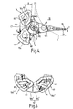
- Fig. 4 is a top plane view of a preferred embodiment (first embodiment) of the improved head actuator of the present invention
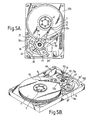
- Fig. 5A is a top plane view of a 3.5-inch disk drive utilizing the head actuator of Fig. 4
- Fig. 5B is a perspective view of the disk drive of Fig. 5A.
- a plurality of circular disks 1 are stacked in the vertical direction while keeping predetermined spaces therebetween, as the magnetic storage media rotate in common on the spindle shaft 2.
- a movable part of the actuator 10 comprises a carriage 12 having a plurality of carriage arms 12a, integral with and extending radially from a coil mounting base 12b rotatably mounted on a shaft 11, a plurality of suspension arms 14 extending, respectively, from the plurality of carriage arms 12a and carrying on the free ends thereof a respective plurality of magnetic read/write heads 15 and, further, a pair of moving flat coils 16 and 17.
- a bearing 110 is mounted on the shaft 11 and rotatably supports the movable part of the actuator 10 on the shaft 11.
- a stationary part of the actuator 10 comprises the shaft 11 and a magnetic circuit respectively fixed on an enclosure 100 (Fig. 5A) of the disk drive.
- the magnetic circuit comprises a pair of flat permanent magnets 18 and 18' which are of substantially identical configuration and are disposed in spaced, parallel relationship and which receive the pair of moving coils 16 and 17 therebetween.
- the upper magnet 18 i.e., "upper", as in the orientation of Figs. 5A and 5B
- the magnetic circuit further comprises a pair of main yoke plates 20 (Fig. 5A) and 20' (Fig.
- the carriage arms 12a extend to and can overlap and move along, and relatively to, the corresponding surfaces of the respective disks 1.
- the heads 15 are respectively mounted on the ends of the corresponding suspension arms 14 and the suspension arms 14 are respectively mounted on the corresponding ends of the carriage arms 12a.
- the coils 16 and 17 are mounted on the coil mounting base 12b at the opposite side of the shaft 11 from the heads 15 and between the magnets 18 and 18', and are movable within the gap between, and relatively to the surfaces of, the magnets 18 and 18'. Meanwhile, the coils 16 and 17 are symmetrically disposed with respect to, and on opposite sides of, a plane which substantially includes both the axis O and a line C1 which passes through the shaft 11 and the heads 15
- the heads 15 are selectively positioned in the seek direction E1 by selective rotation of the carriage 12.
- the heads 15 stay in contact with the surface of the disks 1 while the rotation of the disks 1 has stopped, and the heads 15 are positioned close to but spaced from the surfaces of the disks 1 while the disks 1 are rotating.
- the coils 16 and 17 are flat, coreless-type coils and respectively have front portions 81 and 82 and rear portions 83 and 84.
- the coil portions 81-84 in cooperation with the magnets 18 and 18' respectively generate driving forces A, A', B and B'.
- the front portions 81 and 82 respectively generate the driving forces A and A' in opposite directions, precisely parallel to the line C1, and extend in a direction parallel to a 11 line D1 which perpendicularly crosses the line C1 and passes through the axis O. Since the coils 16 and 17 are symmetrically disposed with respect to the plane including the axis O and the line C1, the coils 16 and 17 generate respective driving forces which are substantially oppositely and symmetrically oriented, with respect to the plane.
- the front portions 81 and 82 are disposed with a predetermined offset and at an opposite side of the line D1 (and thus of the axis of rotation O) from the heads 15, and the rear portions 83 and 84 are not exactly parallel to the front portions 81 and 82 but are inclined so as to be approximately parallel to a radial direction, relatively to the shaft 11.
- the coils 16 and 17 generate a certain loss from the viewpoint of rotational torque, because the driving forces A, A', B and B' deviate slightly from a rotating direction relatively to the axis 0.
- an arrangement of the coils 16 and 17 is closely related to an arrangement of the magnetic poles of the magnetic circuit for the required stroke of the head and the required rotating angle of the head actuator; therefore, the coils 16 and 17 and the magnetic circuit must be designed so as to cooperate properly.
- Reinforcing blocks 16a and 17a are disposed within the respective coils 16 and 17 and serve both for defining and maintaining (i.e., reinforcing) the shape of the coils 16 and 17, which may be wound thereabout, and also for counterbalancing the actuator with respect to the arm extensions, etc., disposed on the opposite side of the rotating drive shaft 11.
- Fig. 6 shows an arrangement of the coils 16 and 17 of Figs. 4, 5A and 5B, from an initial (solid line) position and as moved to a displaced, dotted line position, relatively to the lower magnet 18'.
- the lower magnet 18' comprises two magnets 18a' and 18b' respectively defining N and S (two) poles each, for a total of four poles.
- the coil portions 81-84 are movable relatively to the corresponding poles (and within the gap between the lower magnet 18' and the upper magnet 18).
- the arrangement of the coil portions 81 (81') and 82 (82') of the embodiment shown in Figs. 4-6 is perfect from the viewpoint of the direction of the driving forces A and A', because the driving forces A and A' are exactly perpendicular to the seek direction E1 and are practically, exactly balanced about the shaft 11. The bearing reaction thus is reduced, due to the balanced driving forces. Moreover, since the front portions 81 and 82 are disposed with an offset from the axis O of shaft 11 (and thus from the line D1 or from a plane passing through the line D1 and in which the axis O lies) to prevent any interference with the disks 1, the driving forces A and A' slightly deviate from the rotating direction.
- the arrangements of the rear portions 83 and 84 are a compromise between the direction perpendicular to the seek direction and the loss of the driving forces B and B'.
- angles of the rear portions 83 and 84 relative to the radial direction are about 30°. Accordingly, a rotating efficiency of the driving forces B and B' is 86%, that is, the loss of the driving forces B and B' is only 14%. In total, the rotating efficiency is about 88%.
- a force component in the seek direction E1 is about 50% of the driving forces B and B' while a force component of the driving force A and A' is zero in the seek direction E1.
- the force component in the seek direction E1 is about 25%.
- This unbalanced force component in the seek direction has been reduced to about 1/4, considering that almost all the driving forces F and F' of the prior art, as shown in Fig. 1, produce an unbalanced force component in the seek direction E.
- the bearing reaction in the seek direction E1 has been reduced to about 1/4, and this is equivalent to the peak gain of the rigid body mode being reduced by as much as 12 dB.
- the peak gain in the rigid body mode is generally about 10-20 dB due to the bearing reaction when vibration of the rigid body mode is not incorporated with vibration of the other modes. Accordingly, when the head actuator of this embodiment shown in Fig. 4-6 is used, the peak gain becomes about 0-8 dB, a level which may be ignored.
- the moving part of the actuator is symmetrically arranged about the line C1 which passes through the shaft 11 and the heads 15.
- the rear portions 83 and 84 also work as balancers for the heads 15 and the carriage arms 12a, thereby to realize almost perfect balance for rotation.
- An actuator using a single flat coil (only one of the coils 16 or 17 in Fig. 4) can also obtain a good vibration characteristic. Since an object of the present invention is to provide both a good vibration characteristic and a good mountable coil structure, this single coil actuator is encompassed within the present invention. In practical use, it is preferable to mount a balancer at the opposite side of the shaft 11 from the single coil to obtain the balance of rotation.
- the efficiency of the dual coil actuator shown in Fig. 4 is described hereunder.
- the moment of inertia of the coils 16 and 17 is about 1/2 (50%) that of the total moment of the movable part, and the moment of inertia of the heads 15 and the carriage arms 12a is about 1/2 (50%) that of the total.
- the moment of inertia of the single coil actuator is about 3/4 (75%) that of the dual coil actuator, and the total driving force of the single coil actuator is 1/2 that of the dual actuator when the same current is applied to each coil.
- the amount of electric power which the single coil actuator requires, to obtain the same acceleration is about 3/2 (150%) relative to that of the dual coil actuator.
- Fig. 7 shows a three dimensional model for analysis of the movable part of the head actuator of Fig. 4.
- the head actuator is modeled as a set of a plurality of small finite elements 900.
- the bearing is modeled as a linear spring in the simulation.
- the suspension arms and the heads are given only a mass as elements 901. Therefore, the actuator is considered as a whole, but the vibration characteristics of the individual suspension arms are not considered.
- Designs for the rigid body mode are based on the arrangements of the coils as described above.
- designs for the elastic mode are based on the arrangements of the carriage arms which are formed wider and particularly wider near the shaft.
- the wider carriage arms have increased rigidity; however, an increase of mass near the shaft does not causes a serious increase in the moment of inertia.
- holes 902 are formed in the carriage arms while, nevertheless, maintaining sufficient rigidity of the carriage arms.
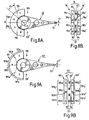
- Fig. 8A is a top plane view of a four-pole magnet arrangement on the carriage 10 of Figs. 4, 5A and 5B.
- Fig. 8B is a sectional view taken in a curved plane substantially along an arcuate (circumferential) line 8B-8B' in Fig. 8A.
- the upper magnet 18 is constructed of the magnets 18a and 18b and has a four-pole arrangement of S-N-S-N as shown in Figs. 8A and 8B.
- the lower magnet 18' is constructed of magnets 18a' and 18b' and has a four-pole arrangement of N-S-N-S, which respectively face the opposite poles S-N-S-N of the upper magnet 18.
- the pair of magnets 18 and 18' generates four magnetic fields therebetween, the successive, adjacent fields alternating in opposite directions.
- the portions 81-84 of the coils are moveable within the gap and relatively to the opposing, parallel surfaces of the magnets 18 and 18', and thus are respectively moveable through the corresponding magnetic fields defined by the four poles.
- the magnets 18a and 18b (18a' and 18b') respectively have pole boundaries 18c and 18d (18c' and 18d')(i.e., interfaces between the N and S poles) which are not in the radial direction but are inclined (i.e., angularly displaced) relatively to a radial direction from the axis O and relatively to the inclination of the corresponding rear coil portions 83 and 84 as shown in Fig. 6. More particularly, these pole boundaries 18c and 18d are inclined at an angle ⁇ of about 30° relatively to the radial direction.
- Fig. 9A is a top plane view of an alternative, three-pole magnet arrangement and carriage 101.
- Fig. 9B is a sectional view taken in a curved plane coaxial with the axis O and passing substantially along an arcuate line 9B-9B' of Fig. 9A.
- the magnets 181 and 181' respectively have three-pole arrangements of S-N-S and N-S-N.
- the magnet 181 has a circumferential central pole 181b which is about twice as long as the oppositely disposed circumferential end poles 181a and 181c, taken in the direction of the circumferential line 9B-9B' of x Fig.
- the magnet 181' is likewise configured. These magnets 181 and 181' generate three magnetic fields therebetween, the central poles 181b and 181b' effectively being shared by both of the opposite end poles and correspondingly being designated as 181g (181g') and 181h (181h') in Fig. 9B. As compared with the magnets 18b and 18b' of the four-pole magnet arrangement of Figs. 8A and 8B, however, portions 181h and 181h' of the three-pole magnets 181 and 181' generate magnetic fields having opposite relative directions.
- the fields generated by the magnet portions 181g and 181g' correspond to the magnetic field of the magnets 18a and 18a' in Fig. 8B to which the first coil 16 is subjected.
- the magnet portions 181h and 181h' respectively including the pole portion 181c and a contiguous segment of the central pole portion 181b and the pole portion 181c' and a contiguous segment of the central pole 181b', produce a field of an opposite direction, or sense, relatively to that produced by magnets 18b and 18b' in Fig. 8B; thus, the corresponding coil 171 of Fig. 9B is provided with an oppositely directed current relative to the current supplied to coil 17 in Fig. 8B. Accordingly, the actuator 101 has the coils 161 and 171 with the same shape as the coils 16 and 17 used in the four-pole magnet arrangement, however, the coils 161 and 171 are wired so that a current provided to the coil 171 is reversed.
- An actuator using this three-pole magnet arrangement of Figs. 9A and 9B has the following advantages, relatively to the four-pole magnet arrangement of Figs. 8A and 8B.
- the three-pole magnet arrangement increases a peak of the magnetic flux density between the magnets and a torque coefficient, as defined by the magnetic flux density, because of eliminating one pole boundary and having a longer central pole.
- the torque coefficient becomes more uniform. Generally, the torque coefficient slightly decreases when portions of coils are located near pole boundaries or edges of the magnets. In the four-pole magnet arrangement, all portions 81-84 of the coils 16 and 17 are 19 located near the pole boundaries or the edges of the magnets when the heads 15 are positioned on the inner-most or outer-most tracks.
- one of the rear portions 83' and 84' is not located near a pole boundary but rather is located near a center portion 181f of the central pole 181b when the heads 15' are positioned on the inner-most or outer-most tracks.
- Design of the coils is freer than that of the coils of the four-pole magnets.
- the coils should be designed so that each portion of a coil does not move beyond the pole boundaries of its associated magnet.
- the rear portions 83' and 84' may move beyond the center 181f of the central pole 181b and yet not be beyond a pole boundary.
- the actuator using the three-pole magnet has the following disadvantage. Since the magnetic density in the yoke is larger than that of the four-pole magnet, the yoke is required to be larger to obtain a higher saturation point for a larger magnetic density. Therefore, the three-pole magnet arrangement is preferable when there is sufficient space for the magnetic circuit but is not, when space is limited; instead, the four-pole magnet arrangement is preferable when there is not sufficient space to mount a larger actuator into the compact magnetic disk drive.
- the side yoke blocks 21 and 21' and the back yoke block 22 In order to cancel the saturation of magnetic density in the yoke, it is preferable to mount the side yoke blocks 21 and 21' and the back yoke block 22 outside the stroke of movement of coils (Figs. 5A and 5B).
- the side yoke blocks 21 and 21' and the back yoke 22 magnetically and mechanically interconnect the upper yoke plate 20 and the lower yoke plate 20'.
- the coil mounting base 12b is integrated with the carriage 12, and the coils 16 and 17 are bonded to the coil mounting base 12b, preferably using a so-called elastic bonding agent (for example, "Cemedyne EP-1", Cemedyne Corp.) which has adequate softness and damping effect, in place of an ordinary epoxy-based resin.
- a so-called elastic bonding agent for example, "Cemedyne EP-1", Cemedyne Corp.
- Cemedyne EP-1 Cemedyne Corp.
- Young's modulus of the bonding agent and a thickness of the bonding agent it is more preferable to design a resonance frequency of a system, which consists of a mass of the coils and a rigidity of the bonding agent, to be equal to or higher than the resonant frequency of the actuator as whole.
- coils are electrically coupled and then mounted to the coil mounting base, after which they are molded by a resin material to the base.
- the resin material used for the molding it is preferable to use a nylon material with glass mixed therein or a polypropylene styrene (PPS) composition, both of which have sufficient rigidity and are light weight.
- PPS polypropylene styrene
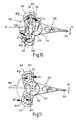
- Fig. 10 is a top plane view of an alternative embodiment (second embodiment) of the present invention in which an actuator 102 has two flat coils 162 and 172 of triangular shapes, different from those of the first embodiment shown in Figs. 4-6.
- the coil 162 (172) has a front portion 812 (822) and a rear portion 832 (842) which are inclined in an angular diverging relationship relatively to each other and in oppositely oriented diverging angular relationships relatively to a plane which includes an axis D2 of shaft 112 and a line D2' perpendicular to a line C2 which passes perpendicularly through the axis D2 and through the read/write head 152.
- the coil 162 produces a composite driving force S, as a total of component driving forces A2 and B2, respectively generated at portions 812 and 832 thereof.
- the coil 172 also produces a composite driving force S' as a total of component driving forces A2' and B2'.
- the driving forces S and S' are exactly perpendicular to a seek direction E2 and, for all practical purposes, are exactly balanced about a shaft 112. Therefore, vibration in a direction perpendicular the axis of rotation and which introduces frictional resistance to rotation of a bearing mounting the actuator 102 on a shaft 112, are reduced.
- the coils 162 and 172 are effectively perfectly-oriented because they never generate a component of force in a direction parallel to the seek direction E2. From a viewpoint of a rotating efficiency of the driving forces S and S', the efficiency in this embodiment is slightly less than the first embodiment. However, the actuator 102 has at least the potential of surpassing the performance of the first embodiment, as to over-all characteristics.
- the actuator 102 has the following advantages. (1) The actuator 102 affords increased space for reinforcing a the mounting and connection of the coils 162 and 172 to the coil surface mounting base 122b of the carriage 122, because the connecting surface areas therebetween are shifted toward the opposite side of the shaft 112 from head 152. (2) The actuator 102 is also smaller and better contoured than the actuators of the prior embodiments and thus provides increased space for attaching a flexible printed circuit board (FPC) 99, as shown in Fig. 5A, 5B, to the actuator 102. These advantages simplify the head actuator design.
- FPC flexible printed circuit board
- Fig. 11 is a top plane view of a further alternative embodiment (third embodiment) of the present invention in which the head actuator has pentagonally shaped flat coils. The effect is similar to that of the second embodiment shown in Fig. 10.
- the coil 163 in cooperation with magnet 183, generates driving forces A3 and B3 at portions 813 and 833, respectively, and the driving forces A3 and B3 are exactly perpendicular to the seek direction E3.
- the coil 173 also generates driving forces A3' and B3' at portions 823 and 843, respectively.
- the rotational driving force of the portion 833 is reduced by 15%, because the portion 833 is inclined relatively to radial direction and, further, the magnet 183 (i.e., extends beyond the outer, periphery of the magnet 183). If more driving force for rotation is required, the portion 833 should be arranged fully within (i.e., between) the magnets. Moveover, for optimum directions of driving forces, the portion 833 may be slightly shifted toward the outside as shown in Fig 11.
- Fig. 12A is an alternative embodiment (fourth embodiment) of the present invention in which a head actuator 104 has a trapezoidally shaped flat coil 23.
- a head actuator 104 has a trapezoidally shaped flat coil 23.
- two flat coils of the prior embodiments are replaced with one flat coil 23, which is formed substantially in a trapezoidal shape.
- the coil 23 generates respective driving forces at portions 231-234. These driving forces effectively are perfectly perpendicular to a seek direction E4 and balanced.
- a rotating efficiency is about 90% for the portions 231 and 232, and about 70% for the portions 233 and 234, and thereby the rotating efficiency average is about 80% which is a little lower than the above embodiments.
- this embodiment has a most excellent performance as to the vibration characteristic, because any component of force in the direction parallel to the seek direction E4 is very small. Moveover, resistance of the coil 23 is a little superior to the double-coil. Therefore, this embodiment should be selected when not an improved rotating efficiency, but rather an improved vibration characteristic is required.
- a reinforcement block 24 is shown in Fig. 12B and corresponds to the blocks 16a and 17a of Fig. 5B, discussed, supra.
- the block 24 is provided inside the coil 23 to support and reinforce the portions 233 and 234, because the coil 23 is large in size and the portions 233 and 234 are free.
- the reinforcement block 24 is made of an insulator, preferably a light-weight synthetic resin (for example, PPS, etc.,) having a high rigidity.
- the reinforcement block 24 has holes 25 for reducing weight without loss of rigidity.
- the coil 23 is wound around the reinforcement block 24.
- This reinforcement block 24 can be provided not only for the trapezoidal coil of the embodiment of Fig. 12A but also for the coils of the above embodiments.
- the presence of a reinforcement blocks does have an effect on the resonance frequency; for example, in the case of the first embodiment shown in Fig. 4, the resonance frequency is changed by about 10% depending on the existence, or not, of the reinforcement block.
- a magnet 27 has an outside circular edge 27a and an inside elliptical edge 27b. It is preferable to arrange the magnets so that a central segment 235 of the coil, extending between the coil portions 233 and 234, is not within the gap between the two magnets 27 but rather extends into the opening defined by the inside elliptical edge 27b (i.e., of each magnet of the pair of magnets 27).
- the central section 235 generates a driving force in the radial direction which does not cause a rotating force; thus, by so displacing the central segment 235 relative to the magnets 27 so as to be outside the gap between the magnets 27, the undesired radial driving force is reduced.
- the illustrated shapes of the coil 22 and magnets 27 are not limited to those shown and it is possible to arrange various modifications which achieve this same relationship.
- the magnet 27 has a generally elliptical interior edge and accordingly the cross-sectional width of the rear portions 233 and 234 decreases gradually for increasing distances from the shaft 114.
- Fig. 12A is superior to that of Fig. 4 in view of reduced assembly cost, because only one coil is required.
- Fig. 13 is an alternative embodiment of the present invention in which the head actuator has increased tolerance with respect to avoiding interference between disks and heads.
- a coil 165 generates a driving force S5 as a total of respective driving forces generated at portions 815 and 835
- a coil 175 also generates a driving force S5' as a total of driving forces generated at portions 825 and 845.
- the coil in the position of coil 165 of the actuator 105 of Fig. 13 would be more closely adjacent the disks 1 than the other coil 175, potentially interfering with the disks 1.
- the pair of coils 165 and 175 are rotationally displaced from the normal aligned relationship with the line D5 and instead are in aligned relationship with the line D5' which is rotationally displaced from the line D5 in a counterclockwise direction.
- This arrangement relatively increases the distance between the coil 165 and the circumference of the disks 1 without introducing any adverse decrease in the spacing between the coil 175 and the circumferential edge of the disks 1. This increases the margin of error and thus avoids interference between the disks 1 and the coil 165.
- the coils 165 and 175 are similar in shape to the second embodiment shown in Fig. 10.
- the driving forces S5 and S5' are perfectly parallel to the line C5' and, effectively, are perfectly balanced about the shaft 115. Therefore, although the 27 line C5' is not perfectly perpendicular to the seek direction E5, the frictional forces tending to oppose free rotation of the bearing, which mounts the actuator 105 on the shaft 114, are reduced while still maintaining a sufficient vibration characteristic for the actuator 105.
- the coils 165 and 175 are arranged with an inclination, it is easier to obtain perfectly balanced drive than with the other embodiments since the two coils 165 and 175 effectively can be disposed closer to a plane including the line D5' and passing through the axis of the shaft 115 than they could be aligned, instead, with a plane including the line D5, as shown by, for example, the distance between the coils 16 and 17 of the actuator 110 of Fig. 4 relatively to the line D1. It can also be seen that the axis of the actuator 10 in Fig. 4 is displaced farther from the circumference of the disks 1 whereas the rotated, or inclined, relationship of the coils 165 and 175 in Fig. 13 permits a closer spacing between the axis of shaft 115 and the circumference of the disks 1.
- the embodiment of Fig. 13 employs coils 165 and 175, similar to the coils 16 and 17 of Fig. 4, but the same are set at an inclined angle, as above discussed.
- the total driving forces of the coils 16 and 17 in the Fig. 4 embodiment are not perfectly perpendicular to the seek direction E1.
- the displacement to the inclined position of the coils 165 and 175 in the embodiment of Fig. 13, however, does not introduce any significant adverse changes in the vibration characteristic. This is because, whereas the driving force S5 of coil 165 is shifted so as to be less perpendicular to the seek direction E5 in Fig. 13 (relative to the corresponding driving force of coil 16 in Fig. 4), the driving force S5' of the coil 175 in Fig. 13 becomes more closely perpendicular to the seek direction E5 (as compared with the corresponding driving force of coil 17 in the Fig. 4 embodiment).
- Fig. 14 is a plot of a compliance-frequency characteristic of the head actuator of the Fig. 4 embodiment of the present invention.
- the compliance-frequency characteristic indicates an output amplitude (displacement or force) of a head for an input current of a head actuator at each frequency (Hz).
- the main resonance frequency 64 occurs at about 9.6 kHz (i.e., under 10 kHz) and therefore the compliance-frequency characteristic is almost linear, up to the resonance frequency 64.
- the resonance frequency of 29 the rigid body mode occurs near 5 kHz and is negligible, being of about 1-2 dB.
- the characteristic of the first embodiment shown in Fig. 4 is excellent.
- this first-occurring resonance frequency 61 is at about 2-4 kHz, but the first-occurring resonance frequency 64 in the first embodiment is at about 10 kHz.
- vibration of the rigid body mode at the resonance frequency 63 is suppressed remarkably.
- Such an effect is achieved by the arrangement of the coils as shown in Fig. 4. Therefore, it is possible to obtain a wide servo band and thereby excellent positioning accuracy of the actuator.
- Type 1 Prior art shown in Fig. 1
- Type 2 Present invention shown in Figs. 4-6 (low speed type)
- Type 3 Present invention shown in Figs.
- Type 4-6 is designed so as to obtain the same acceleration and seek time as the Type 1 using a single-coil actuator shown in Fig. 1.
- the electric power consumption of Type 2 is about 1/3 that of Type 1, achieved by an increase of coil volume and an optimization of the inertia moment.
- the Type 3 is designed so as to consume the same amount of electric power as the Type 1.
- the actuator of the Type 3 has the almost same structure as the Type 2, except for the diameter of the coil wire; therefore, the coil of the Type 3 has a resistance different from that of the Type 2.
- the Type 3 has a higher acceleration and thus a shorter seek time than the Types 1 and 2, and especially, an extraordinarily short seek time of as small as 5.8 ms, which is less than that of the Types 1 and 2 by 2.2 ms.
Landscapes
- Moving Of Heads (AREA)
- Micromachines (AREA)
Claims (23)
- Drehbewegungsspulen-Stellantrieb (10, 104) zum wahlweisen Positionieren eines Lese-/Schreibkopfes bezüglich eines rotierenden Plattenmediums (1) in einem Plattenlaufwerk, welcher Stellantrieb umfaßt:einen Wagen (12), welcher um eine Achse (0,02 bis 05) schwenkbar ist und einen Wagenarm (12a) zum Halten des Lese-/Schreibkopfes (15) aufweist;ein Paar Jochplatten (20, 20'), die in einer beabstandeten gegenseitigen Lage an dem Disklaufwerk befestigt sind;ein Paar Magneten (18, 18'; 27), die zwischen dem Paar von Jochplatten (20, 20') befestigt sind und jeweilige flache Flächen aufweisen, die senkrecht zu der Achse (0,02 bis 05) liegen und die einander mit einem dazwischen angeordneten Spalt zugewandt sind; undwenigstens eine flache Spule (16, 17; 23), welche an dem Wagen (12) angebracht und wenigstens teilweise in dem Spalt zwischen den flachen Flächen dieser Magneten (18, 18'; 27) angeordnet und diesen zugewandt ist, wobei die wenigstens eine.flache Spule (16, 17; 23) entlang eines Bewegungshubes relativ zu den flachen Flächen dieser Magneten (18, 18'; 27) bewegbar ist, dadurch gekennzeichnet, daß:die wenigstens eine flache Spule (16, 17; 23) so relativ zu den Magneten (18, 18'; 27) angeordnet ist, daß sie eine Antriebskraft in einer Richtung annähernd parallel zu einer ersten Linie (C1 bis C5) erzeugt, die senkrecht zu der Achse liegt und durch die Achse sowie den Lese-/Schreibkopf (15) hindurch verläuft.
- Stellantrieb nach Anspruch 1, bei welchem ein Paar flacher Spulen (16, 17) vorgesehen ist und die flachen Spulen (16, 17) dieses Paares symmetrisch bezüglich sowie auf einander abgewandten Seiten von einer Ebene angeordnet sind, die im wesentlichen sowohl die Achse als auch die erste Linie (C1 bis C3, C5) derart enthält, daß die flachen Spulen (16, 17) jeweilige Antriebskräfte erzeugen, die im wesentlichen entgegengesetzt ausgerichtet und symmetrisch bezüglich dieser Ebene sind.
- Stellantrieb nach Anspruch 1, bei welchem ein Paar flacher Spulen (16, 17) vorgesehen ist, und die flachen Spulen (16, 17) dieses Paares symmetrisch bezüglich sowie auf einander abgewandten Seiten von einer Ebene angeordnet sind, welche im wesentlichen die Achse (05) einschließt und winkelmäßig von der ersten Linie (C5) fort und zu einem Zentrum des rotierenden Plattenmediums (1) hin derart geneigt ist, daß die flachen Spulen (16, 17) jeweilige Antriebskräfte erzeugen, welche im wesentlichen entgegengesetzt zueinander ausgerichtet und symmetrisch bezüglich dieser Ebene sind.
- Stellantrieb nach Anspruch 1 oder 2, bei welchem die bzw. jede Spule (16, 17; 23) einen ersten Abschnitt (81, 82; 231, 232) umfaßt, welcher sich in einer Richtung annähernd senkrecht zu der ersten Linie (C1 bis C5) erstreckt.
- Stellantrieb nach Anspruch 4, bei welchem die oder jede Spule (16, 17; 23) ferner einen zweiten Abschnitt (83, 84; 233, 234) umfaßt, welcher von dem ersten Abschnitt beabstandet ist, wobei die ersten bzw. zweiten Abschnitte jeweils relativ näher zu bzw. weiter von dem rotierenden Plattenmedium (1) angeordnet sind.
- Stellantrieb nach Anspruch 5, bei welchem die zweiten Abschnitte (83, 84; 233, 234) der oder jeder flachen Spulen (16, 17; 23) sich in einer Richtung annähernd senkrecht zu der ersten Linie (C3) erstrecken.
- Stellantrieb nach Anspruch 5, bei welchem die zweiten Abschnitte (83, 84; 233, 234) der oder jeder flachen Spule (16, 17; 23) sich in einer Richtung erstrecken, die in einem Winkel von bis zu 30° von einer radialen Richtung relativ zu der Achse und senkrecht zu der ersten Linie (C1, C2, C5) geneigt ist.
- Stellantrieb nach Anspruch 5, 6 oder 7, bei welchem relativ zu einer die Achse enthaltenden und senkrecht zu der ersten Linie (C5) angeordneten Ebene die ersten Abschnitte dieser flachen Spulen (16, 17) mit einem vorgegebenen Versatz gegenüber der Ebene und an einer von dem Lese-/Schreibkopf (15) abgewandten Seite der Ebene angeordnet sind.
- Stellantrieb nach Anspruch 1 oder 2, bei welchem ein Paar flacher Spulen (16, 17) vorgesehen ist und jede flache Spule (16, 17) einen ersten Abschnitt (81, 82) und einen zweiten Abschnitt (83, 84) umfaßt, wobei die ersten und zweiten Abschnitte in einer winkelmäßig divergierenden Lage relativ zueinander und in einer entgegengesetzt divergierenden winkelmäßigen Lage relativ zu einer Ebene geneigt sind, die senkrecht zu der ersten Linie (C2) liegt und zwischen den ersten und zweiten Abschnitten angeordnet ist.
- Stellantrieb nach Anspruch 9, bei welchem diese Ebene gegenüber der Achse (02) entlang der ersten Linie (C2) in einer Richtung fort von dem Lese-/Schreibkopf (15) versetzt ist.
- Stellantrieb nach einem der vorangehenden Ansprüche, bei welchem jeder der Magneten (18, 18'; 23) vier Pole hat, die mit annähernd gleichen Zwischenräumen in einer Richtung des Bewegungshubes der bzw. jeder flachen Spule (16, 17) beabstandet sind.
- Stellantrieb nach einem der Ansprüche 1 bis 10, bei welchem ein Paar flacher Spulen (16, 17) vorgesehen ist und jeder Magnet (18, 18') einen entsprechenden zentralen Pol sowie ein entsprechendes Paar entgegengesetzter Endpole umfaßt, die durch den entsprechenden zentralen Pol integral miteinander verbunden sind und in Entsprechung zu dem Bewegungshub der flachen Spulen (16, 17) konfiguriert sind, wobei die Endpole eine gleiche Länge haben und der zentrale Pol im wesentlichen zweimal so lang wie jeder der Endpole ist.
- Stellantrieb nach einem der vorangehenden Ansprüche, bei welchem ein Paar flacher Spulen (16, 17) vorgesehen ist, und ferner umfassend:ein Paar Seitenjochblöcke (21, 21'), die jeweils gegenüberliegende Enden von einer Jochplatte (20, 20') mit entsprechenden gegenüberliegenden Enden der anderen Jochplatte (20, 20') dieses Paares verbinden; undein hinterer Jochblock (22), welcher einen zentralen Abschnitt dieser einen Jochplatte (20, 20') mit einem zentralen Abschnitt der anderen Jochplatte (20, 20') verbindet und außerhalb des Bewegungshubes der flachen Spulen (16, 17) verlagert ist.
- Stellantrieb (104) nach einem der Ansprüche 1 und 4 bis 8, bei welchem eine einzelne flache Spule (23) vorgesehen ist, die eine im wesentlichen trapezförmige Konfiguration hat, und wobei diese flache Spule (23) symmetrisch bezüglich einer ersten Ebene angeordnet ist, welche erste Ebene annähernd die Achse (04) und die erste Linie (C2) enthält.
- Stellantrieb (104) nach Anspruch 14, bei welchem die erste Ebene durch die Achse (04) hindurch geht und.von der ersten Linie (C4) zu einem Zentrum des rotierenden Plattenmediums (1) hin geneigt ist.
- Stellantrieb (104) nach Anspruch 14 oder 15, bei welchem jeder dieser Magnete (27) in der Form eines Bogens ausgebildet ist und eine veränderliche Breite in einer radialen Richtung hat, die relativ kleiner in einem zentralen Abschnitt desselben und relativ breiter in abgewandten Seitenabschnitten desselben ist.
- Stellantrieb (104) nach Anspruch 16, bei welchem jeder dieser Magneten (27) eine innere, halbelliptische Kante hat, welche die Achse (04) umgibt, sowie eine äußere halbkreisförmige Kante.
- Stellantrieb nach einem der Ansprüche 14 bis 17, ferner umfassend eine Basis mit einer im wesentlichen trapezförmigen Konfiguration, welche flache Spule (23) um die Basis herum gewickelt ist.
- Stellantrieb (104) nach Anspruch 18, bei welchem die Basis ein Loch hat.
- Stellantrieb nach Anspruch 1, bei welchem ein Paar flacher Spulen (16, 17) vorgesehen ist und diese Spulen (16, 17) mit dem Arm (12a) unter Verwendung eines Verbindungsmittels verbunden sind, welches eine vorgegebene Elastizität hat, um die Spulen (16, 17) mit dem Arm (12a) zu verbinden.
- Stellantrieb nach Anspruch 1, bei welchem ein Paar flacher Spulen (16, 17) vorgesehen ist, und:das Paar Jochplatten obere und untere Jochplatten (20, 20') umfaßt, die an festen Positionen in dem Plattenlaufwerk in einer beabstandeten gegenseitigen Lage in der ersten Richtung montiert sind und einen ersten Spalt zwischen sich definieren;das Paar von Magneten obere und untere Magneten (18, 18') umfaßt, die in festen Positionen zwischen und jeweils anliegend an dem Paar oberer und unterer Jochplatten (20, 20') montiert ist, wobei die oberen und unteren Magneten (18, 18') zugeordnete flache Flächen aufweisen, die senkrecht zu der Wagenachse und in paralleler, beabstandeter .gegenseitiger Lage in der ersten Richtung angeordnet sind, und einen zweiten Spalt zwischen sich definieren; und wobei das Paar flacher Spulen (16, 17) umfaßt:eine erste flache Spule (16, 17), die an dem Wagen (12) angebracht ist und entsprechende obere und untere Flächen hat, die jeweils in oberen und unteren gemeinsamen Ebenen senkrecht zu der Wagenachse (0) liegen, wobei wenigstens Abschnitte der flachen Spule (16, 17) innerhalb des zweiten Spaltes und in einer beabstandeten, zugewandten Lage relativ zu den entsprechenden flachen Flächen der oberen und unteren Magnete (18, 18') angeordnet sind, wobei die flache Spule (16, 17) in einer gemeinsamen Schwenkbewegung mit dem Wagen (12) um die Wagenachse (0) und dadurch .entlang eines Bewegungshubes relativ zu den entsprechenden flachen Flächen der oberen und unteren Magneten (18, 18') bewegbar ist, wobei die erste flache Spule (16, 17) einen elektrischen, durchfließenden Strom führt und ein magnetisches Feld erzeugt, sowie, im Zusammenwirken mit entsprechenden Magnetfeldern der oberen und unteren Magneten (18, 18') eine Antriebskraft erzeugt, die im wesentlichen parallel zu einer ersten Linie ist, welche senkrecht durch die Wagenachse (0) hindurch und zu dem Lese-/Schreibkopf (15) hin verläuft, um wahlweise den Wagen zu einer Schwenkbewegung um die Achse (0) anzutreiben; undeine zweite, an dem Wagen (12) angebrachte flache Spule (16, 17) mit einer zu der der ersten flachen Spule (16, 17) komplementären Konfiguration; wobei die ersten und zweiten flachen Spulen (16, 17) in einer Querrichtung von einer die Achse und die erste Linie enthaltenden Ebene entgegengesetzt verlagert sind, wobei die ersten und zweiten flachen Spulen (16, 17) gemeinsam einen hindurchfließenden elektrischen Strom führen und, im Zusammenwirken mit entsprechenden magnetischen Feldern der oberen und unteren Magneten (18, 18') jeweilige magnetische Felder erzeugen, welche jeweilige entgegengesetzt ausgerichtete erste und zweite Antriebskräfte produzieren, die im wesentlichen parallel zu und auf jeweiligen abgewandten Seiten von der ersten Linie liegen und welche sich in einem additiven Verhältnis verbinden, um den Wagen (12) wahlweise zu einer Schwenkbewegung um die Achse (0) anzutreiben.
- Stellantrieb nach Anspruch 21, bei welchem:das Plattenlaufwerk eine rotierende Platte mit einer Aufzeichnungsmediumoberfläche und einer kreisförmigen Peripherie aufnimmt und zu einer Drehung um eine Plattendrehachse antreibt, die gegenüber der Wagenachse (0) um eine Distanz verlagert ist, die im wesentlichen einer Distanz von der Wagenachse (0) zu dem Lese-/Schreibkopf (15) entspricht, wobei die Bewegung des Wagens (12) über den Bewegungshub desselben entsprechend den Lese-/Schreibkopf (15) über einen im wesentlichen radialen Lese-/Schreibkopf-Suchbewegungshub bewegt, welcher sich zwischen einer inneren Position neben der Plattenachse und einer äußeren Position neben der Peripherie der Platte erstreckt; unddie erste Linie senkrecht durch die Wagenachse (0) und durch den Lese-/Schreibkopf (15) hindurch verläuft, und zwar im wesentlichen mit der Wagenarmmittellinie zusammenfallend.
- Stellantrieb nach Anspruch 21, bei welchem das Plattenlaufwerk eine rotierende Platte mit einer Aufzeichnungsmediumoberfläche und einer kreisförmigen Peripherie aufnimmt und zu einer Drehung um eine Plattendrehachse antreibt, die gegenüber der Wagenachse (0) um eine Distanz verlagert ist, die im wesentlichen einer Distanz von der Wagenachse (0) zu dem Lese-/Schreibkopf (15) entspricht, wobei die Bewegung des Wagens über den Bewegungshub desselben entsprechend den Lese-/Schreibkopf (15) über einen im wesentlichen radialen Lese-/Schreibkopf-Suchbewegungshub bewegt, der sich zwischen einer inneren Position neben der Plattenachse und einer äußeren Position neben der Peripherie der Platte erstreckt; und
wobei die erste Linie senkrecht durch die Wagenachse (0) hindurch verläuft und im Winkel relativ zu der Wagenarmmittellinie in einer Richtung entlang dem Lese-/Schreibkopf-Suchbewegungshub von der Plattenperipherie aus und zu der Plattenachse hin geneigt ist.
Applications Claiming Priority (3)
| Application Number | Priority Date | Filing Date | Title |
|---|---|---|---|
| JP10642495A JP3257923B2 (ja) | 1995-04-28 | 1995-04-28 | ディスク装置 |
| JP106424/95 | 1995-04-28 | ||
| JP10642495 | 1995-04-28 |
Publications (2)
| Publication Number | Publication Date |
|---|---|
| EP0740300A1 EP0740300A1 (de) | 1996-10-30 |
| EP0740300B1 true EP0740300B1 (de) | 2002-08-14 |
Family
ID=14433286
Family Applications (1)
| Application Number | Title | Priority Date | Filing Date |
|---|---|---|---|
| EP96106431A Expired - Lifetime EP0740300B1 (de) | 1995-04-28 | 1996-04-24 | Kopfbetätigungsorgan für Plattenantriebssystem |
Country Status (6)
| Country | Link |
|---|---|
| US (1) | US5764441A (de) |
| EP (1) | EP0740300B1 (de) |
| JP (1) | JP3257923B2 (de) |
| KR (1) | KR100206034B1 (de) |
| CN (1) | CN1137484C (de) |
| DE (1) | DE69622914T2 (de) |
Families Citing this family (23)
| Publication number | Priority date | Publication date | Assignee | Title |
|---|---|---|---|---|
| US5748575A (en) * | 1996-03-05 | 1998-05-05 | Intellectual Science And Technology, Inc. | Information processing apparatus having a multitasking function with one or more optical discs |
| JP2904177B2 (ja) * | 1997-03-21 | 1999-06-14 | 日本電気株式会社 | 磁気ディスク装置のヘッド位置決め機構及びその駆動制御方法 |
| DE19882619T1 (de) * | 1997-09-23 | 2000-07-27 | Seagate Technology | Verbesserter Plattenlaufwerk-Drehbetätiger |
| US6115215A (en) * | 1998-02-24 | 2000-09-05 | Seagate Technology, Inc. | Balanced actuator which accesses separate disc assemblies |
| JPH11273279A (ja) | 1998-03-20 | 1999-10-08 | Fujitsu Ltd | ディスク装置及びヘッドキャリッジ装置 |
| US6535357B1 (en) * | 1998-06-05 | 2003-03-18 | Seagate Technology Llc | Latch for disc drives |
| US6226156B1 (en) * | 1998-07-17 | 2001-05-01 | Quantum Corp. | Magnetic read/write head actuator assembly having an actuator motor with dual windings |
| US6104581A (en) * | 1998-10-05 | 2000-08-15 | International Business Machines Corporation | Dual coil rotary actuator |
| JP2001135055A (ja) * | 1999-11-01 | 2001-05-18 | Hitachi Ltd | 磁気ディスク装置 |
| US6639761B1 (en) | 1999-12-02 | 2003-10-28 | Seagate Technology Llc | Micro-actuator damping and humidity protection |
| US6633457B1 (en) * | 2000-07-25 | 2003-10-14 | Data Storage Institute | Actuator assembly with orthogonal force generation |
| US6768614B2 (en) * | 2001-01-23 | 2004-07-27 | Maxtor Corporation | Positioner for precisely moving an e-block of a disk drive |
| US6947260B2 (en) * | 2002-11-18 | 2005-09-20 | Hitachi Global Storage Technologies Netherlands B.V. | System and method of damping vibration on coil supports in high performance disk drives with rotary actuators |
| US6816343B1 (en) | 2003-01-31 | 2004-11-09 | Western Digital Technologies, Inc. | Disk drive including an actuator coil with side segments equally overlapping inner and outer magnet sets |
| US6816342B1 (en) | 2003-01-31 | 2004-11-09 | Western Digital Technologies, Inc. | Disk drive including a pair of actuator coils each with a radial segment generally perpendicular to inner and outer segments and overlapping with inner and outer magnets |
| US6906897B1 (en) | 2003-02-28 | 2005-06-14 | Western Digital Technologies, Inc. | Disk drive including an actuator main coil and an actuator secondary coil with a lateral segment and method of operating same |
| US7088556B1 (en) * | 2003-06-30 | 2006-08-08 | Maxtor Corporation | Positioner for a disk drive that offsets the resultant force at the actuator hub to precisely position a data transducer |
| KR100537515B1 (ko) * | 2003-11-22 | 2005-12-19 | 삼성전자주식회사 | 동적 특성이 향상된 액츄에이터와 이를 구비한 디스크드라이브 |
| JP2005243177A (ja) * | 2004-02-27 | 2005-09-08 | Fujitsu Ltd | 磁気ディスク装置 |
| US7239486B2 (en) * | 2004-06-30 | 2007-07-03 | Hitachi Global Storage Technologies Netherlands B.V. | System and apparatus for reducing off-track gain for a disk drive actuator |
| CN100363983C (zh) * | 2005-12-29 | 2008-01-23 | 深圳易拓科技有限公司 | 硬盘驱动器的安装方法及专用于该方法的磁块和夹具 |
| DE102006020730A1 (de) * | 2006-05-04 | 2007-11-08 | Deutsche Thomson Ohg | Schwingarm-Aktuator für mehrere Bewegungsrichtungen |
| US8068309B2 (en) * | 2008-08-27 | 2011-11-29 | Seagate Technology Llc | Vibration damper for actuator assembly |
Family Cites Families (7)
| Publication number | Priority date | Publication date | Assignee | Title |
|---|---|---|---|---|
| US4620252A (en) * | 1981-05-01 | 1986-10-28 | Iomega Corporation | Symmetrical coil actuator for a magnetic disk drive |
| US5041935A (en) * | 1988-08-17 | 1991-08-20 | Fujitsu Limited | Rotary actuator for positioning magnetic heads in a disk drive |
| JPH03173343A (ja) * | 1989-11-29 | 1991-07-26 | Sony Corp | 可動コイル型アクチュエータ |
| US5267110A (en) * | 1991-03-19 | 1993-11-30 | International Business Machines Corporation | Rotary actuator for a direct access storage device |
| US5233493A (en) * | 1991-04-15 | 1993-08-03 | Seagate Technology, Inc. | Notched arcuate magnet for rotary actuator |
| US5459359A (en) * | 1992-04-30 | 1995-10-17 | Hitachi Metals, Ltd. | Swing-type actuator |
| JP2821723B2 (ja) * | 1993-02-18 | 1998-11-05 | 株式会社日立製作所 | 回転形情報記録再生装置 |
-
1995
- 1995-04-28 JP JP10642495A patent/JP3257923B2/ja not_active Expired - Fee Related
-
1996
- 1996-04-23 US US08/636,802 patent/US5764441A/en not_active Expired - Lifetime
- 1996-04-24 EP EP96106431A patent/EP0740300B1/de not_active Expired - Lifetime
- 1996-04-24 DE DE69622914T patent/DE69622914T2/de not_active Expired - Fee Related
- 1996-04-26 CN CNB961062738A patent/CN1137484C/zh not_active Expired - Fee Related
- 1996-04-27 KR KR1019960013279A patent/KR100206034B1/ko not_active Expired - Fee Related
Also Published As
| Publication number | Publication date |
|---|---|
| JPH08306142A (ja) | 1996-11-22 |
| KR100206034B1 (ko) | 1999-07-01 |
| US5764441A (en) | 1998-06-09 |
| EP0740300A1 (de) | 1996-10-30 |
| DE69622914T2 (de) | 2002-12-05 |
| KR960038756A (ko) | 1996-11-21 |
| CN1149744A (zh) | 1997-05-14 |
| CN1137484C (zh) | 2004-02-04 |
| JP3257923B2 (ja) | 2002-02-18 |
| DE69622914D1 (de) | 2002-09-19 |
Similar Documents
| Publication | Publication Date | Title |
|---|---|---|
| US5764441A (en) | Head actuator having reduced and controlled vibration characteristics for high speed disk drive systems | |
| US5101305A (en) | Disk drive device including a V-shaped air filter | |
| US6816343B1 (en) | Disk drive including an actuator coil with side segments equally overlapping inner and outer magnet sets | |
| US6980401B1 (en) | Head stack and actuator arm assemblies including a bobbin to stiffen the coil portion of an actuator of a hard disk drive and disk drives including the same | |
| US6961218B1 (en) | Disk drive actuator arm assembly having one or more slotted actuator arms | |
| KR100236608B1 (ko) | 헤드액츄에이터 | |
| US6879466B1 (en) | Disk drive including an actuator with a constrained layer damper disposed upon an actuator body lateral surface | |
| US5014146A (en) | Magnetic head mounting arm having asymmetrical configuration | |
| US5566375A (en) | Magnetic disk drive having voice coil motor for moving a carriage and rocking mechanism for locking the carriage | |
| US6775106B1 (en) | E-block having improved resonance characteristics and improved fragility | |
| US4835643A (en) | Disk drive head actuator coil | |
| CN1321418C (zh) | 头支承装置及使用该装置的盘装置 | |
| US7016157B1 (en) | E-block having improved resonance characteristics and improved fragility | |
| Aruga et al. | High-speed orthogonal power effect actuator for recording at over 10000 TPI | |
| US20030165033A1 (en) | Head support device and recording regenerator having this head support device | |
| US7675714B1 (en) | Stiffened voice coil for reduction of tracking errors in a disk drive | |
| US7038886B1 (en) | Positioner for precisely moving an E-block of a disk drive | |
| US9368140B2 (en) | Actuator assembly and rotating disk storage device with efficient voice coil shape | |
| US20030053261A1 (en) | Bandwidth disc drive actuator | |
| US20020057631A1 (en) | Fringing field focus motor and mechanism for optical disk drive | |
| EP0518632B1 (de) | Magnetischer Plattenspeicher | |
| US5105321A (en) | Disk drive including flexible print board and back tension regulating piece | |
| US5875076A (en) | Asymmetrical actuator structure for recording-reproducing apparatus | |
| US7040004B2 (en) | Method of making a data storage device having an actuator with a rail | |
| EP0246375B1 (de) | Kopf/Arm-Zusammenbau und rotierender Zugangsmechanismus für einen Plattenspeicher |
Legal Events
| Date | Code | Title | Description |
|---|---|---|---|
| PUAI | Public reference made under article 153(3) epc to a published international application that has entered the european phase |
Free format text: ORIGINAL CODE: 0009012 |
|
| AK | Designated contracting states |
Kind code of ref document: A1 Designated state(s): DE FR GB |
|
| 17P | Request for examination filed |
Effective date: 19960923 |
|
| 17Q | First examination report despatched |
Effective date: 20000615 |
|
| GRAG | Despatch of communication of intention to grant |
Free format text: ORIGINAL CODE: EPIDOS AGRA |
|
| GRAG | Despatch of communication of intention to grant |
Free format text: ORIGINAL CODE: EPIDOS AGRA |
|
| GRAH | Despatch of communication of intention to grant a patent |
Free format text: ORIGINAL CODE: EPIDOS IGRA |
|
| GRAH | Despatch of communication of intention to grant a patent |
Free format text: ORIGINAL CODE: EPIDOS IGRA |
|
| GRAA | (expected) grant |
Free format text: ORIGINAL CODE: 0009210 |
|
| AK | Designated contracting states |
Kind code of ref document: B1 Designated state(s): DE FR GB |
|
| REG | Reference to a national code |
Ref country code: GB Ref legal event code: FG4D |
|
| REF | Corresponds to: |
Ref document number: 69622914 Country of ref document: DE Date of ref document: 20020919 |
|
| PG25 | Lapsed in a contracting state [announced via postgrant information from national office to epo] |
Ref country code: FR Free format text: LAPSE BECAUSE OF FAILURE TO SUBMIT A TRANSLATION OF THE DESCRIPTION OR TO PAY THE FEE WITHIN THE PRESCRIBED TIME-LIMIT Effective date: 20030221 |
|
| ET | Fr: translation filed | ||
| PLBE | No opposition filed within time limit |
Free format text: ORIGINAL CODE: 0009261 |
|
| STAA | Information on the status of an ep patent application or granted ep patent |
Free format text: STATUS: NO OPPOSITION FILED WITHIN TIME LIMIT |
|
| 26N | No opposition filed |
Effective date: 20030515 |
|
| PGFP | Annual fee paid to national office [announced via postgrant information from national office to epo] |
Ref country code: FR Payment date: 20090417 Year of fee payment: 14 Ref country code: DE Payment date: 20090420 Year of fee payment: 14 |
|
| PGFP | Annual fee paid to national office [announced via postgrant information from national office to epo] |
Ref country code: GB Payment date: 20090422 Year of fee payment: 14 |
|
| REG | Reference to a national code |
Ref country code: GB Ref legal event code: 732E Free format text: REGISTERED BETWEEN 20091112 AND 20091118 |
|
| REG | Reference to a national code |
Ref country code: FR Ref legal event code: TP |
|
| GBPC | Gb: european patent ceased through non-payment of renewal fee |
Effective date: 20100424 |
|
| REG | Reference to a national code |
Ref country code: FR Ref legal event code: ST Effective date: 20101230 |
|
| PG25 | Lapsed in a contracting state [announced via postgrant information from national office to epo] |
Ref country code: DE Free format text: LAPSE BECAUSE OF NON-PAYMENT OF DUE FEES Effective date: 20101103 |
|
| PG25 | Lapsed in a contracting state [announced via postgrant information from national office to epo] |
Ref country code: GB Free format text: LAPSE BECAUSE OF NON-PAYMENT OF DUE FEES Effective date: 20100424 |
|
| PG25 | Lapsed in a contracting state [announced via postgrant information from national office to epo] |
Ref country code: FR Free format text: LAPSE BECAUSE OF FAILURE TO SUBMIT A TRANSLATION OF THE DESCRIPTION OR TO PAY THE FEE WITHIN THE PRESCRIBED TIME-LIMIT Effective date: 20100430 |