EP0740072B1 - Méthode et circuit pour détecter la présence d'une etincelle dans un moteur à combustion interne - Google Patents
Méthode et circuit pour détecter la présence d'une etincelle dans un moteur à combustion interne Download PDFInfo
- Publication number
- EP0740072B1 EP0740072B1 EP95830169A EP95830169A EP0740072B1 EP 0740072 B1 EP0740072 B1 EP 0740072B1 EP 95830169 A EP95830169 A EP 95830169A EP 95830169 A EP95830169 A EP 95830169A EP 0740072 B1 EP0740072 B1 EP 0740072B1
- Authority
- EP
- European Patent Office
- Prior art keywords
- voltage signal
- spark
- circuit
- voltage
- logic level
- Prior art date
- Legal status (The legal status is an assumption and is not a legal conclusion. Google has not performed a legal analysis and makes no representation as to the accuracy of the status listed.)
- Expired - Lifetime
Links
Images


Classifications
-
- H—ELECTRICITY
- H01—ELECTRIC ELEMENTS
- H01T—SPARK GAPS; OVERVOLTAGE ARRESTERS USING SPARK GAPS; SPARKING PLUGS; CORONA DEVICES; GENERATING IONS TO BE INTRODUCED INTO NON-ENCLOSED GASES
- H01T13/00—Sparking plugs
- H01T13/58—Testing
- H01T13/60—Testing of electrical properties
-
- F—MECHANICAL ENGINEERING; LIGHTING; HEATING; WEAPONS; BLASTING
- F02—COMBUSTION ENGINES; HOT-GAS OR COMBUSTION-PRODUCT ENGINE PLANTS
- F02P—IGNITION, OTHER THAN COMPRESSION IGNITION, FOR INTERNAL-COMBUSTION ENGINES; TESTING OF IGNITION TIMING IN COMPRESSION-IGNITION ENGINES
- F02P17/00—Testing of ignition installations, e.g. in combination with adjusting; Testing of ignition timing in compression-ignition engines
- F02P17/12—Testing characteristics of the spark, ignition voltage or current
-
- G—PHYSICS
- G01—MEASURING; TESTING
- G01R—MEASURING ELECTRIC VARIABLES; MEASURING MAGNETIC VARIABLES
- G01R29/00—Arrangements for measuring or indicating electric quantities not covered by groups G01R19/00 - G01R27/00
- G01R29/02—Measuring characteristics of individual pulses, e.g. deviation from pulse flatness, rise time or duration
- G01R29/027—Indicating that a pulse characteristic is either above or below a predetermined value or within or beyond a predetermined range of values
- G01R29/0273—Indicating that a pulse characteristic is either above or below a predetermined value or within or beyond a predetermined range of values the pulse characteristic being duration, i.e. width (indicating that frequency of pulses is above or below a certain limit)
Definitions
- the present invention relates to a method for detecting the presence of a spark in an electronic ignition device for an internal combustion motor and to a related circuit.
- the technical problem underlying the present invention is to provide a method and related circuit for correctly and accurately detecting a spark in an electronic ignition device of an internal combustion motor.
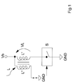
- reference number 1 indicates as a whole and diagrammatically a circuit provided in accordance with the present invention for detecting the presence of a spark produced by means of a spark coil L inserted in an electronic ignition device of an internal combustion motor.
- the coil L comprises a primary circuit L' inserted between a power supply voltage generator Vb and a controlled switch S and a secondary circuit L".
- the circuit 1 also comprises a first input block I provided e.g. by means of a resistive divider (R1,R2) having an input terminal connected to the primary circuit L' of the coil L and an output terminal.
- R1,R2 resistive divider
- This circuit comprises also a comparator C with hysteresis having a first input terminal connected to the output terminal of the input block I.
- the comparator also comprises a second and a third input terminals kept respectively at a first U1 and a second U2 reference voltage.
- this first reference voltage U1 and second reference voltage U2 represent respectively the upper and lower thresholds of the comparator C.
- the second reference voltage U2 is obtained preferably by means of a resistive divider (R3,R4) connected to the supply voltage generator Vb.
- the comparator C also comprises a low-pass filter FB.
- the circuit 1 also comprises a second signalling block SEG having an input terminal connected to an output terminal of the comparator C and an output terminal which is an output terminal OUT in the drawing of the circuit 1.
- This second signalling block SEG comprises in turn a counter CON having a first input terminal connected to the output terminal of the comparator C and a second input terminal receiving a timing signal Ck.
- the counter CON has an output connected to an input of a digital comparator CD having a second input terminal connected to a memory element M in which is memorized a binary reference value B.
- the comparator C with hysteresis compares this voltage U with the upper threshold U1 and lower threshold U2.
- a voltage Vc which is at a high logic level when the voltage U exceeds the threshold value U1.
- the voltage Vc by means of the filter FB keeps this logic level high for the entire duration of the transient until the voltage U falls below the lower threshold value U2 as shown in FIG. 4.
- the duration of the voltage Vc is proportional to the duration of the overvoltage created on the primary circuit L' of the coil L when the controlled switch S opens.
Landscapes
- Engineering & Computer Science (AREA)
- Chemical & Material Sciences (AREA)
- Combustion & Propulsion (AREA)
- Mechanical Engineering (AREA)
- General Engineering & Computer Science (AREA)
- Physics & Mathematics (AREA)
- General Physics & Mathematics (AREA)
- Ignition Installations For Internal Combustion Engines (AREA)
Claims (5)
- Méthode de détection de la présence d'une étincelle produite par une bobine d'excitation (L) ayant un circuit primaire (L') connecté à un générateur de tension d'alimentation (Vb) et un circuit secondaire (L"), ladite bobine d'excitation (L) étant insérée dans un dispositif d'allumage électronique d'un moteur à combustion interne et ladite méthode étant caractérisée en ce qu'elle comprend les phases de :générer un premier signal de tension (U) proportionnel à une tension (VL) présente sur le circuit primaire de la bobine d'excitation (L);comparer ce premier signal de tension (U) avec une première (U1) valeur de seuil supérieure et générer en réponse un deuxième signal de tension (Vc) à un premier niveau logique lorsque le premier signal de tension dépasse la première (U1) valeur de seuil supérieure;maintenir ledit deuxième signal de tension (Vc) au premier niveau logique;comparer ledit premier signal de tension (U) avec une deuxième (U2) valeur de seuil inférieure proportionnelle à la tension d'alimentation (Vb) et générer en réponse un deuxième signal de tension (Vc) à un deuxième niveau logique lorsque le premier signal de tension descend au-dessous de la deuxième (U2) valeur de seuil inférieure;détecter la durée temporelle du deuxième signal de tension (Vc); etsignaler la présence d'étincelle sur l'enroulement secondaire si cette durée temporelle dépasse une valeur (B) de référence.
- Méthode selon la revendication 1, caractérisée en ce que la phase de détection de la durée temporelle du deuxième signal de tension (Vc) comprend la phase de :générer une valeur (A) proportionnelle à la durée temporelle du signal de tension digital (Vc);
- Méthode selon la revendication 2, caractérisée en ce que la phase de signalation de la présence d'étincelle comprend la phase de:produire une valeur de sortie (OUT) à un niveau logique élevé lorsque la durée temporelle du deuxième signal de tension (Vc) dépasse une valeur (B) de référence.
- Méthode selon la revendication 1, caractérisée en ce que la première (U1) valeur de seuil supérieure est constante.
- Méthode selon la revendication 1, caractérisée en ce que le premier niveau logique est haut et le deuxième niveau logique est bas.
Priority Applications (3)
| Application Number | Priority Date | Filing Date | Title |
|---|---|---|---|
| EP95830169A EP0740072B1 (fr) | 1995-04-28 | 1995-04-28 | Méthode et circuit pour détecter la présence d'une etincelle dans un moteur à combustion interne |
| DE69527702T DE69527702T2 (de) | 1995-04-28 | 1995-04-28 | Methode und Schaltung zur Erkennung eines Zündfunkens in einer inneren Brennkraftmaschine |
| US08/639,779 US5790039A (en) | 1995-04-28 | 1996-04-29 | Method for detecting the presence of a spark in an electronic ignition system used with an internal combustion engine |
Applications Claiming Priority (1)
| Application Number | Priority Date | Filing Date | Title |
|---|---|---|---|
| EP95830169A EP0740072B1 (fr) | 1995-04-28 | 1995-04-28 | Méthode et circuit pour détecter la présence d'une etincelle dans un moteur à combustion interne |
Publications (2)
| Publication Number | Publication Date |
|---|---|
| EP0740072A1 EP0740072A1 (fr) | 1996-10-30 |
| EP0740072B1 true EP0740072B1 (fr) | 2002-08-07 |
Family
ID=8221908
Family Applications (1)
| Application Number | Title | Priority Date | Filing Date |
|---|---|---|---|
| EP95830169A Expired - Lifetime EP0740072B1 (fr) | 1995-04-28 | 1995-04-28 | Méthode et circuit pour détecter la présence d'une etincelle dans un moteur à combustion interne |
Country Status (3)
| Country | Link |
|---|---|
| US (1) | US5790039A (fr) |
| EP (1) | EP0740072B1 (fr) |
| DE (1) | DE69527702T2 (fr) |
Cited By (1)
| Publication number | Priority date | Publication date | Assignee | Title |
|---|---|---|---|---|
| TWI463144B (zh) * | 2012-08-17 | 2014-12-01 | Prolific Technology Inc | 可偵測突波訊號特性之突波偵測裝置 |
Families Citing this family (13)
| Publication number | Priority date | Publication date | Assignee | Title |
|---|---|---|---|---|
| JP3228159B2 (ja) * | 1996-12-06 | 2001-11-12 | トヨタ自動車株式会社 | エンジンの点火プラグ検査方法 |
| WO1999007995A1 (fr) * | 1997-08-12 | 1999-02-18 | Siemens Aktiengesellschaft | Dispositif de mesure et de diagnostic pour le systeme d'allumage d'un moteur a combustion interne |
| US6278278B1 (en) | 1998-08-12 | 2001-08-21 | Siemens Aktiengesellschaft | Measuring and diagnostic device for an ignition system of an internal combustion engine |
| DE60015711T2 (de) | 2000-01-27 | 2005-11-24 | Stmicroelectronics S.R.L., Agrate Brianza | Elektronische Zündungseinheit mit Beschränkung der Spannung an eine Anschluss der Zündungspulenprimärwicklung |
| US6492818B1 (en) * | 2000-11-06 | 2002-12-10 | Cummins, Inc. | Apparatus and method for determining component fault conditions as a function of primary coil voltage in a capacitive discharge ignition system |
| AU2002346211B2 (en) * | 2001-06-27 | 2008-06-12 | Sony Corporation | Integrated circuit device, information processing device, information recording device memory management method, mobile terminal device, semiconductor integrated circuit device, and communication method using mobile terminal device |
| DE102006054016A1 (de) * | 2006-11-16 | 2008-05-21 | Bayerische Motoren Werke Ag | Elektronische Überwachung des Bordnetzes eines Kraftfahrzeugs auf Spannungsspitzen oder Spannungseinbrüche |
| ITMI20130002A1 (it) * | 2013-01-03 | 2014-07-04 | St Microelectronics Srl | Apparato di controllo di una candela di accensione e sistema di accensione elettronica di motori con protezione da secondario aperto |
| CN103324226A (zh) * | 2013-06-28 | 2013-09-25 | 成都汉康信息产业有限公司 | 过压保护型遥测终端机 |
| JP5901718B1 (ja) * | 2014-09-24 | 2016-04-13 | 三菱電機株式会社 | 内燃機関制御装置 |
| KR102403994B1 (ko) | 2016-06-21 | 2022-05-31 | 몰렉스 엘엘씨 | 전기 스파크 검출을 위한 시스템 및 방법 |
| CN106655084A (zh) * | 2016-10-25 | 2017-05-10 | 上海联影医疗科技有限公司 | 一种高压发生器打火保护装置及方法 |
| SE542389C2 (en) * | 2018-09-04 | 2020-04-21 | Sem Ab | An ignition system and method controlling spark ignited combustion engines |
Citations (1)
| Publication number | Priority date | Publication date | Assignee | Title |
|---|---|---|---|---|
| EP0654604A1 (fr) * | 1993-11-22 | 1995-05-24 | Magneti Marelli France | Procédé et dispositif d'allumage à bobine avec des décharges additionnelles pour diagnostics |
Family Cites Families (11)
| Publication number | Priority date | Publication date | Assignee | Title |
|---|---|---|---|---|
| US4377785A (en) * | 1979-07-06 | 1983-03-22 | Nippon Soken, Inc. | Device for diagnosing ignition system for use in internal combustion engine |
| IT1119341B (it) * | 1979-08-02 | 1986-03-10 | Cselt Centro Studi Lab Telecom | Analizzatore di tensioni impulsive |
| US4918389A (en) * | 1988-06-03 | 1990-04-17 | Robert Bosch Gmbh | Detecting misfiring in spark ignition engines |
| DE3907616A1 (de) * | 1989-03-09 | 1990-09-20 | Bosch Gmbh Robert | Schaltungsanordnung zur messung der primaerspannung einer zuendspule |
| US4913123A (en) * | 1989-03-23 | 1990-04-03 | Ford Motor Company | Ignition timing system with feedback correction |
| DE4009451C2 (de) * | 1989-03-27 | 1995-02-16 | Mitsubishi Electric Corp | Zündvorrichtung für eine Brennkraftmaschine |
| DE4020986C2 (de) * | 1990-07-02 | 1998-09-03 | Telefunken Microelectron | Elektronisches Zündsystem für eine Brennkraftmaschine |
| FR2676506B1 (fr) * | 1991-05-15 | 1993-09-03 | Siemens Automotive Sa | Procede et dispositif de detection de rates d'allumage dans un cylindre de moteur a combustion interne et leur application. |
| US5283527A (en) * | 1991-06-28 | 1994-02-01 | Ford Motor Company | Methods and apparatus for detecting short circuited secondary coil winding via monitoring primary coil winding |
| US5446385A (en) * | 1992-10-02 | 1995-08-29 | Robert Bosch Gmbh | Ignition system for internal combustion engines |
| US5534781A (en) * | 1994-08-15 | 1996-07-09 | Chrysler Corporation | Combustion detection via ionization current sensing for a "coil-on-plug" ignition system |
-
1995
- 1995-04-28 EP EP95830169A patent/EP0740072B1/fr not_active Expired - Lifetime
- 1995-04-28 DE DE69527702T patent/DE69527702T2/de not_active Expired - Fee Related
-
1996
- 1996-04-29 US US08/639,779 patent/US5790039A/en not_active Expired - Lifetime
Patent Citations (1)
| Publication number | Priority date | Publication date | Assignee | Title |
|---|---|---|---|---|
| EP0654604A1 (fr) * | 1993-11-22 | 1995-05-24 | Magneti Marelli France | Procédé et dispositif d'allumage à bobine avec des décharges additionnelles pour diagnostics |
Cited By (1)
| Publication number | Priority date | Publication date | Assignee | Title |
|---|---|---|---|---|
| TWI463144B (zh) * | 2012-08-17 | 2014-12-01 | Prolific Technology Inc | 可偵測突波訊號特性之突波偵測裝置 |
Also Published As
| Publication number | Publication date |
|---|---|
| DE69527702D1 (de) | 2002-09-12 |
| DE69527702T2 (de) | 2002-12-05 |
| US5790039A (en) | 1998-08-04 |
| EP0740072A1 (fr) | 1996-10-30 |
Similar Documents
| Publication | Publication Date | Title |
|---|---|---|
| EP0740072B1 (fr) | Méthode et circuit pour détecter la présence d'une etincelle dans un moteur à combustion interne | |
| JPH088748B2 (ja) | 満充電検出回路 | |
| US7525783B2 (en) | Monitoring method for an actuator and corresponding driver circuit | |
| KR960020286A (ko) | 링트립 판정회로 | |
| JP2002089426A (ja) | 内燃機関の失火検出装置 | |
| US4478200A (en) | Electronic ignition system for internal combustion engine capable of supplying electric power to auxiliary unit | |
| US6367318B1 (en) | Multicharge ignition system having combustion feedback for termination | |
| KR100297673B1 (ko) | 점화제어시스템 | |
| EP0183223B1 (fr) | Allumage électronique pour moteur à combustion interne | |
| JPH05223049A (ja) | 内燃機関用点火装置 | |
| EP0030816B1 (fr) | Systèmes de signalisation pour alimentation électrique à courant alternatif | |
| KR930005158B1 (ko) | 내연기관의 노크 억제장치 | |
| KR940001583B1 (ko) | 점화장치용 일시정지 제어신호 발생방법 및 일시정지 제어회로 | |
| US4082075A (en) | Input quarter cycle timing circuit | |
| US4204508A (en) | Ignition system for internal combustion engine | |
| US6948484B2 (en) | Capacitor discharge ignition device | |
| GB2180356A (en) | Ignition testing | |
| US4893085A (en) | Ignition monitoring circuit for an ignition system of an internal combustion engine including an erroneous pulse eliminating circuit means | |
| JPH10176643A (ja) | コンデンサ充放電式点火装置 | |
| JP3582961B2 (ja) | 内燃機関のプレイグニッション検出装置 | |
| US4403592A (en) | Engine ignition system with automatic timing shift | |
| JP3283605B2 (ja) | イオン電流検出装置 | |
| WO1997032218A2 (fr) | Circuit de detection d'un niveau ou d'une variation de niveau d'une tension directe d'entree | |
| KR100700851B1 (ko) | 차량용 점화 고장 감지기 | |
| US4676218A (en) | Electronic system for the production of a signal synchronous with an internal combustion engine ignition signal |
Legal Events
| Date | Code | Title | Description |
|---|---|---|---|
| PUAI | Public reference made under article 153(3) epc to a published international application that has entered the european phase |
Free format text: ORIGINAL CODE: 0009012 |
|
| AK | Designated contracting states |
Kind code of ref document: A1 Designated state(s): DE FR GB IT |
|
| 17P | Request for examination filed |
Effective date: 19970421 |
|
| 17Q | First examination report despatched |
Effective date: 19970926 |
|
| RAP3 | Party data changed (applicant data changed or rights of an application transferred) |
Owner name: STMICROELECTRONICS S.R.L. |
|
| GRAG | Despatch of communication of intention to grant |
Free format text: ORIGINAL CODE: EPIDOS AGRA |
|
| RAP1 | Party data changed (applicant data changed or rights of an application transferred) |
Owner name: CHRYSLER CORPORATION Owner name: STMICROELECTRONICS S.R.L. |
|
| GRAG | Despatch of communication of intention to grant |
Free format text: ORIGINAL CODE: EPIDOS AGRA |
|
| GRAG | Despatch of communication of intention to grant |
Free format text: ORIGINAL CODE: EPIDOS AGRA |
|
| GRAH | Despatch of communication of intention to grant a patent |
Free format text: ORIGINAL CODE: EPIDOS IGRA |
|
| GRAH | Despatch of communication of intention to grant a patent |
Free format text: ORIGINAL CODE: EPIDOS IGRA |
|
| GRAA | (expected) grant |
Free format text: ORIGINAL CODE: 0009210 |
|
| RAP1 | Party data changed (applicant data changed or rights of an application transferred) |
Owner name: DAIMLERCHRYSLER CORPORATION Owner name: STMICROELECTRONICS S.R.L. |
|
| AK | Designated contracting states |
Kind code of ref document: B1 Designated state(s): DE FR GB IT |
|
| REG | Reference to a national code |
Ref country code: GB Ref legal event code: FG4D |
|
| REF | Corresponds to: |
Ref document number: 69527702 Country of ref document: DE Date of ref document: 20020912 |
|
| ET | Fr: translation filed | ||
| PLBE | No opposition filed within time limit |
Free format text: ORIGINAL CODE: 0009261 |
|
| STAA | Information on the status of an ep patent application or granted ep patent |
Free format text: STATUS: NO OPPOSITION FILED WITHIN TIME LIMIT |
|
| 26N | No opposition filed |
Effective date: 20030508 |
|
| PGFP | Annual fee paid to national office [announced via postgrant information from national office to epo] |
Ref country code: DE Payment date: 20040329 Year of fee payment: 10 |
|
| PG25 | Lapsed in a contracting state [announced via postgrant information from national office to epo] |
Ref country code: IT Free format text: LAPSE BECAUSE OF NON-PAYMENT OF DUE FEES;WARNING: LAPSES OF ITALIAN PATENTS WITH EFFECTIVE DATE BEFORE 2007 MAY HAVE OCCURRED AT ANY TIME BEFORE 2007. THE CORRECT EFFECTIVE DATE MAY BE DIFFERENT FROM THE ONE RECORDED. Effective date: 20050428 |
|
| PG25 | Lapsed in a contracting state [announced via postgrant information from national office to epo] |
Ref country code: DE Free format text: LAPSE BECAUSE OF NON-PAYMENT OF DUE FEES Effective date: 20051101 |
|
| PGFP | Annual fee paid to national office [announced via postgrant information from national office to epo] |
Ref country code: GB Payment date: 20060327 Year of fee payment: 12 |
|
| GBPC | Gb: european patent ceased through non-payment of renewal fee |
Effective date: 20070428 |
|
| PG25 | Lapsed in a contracting state [announced via postgrant information from national office to epo] |
Ref country code: GB Free format text: LAPSE BECAUSE OF NON-PAYMENT OF DUE FEES Effective date: 20070428 |
|
| PGFP | Annual fee paid to national office [announced via postgrant information from national office to epo] |
Ref country code: FR Payment date: 20070426 Year of fee payment: 13 |
|
| REG | Reference to a national code |
Ref country code: FR Ref legal event code: ST Effective date: 20081231 |
|
| REG | Reference to a national code |
Ref country code: FR Ref legal event code: CD |
|
| PG25 | Lapsed in a contracting state [announced via postgrant information from national office to epo] |
Ref country code: FR Free format text: LAPSE BECAUSE OF NON-PAYMENT OF DUE FEES Effective date: 20080430 |