EP0740072B1 - Method and circuit for detecting the presence of a spark in internal combustion engine - Google Patents
Method and circuit for detecting the presence of a spark in internal combustion engine Download PDFInfo
- Publication number
- EP0740072B1 EP0740072B1 EP95830169A EP95830169A EP0740072B1 EP 0740072 B1 EP0740072 B1 EP 0740072B1 EP 95830169 A EP95830169 A EP 95830169A EP 95830169 A EP95830169 A EP 95830169A EP 0740072 B1 EP0740072 B1 EP 0740072B1
- Authority
- EP
- European Patent Office
- Prior art keywords
- voltage signal
- spark
- circuit
- voltage
- logic level
- Prior art date
- Legal status (The legal status is an assumption and is not a legal conclusion. Google has not performed a legal analysis and makes no representation as to the accuracy of the status listed.)
- Expired - Lifetime
Links
Images


Classifications
-
- H—ELECTRICITY
- H01—ELECTRIC ELEMENTS
- H01T—SPARK GAPS; OVERVOLTAGE ARRESTERS USING SPARK GAPS; SPARKING PLUGS; CORONA DEVICES; GENERATING IONS TO BE INTRODUCED INTO NON-ENCLOSED GASES
- H01T13/00—Sparking plugs
- H01T13/58—Testing
- H01T13/60—Testing of electrical properties
-
- F—MECHANICAL ENGINEERING; LIGHTING; HEATING; WEAPONS; BLASTING
- F02—COMBUSTION ENGINES; HOT-GAS OR COMBUSTION-PRODUCT ENGINE PLANTS
- F02P—IGNITION, OTHER THAN COMPRESSION IGNITION, FOR INTERNAL-COMBUSTION ENGINES; TESTING OF IGNITION TIMING IN COMPRESSION-IGNITION ENGINES
- F02P17/00—Testing of ignition installations, e.g. in combination with adjusting; Testing of ignition timing in compression-ignition engines
- F02P17/12—Testing characteristics of the spark, ignition voltage or current
-
- G—PHYSICS
- G01—MEASURING; TESTING
- G01R—MEASURING ELECTRIC VARIABLES; MEASURING MAGNETIC VARIABLES
- G01R29/00—Arrangements for measuring or indicating electric quantities not covered by groups G01R19/00 - G01R27/00
- G01R29/02—Measuring characteristics of individual pulses, e.g. deviation from pulse flatness, rise time or duration
- G01R29/027—Indicating that a pulse characteristic is either above or below a predetermined value or within or beyond a predetermined range of values
- G01R29/0273—Indicating that a pulse characteristic is either above or below a predetermined value or within or beyond a predetermined range of values the pulse characteristic being duration, i.e. width (indicating that frequency of pulses is above or below a certain limit)
Definitions
- the present invention relates to a method for detecting the presence of a spark in an electronic ignition device for an internal combustion motor and to a related circuit.
- the technical problem underlying the present invention is to provide a method and related circuit for correctly and accurately detecting a spark in an electronic ignition device of an internal combustion motor.
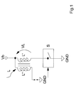
- reference number 1 indicates as a whole and diagrammatically a circuit provided in accordance with the present invention for detecting the presence of a spark produced by means of a spark coil L inserted in an electronic ignition device of an internal combustion motor.
- the coil L comprises a primary circuit L' inserted between a power supply voltage generator Vb and a controlled switch S and a secondary circuit L".
- the circuit 1 also comprises a first input block I provided e.g. by means of a resistive divider (R1,R2) having an input terminal connected to the primary circuit L' of the coil L and an output terminal.
- R1,R2 resistive divider
- This circuit comprises also a comparator C with hysteresis having a first input terminal connected to the output terminal of the input block I.
- the comparator also comprises a second and a third input terminals kept respectively at a first U1 and a second U2 reference voltage.
- this first reference voltage U1 and second reference voltage U2 represent respectively the upper and lower thresholds of the comparator C.
- the second reference voltage U2 is obtained preferably by means of a resistive divider (R3,R4) connected to the supply voltage generator Vb.
- the comparator C also comprises a low-pass filter FB.
- the circuit 1 also comprises a second signalling block SEG having an input terminal connected to an output terminal of the comparator C and an output terminal which is an output terminal OUT in the drawing of the circuit 1.
- This second signalling block SEG comprises in turn a counter CON having a first input terminal connected to the output terminal of the comparator C and a second input terminal receiving a timing signal Ck.
- the counter CON has an output connected to an input of a digital comparator CD having a second input terminal connected to a memory element M in which is memorized a binary reference value B.
- the comparator C with hysteresis compares this voltage U with the upper threshold U1 and lower threshold U2.
- a voltage Vc which is at a high logic level when the voltage U exceeds the threshold value U1.
- the voltage Vc by means of the filter FB keeps this logic level high for the entire duration of the transient until the voltage U falls below the lower threshold value U2 as shown in FIG. 4.
- the duration of the voltage Vc is proportional to the duration of the overvoltage created on the primary circuit L' of the coil L when the controlled switch S opens.
Description
Claims (5)
- Method for detecting the presence of a spark produced by means of a spark coil (L) having a primary circuit (L') connected to a supply voltage generator (Vb) and a secondary circuit (L"), said spark coil (L) being inserted in an electronic ignition device of an internal combustion motor and said method being characterized in that it consists of the following phases:generating a first voltage signal (U) proportional to )a voltage (VL) present on the primary circuit of the spark coil (L),comparing said first voltage signal (U) with a first, upper, threshold value (U1) and in response producing a second voltage signal (Vc) at a first logic level when the first voltage signal (U) exceeds the first, upper, threshold value (U1),maintaining said second voltage signal (Vc) at the first logic level,comparing said first voltage signal (U) with a second, lower, threshold value (U2), proportional to the supply voltage (Vb), and in response producing the second voltage signal (Vc) at a second logic level when the first voltage signal (U) falls below the second, lower, threshold value (U2),detecting the time duration of the second voltage signal (Vc), andsignalling the presence of a spark on the secondary winding if said time duration exceeds a reference value (B).
- Method in accordance with claim 1 and characterized in ;that the phase of detecting the time duration of the second voltage signal (Vc) includes the phase of:generating a value (A) proportional to the time duration of the second voltage signal (Vc).
- Method in accordance with claim 2 and characterized in that the phase of signalling the presence of a spark includes the phase of:producing an output value (OUT) at a high logic level when the time duration of the second voltage signal (Vc) exceeds the reference value (B).
- Method in accordance with claim 1 and characterized in that the first, upper, threshold value (U1) is constant.
- Method in accordance with claim 1 and characterized in that the first logic level is high and the second logic level is low.
Priority Applications (3)
| Application Number | Priority Date | Filing Date | Title |
|---|---|---|---|
| DE69527702T DE69527702T2 (en) | 1995-04-28 | 1995-04-28 | Method and circuit for detecting an ignition spark in an internal combustion engine |
| EP95830169A EP0740072B1 (en) | 1995-04-28 | 1995-04-28 | Method and circuit for detecting the presence of a spark in internal combustion engine |
| US08/639,779 US5790039A (en) | 1995-04-28 | 1996-04-29 | Method for detecting the presence of a spark in an electronic ignition system used with an internal combustion engine |
Applications Claiming Priority (1)
| Application Number | Priority Date | Filing Date | Title |
|---|---|---|---|
| EP95830169A EP0740072B1 (en) | 1995-04-28 | 1995-04-28 | Method and circuit for detecting the presence of a spark in internal combustion engine |
Publications (2)
| Publication Number | Publication Date |
|---|---|
| EP0740072A1 EP0740072A1 (en) | 1996-10-30 |
| EP0740072B1 true EP0740072B1 (en) | 2002-08-07 |
Family
ID=8221908
Family Applications (1)
| Application Number | Title | Priority Date | Filing Date |
|---|---|---|---|
| EP95830169A Expired - Lifetime EP0740072B1 (en) | 1995-04-28 | 1995-04-28 | Method and circuit for detecting the presence of a spark in internal combustion engine |
Country Status (3)
| Country | Link |
|---|---|
| US (1) | US5790039A (en) |
| EP (1) | EP0740072B1 (en) |
| DE (1) | DE69527702T2 (en) |
Cited By (1)
| Publication number | Priority date | Publication date | Assignee | Title |
|---|---|---|---|---|
| TWI463144B (en) * | 2012-08-17 | 2014-12-01 | Prolific Technology Inc | Spark detection device capable of detecting characters of spark signal |
Families Citing this family (13)
| Publication number | Priority date | Publication date | Assignee | Title |
|---|---|---|---|---|
| JP3228159B2 (en) * | 1996-12-06 | 2001-11-12 | トヨタ自動車株式会社 | Engine spark plug inspection method |
| KR100564083B1 (en) * | 1997-08-12 | 2006-03-27 | 지멘스 악티엔게젤샤프트 | Measuring and diagnostic device for an ignition system of an internal combustion engine |
| US6278278B1 (en) | 1998-08-12 | 2001-08-21 | Siemens Aktiengesellschaft | Measuring and diagnostic device for an ignition system of an internal combustion engine |
| DE60015711T2 (en) | 2000-01-27 | 2005-11-24 | Stmicroelectronics S.R.L., Agrate Brianza | Electronic ignition unit with limitation of the voltage to a connection of the ignition coil primary winding |
| US6492818B1 (en) * | 2000-11-06 | 2002-12-10 | Cummins, Inc. | Apparatus and method for determining component fault conditions as a function of primary coil voltage in a capacitive discharge ignition system |
| DE60226978D1 (en) * | 2001-06-27 | 2008-07-17 | Sony Corp | INTEGRATED SWITCHING DEVICE, INFORMATION PROCESSING DEVICE, INFORMATION RECORDING MEMORY MANAGEMENT METHOD, MOBILE DEVICE DEVICE, INTEGRATED SEMICONDUCTOR SWITCHING DEVICE AND COMMUNICATION METHOD WITH A PORTABLE TERMINAL |
| DE102006054016A1 (en) * | 2006-11-16 | 2008-05-21 | Bayerische Motoren Werke Ag | Electronic monitoring of the electrical system of a motor vehicle for voltage peaks or voltage dips |
| ITMI20130002A1 (en) | 2013-01-03 | 2014-07-04 | St Microelectronics Srl | CONTROL SYSTEM OF AN IGNITION CANDLE AND ELECTRONIC MOTOR IGNITION SYSTEM WITH SECONDARY OPEN PROTECTION |
| CN103324226A (en) * | 2013-06-28 | 2013-09-25 | 成都汉康信息产业有限公司 | Overvoltage protection type telemetering terminal |
| JP5901718B1 (en) * | 2014-09-24 | 2016-04-13 | 三菱電機株式会社 | Internal combustion engine control device |
| EP3260778B1 (en) | 2016-06-21 | 2021-07-21 | John Zink Company, L.L.C. | System and method for electrical spark detection |
| CN106655084A (en) * | 2016-10-25 | 2017-05-10 | 上海联影医疗科技有限公司 | High-voltage generator ignition protection device and method |
| SE542389C2 (en) * | 2018-09-04 | 2020-04-21 | Sem Ab | An ignition system and method controlling spark ignited combustion engines |
Citations (1)
| Publication number | Priority date | Publication date | Assignee | Title |
|---|---|---|---|---|
| EP0654604A1 (en) * | 1993-11-22 | 1995-05-24 | Magneti Marelli France | Coil ignition method and device with additional discharges for diagnostics |
Family Cites Families (11)
| Publication number | Priority date | Publication date | Assignee | Title |
|---|---|---|---|---|
| US4377785A (en) * | 1979-07-06 | 1983-03-22 | Nippon Soken, Inc. | Device for diagnosing ignition system for use in internal combustion engine |
| IT1119341B (en) * | 1979-08-02 | 1986-03-10 | Cselt Centro Studi Lab Telecom | IMPULSIVE VOLTAGE ANALYZER |
| US4918389A (en) * | 1988-06-03 | 1990-04-17 | Robert Bosch Gmbh | Detecting misfiring in spark ignition engines |
| DE3907616A1 (en) * | 1989-03-09 | 1990-09-20 | Bosch Gmbh Robert | CIRCUIT ARRANGEMENT FOR MEASURING THE PRIMARY VOLTAGE OF A IGNITION COIL |
| US4913123A (en) * | 1989-03-23 | 1990-04-03 | Ford Motor Company | Ignition timing system with feedback correction |
| DE4009451C2 (en) * | 1989-03-27 | 1995-02-16 | Mitsubishi Electric Corp | Ignition device for an internal combustion engine |
| DE4020986C2 (en) * | 1990-07-02 | 1998-09-03 | Telefunken Microelectron | Electronic ignition system for an internal combustion engine |
| FR2676506B1 (en) * | 1991-05-15 | 1993-09-03 | Siemens Automotive Sa | METHOD AND DEVICE FOR DETECTING IGNITION RATES IN AN INTERNAL COMBUSTION ENGINE CYLINDER AND THEIR APPLICATION. |
| US5283527A (en) * | 1991-06-28 | 1994-02-01 | Ford Motor Company | Methods and apparatus for detecting short circuited secondary coil winding via monitoring primary coil winding |
| US5446385A (en) * | 1992-10-02 | 1995-08-29 | Robert Bosch Gmbh | Ignition system for internal combustion engines |
| US5534781A (en) * | 1994-08-15 | 1996-07-09 | Chrysler Corporation | Combustion detection via ionization current sensing for a "coil-on-plug" ignition system |
-
1995
- 1995-04-28 DE DE69527702T patent/DE69527702T2/en not_active Expired - Fee Related
- 1995-04-28 EP EP95830169A patent/EP0740072B1/en not_active Expired - Lifetime
-
1996
- 1996-04-29 US US08/639,779 patent/US5790039A/en not_active Expired - Lifetime
Patent Citations (1)
| Publication number | Priority date | Publication date | Assignee | Title |
|---|---|---|---|---|
| EP0654604A1 (en) * | 1993-11-22 | 1995-05-24 | Magneti Marelli France | Coil ignition method and device with additional discharges for diagnostics |
Cited By (1)
| Publication number | Priority date | Publication date | Assignee | Title |
|---|---|---|---|---|
| TWI463144B (en) * | 2012-08-17 | 2014-12-01 | Prolific Technology Inc | Spark detection device capable of detecting characters of spark signal |
Also Published As
| Publication number | Publication date |
|---|---|
| EP0740072A1 (en) | 1996-10-30 |
| DE69527702D1 (en) | 2002-09-12 |
| DE69527702T2 (en) | 2002-12-05 |
| US5790039A (en) | 1998-08-04 |
Similar Documents
| Publication | Publication Date | Title |
|---|---|---|
| EP0740072B1 (en) | Method and circuit for detecting the presence of a spark in internal combustion engine | |
| JPH088748B2 (en) | Full charge detection circuit | |
| US7525783B2 (en) | Monitoring method for an actuator and corresponding driver circuit | |
| KR960020286A (en) | Ring trip judgment circuit | |
| JP2002089426A (en) | Misfiring detector for internal combustion engine | |
| US4478200A (en) | Electronic ignition system for internal combustion engine capable of supplying electric power to auxiliary unit | |
| US6367318B1 (en) | Multicharge ignition system having combustion feedback for termination | |
| KR100297673B1 (en) | Ignition Control System | |
| EP0183223B1 (en) | Electronic ignition device for internal combustion engines | |
| JPH05223049A (en) | Ignition device for internal combustion engine | |
| EP0030816B1 (en) | A.c. electrical supply signalling arrangements | |
| KR930005158B1 (en) | Knock suppresing device | |
| US4082075A (en) | Input quarter cycle timing circuit | |
| GB2193822A (en) | Voltage regulation system for automotive charging generator | |
| US4204508A (en) | Ignition system for internal combustion engine | |
| US6948484B2 (en) | Capacitor discharge ignition device | |
| GB2180356A (en) | Ignition testing | |
| US4528972A (en) | Emergency ignition device for thermal engines with controlled ignition | |
| US4893085A (en) | Ignition monitoring circuit for an ignition system of an internal combustion engine including an erroneous pulse eliminating circuit means | |
| JPH10176643A (en) | Condenser charge/discharge ignition system | |
| JP3582961B2 (en) | Preignition detection device for internal combustion engine | |
| JP3283605B2 (en) | Ion current detector | |
| WO1997032218A2 (en) | Circuit for detecting a level or a level variation of an input direct voltage | |
| KR100700851B1 (en) | Ignition failure sensor for vehicles | |
| JPS62293941A (en) | Battery charging circuit |
Legal Events
| Date | Code | Title | Description |
|---|---|---|---|
| PUAI | Public reference made under article 153(3) epc to a published international application that has entered the european phase |
Free format text: ORIGINAL CODE: 0009012 |
|
| AK | Designated contracting states |
Kind code of ref document: A1 Designated state(s): DE FR GB IT |
|
| 17P | Request for examination filed |
Effective date: 19970421 |
|
| 17Q | First examination report despatched |
Effective date: 19970926 |
|
| RAP3 | Party data changed (applicant data changed or rights of an application transferred) |
Owner name: STMICROELECTRONICS S.R.L. |
|
| GRAG | Despatch of communication of intention to grant |
Free format text: ORIGINAL CODE: EPIDOS AGRA |
|
| RAP1 | Party data changed (applicant data changed or rights of an application transferred) |
Owner name: CHRYSLER CORPORATION Owner name: STMICROELECTRONICS S.R.L. |
|
| GRAG | Despatch of communication of intention to grant |
Free format text: ORIGINAL CODE: EPIDOS AGRA |
|
| GRAG | Despatch of communication of intention to grant |
Free format text: ORIGINAL CODE: EPIDOS AGRA |
|
| GRAH | Despatch of communication of intention to grant a patent |
Free format text: ORIGINAL CODE: EPIDOS IGRA |
|
| GRAH | Despatch of communication of intention to grant a patent |
Free format text: ORIGINAL CODE: EPIDOS IGRA |
|
| GRAA | (expected) grant |
Free format text: ORIGINAL CODE: 0009210 |
|
| RAP1 | Party data changed (applicant data changed or rights of an application transferred) |
Owner name: DAIMLERCHRYSLER CORPORATION Owner name: STMICROELECTRONICS S.R.L. |
|
| AK | Designated contracting states |
Kind code of ref document: B1 Designated state(s): DE FR GB IT |
|
| REG | Reference to a national code |
Ref country code: GB Ref legal event code: FG4D |
|
| REF | Corresponds to: |
Ref document number: 69527702 Country of ref document: DE Date of ref document: 20020912 |
|
| ET | Fr: translation filed | ||
| PLBE | No opposition filed within time limit |
Free format text: ORIGINAL CODE: 0009261 |
|
| STAA | Information on the status of an ep patent application or granted ep patent |
Free format text: STATUS: NO OPPOSITION FILED WITHIN TIME LIMIT |
|
| 26N | No opposition filed |
Effective date: 20030508 |
|
| PGFP | Annual fee paid to national office [announced via postgrant information from national office to epo] |
Ref country code: DE Payment date: 20040329 Year of fee payment: 10 |
|
| PG25 | Lapsed in a contracting state [announced via postgrant information from national office to epo] |
Ref country code: IT Free format text: LAPSE BECAUSE OF NON-PAYMENT OF DUE FEES;WARNING: LAPSES OF ITALIAN PATENTS WITH EFFECTIVE DATE BEFORE 2007 MAY HAVE OCCURRED AT ANY TIME BEFORE 2007. THE CORRECT EFFECTIVE DATE MAY BE DIFFERENT FROM THE ONE RECORDED. Effective date: 20050428 |
|
| PG25 | Lapsed in a contracting state [announced via postgrant information from national office to epo] |
Ref country code: DE Free format text: LAPSE BECAUSE OF NON-PAYMENT OF DUE FEES Effective date: 20051101 |
|
| PGFP | Annual fee paid to national office [announced via postgrant information from national office to epo] |
Ref country code: GB Payment date: 20060327 Year of fee payment: 12 |
|
| GBPC | Gb: european patent ceased through non-payment of renewal fee |
Effective date: 20070428 |
|
| PG25 | Lapsed in a contracting state [announced via postgrant information from national office to epo] |
Ref country code: GB Free format text: LAPSE BECAUSE OF NON-PAYMENT OF DUE FEES Effective date: 20070428 |
|
| PGFP | Annual fee paid to national office [announced via postgrant information from national office to epo] |
Ref country code: FR Payment date: 20070426 Year of fee payment: 13 |
|
| REG | Reference to a national code |
Ref country code: FR Ref legal event code: ST Effective date: 20081231 |
|
| REG | Reference to a national code |
Ref country code: FR Ref legal event code: CD |
|
| PG25 | Lapsed in a contracting state [announced via postgrant information from national office to epo] |
Ref country code: FR Free format text: LAPSE BECAUSE OF NON-PAYMENT OF DUE FEES Effective date: 20080430 |