EP3260778B1 - System and method for electrical spark detection - Google Patents
System and method for electrical spark detection Download PDFInfo
- Publication number
- EP3260778B1 EP3260778B1 EP17176990.4A EP17176990A EP3260778B1 EP 3260778 B1 EP3260778 B1 EP 3260778B1 EP 17176990 A EP17176990 A EP 17176990A EP 3260778 B1 EP3260778 B1 EP 3260778B1
- Authority
- EP
- European Patent Office
- Prior art keywords
- spark
- sound wave
- electrical
- igniter
- detector
- Prior art date
- Legal status (The legal status is an assumption and is not a legal conclusion. Google has not performed a legal analysis and makes no representation as to the accuracy of the status listed.)
- Active
Links
- 238000000034 method Methods 0.000 title claims description 58
- 238000001514 detection method Methods 0.000 title description 30
- 238000004891 communication Methods 0.000 claims description 10
- 230000002123 temporal effect Effects 0.000 claims description 8
- 230000001902 propagating effect Effects 0.000 claims description 6
- 238000012423 maintenance Methods 0.000 claims description 5
- 230000008878 coupling Effects 0.000 claims description 3
- 238000010168 coupling process Methods 0.000 claims description 3
- 238000005859 coupling reaction Methods 0.000 claims description 3
- 239000000446 fuel Substances 0.000 description 22
- 238000010586 diagram Methods 0.000 description 13
- 229910000831 Steel Inorganic materials 0.000 description 4
- 239000000463 material Substances 0.000 description 4
- 239000010959 steel Substances 0.000 description 4
- 238000012544 monitoring process Methods 0.000 description 3
- 239000000956 alloy Substances 0.000 description 2
- 230000008859 change Effects 0.000 description 2
- 238000011017 operating method Methods 0.000 description 2
- 230000008054 signal transmission Effects 0.000 description 2
- 230000004913 activation Effects 0.000 description 1
- 230000001934 delay Effects 0.000 description 1
- 230000005284 excitation Effects 0.000 description 1
- 239000002360 explosive Substances 0.000 description 1
- 238000010438 heat treatment Methods 0.000 description 1
- 239000010763 heavy fuel oil Substances 0.000 description 1
- 230000010355 oscillation Effects 0.000 description 1
- 238000012545 processing Methods 0.000 description 1
- 230000004044 response Effects 0.000 description 1
Images

Classifications
-
- G—PHYSICS
- G01—MEASURING; TESTING
- G01R—MEASURING ELECTRIC VARIABLES; MEASURING MAGNETIC VARIABLES
- G01R31/00—Arrangements for testing electric properties; Arrangements for locating electric faults; Arrangements for electrical testing characterised by what is being tested not provided for elsewhere
- G01R31/28—Testing of electronic circuits, e.g. by signal tracer
- G01R31/282—Testing of electronic circuits specially adapted for particular applications not provided for elsewhere
- G01R31/2829—Testing of circuits in sensor or actuator systems
-
- H—ELECTRICITY
- H01—ELECTRIC ELEMENTS
- H01T—SPARK GAPS; OVERVOLTAGE ARRESTERS USING SPARK GAPS; SPARKING PLUGS; CORONA DEVICES; GENERATING IONS TO BE INTRODUCED INTO NON-ENCLOSED GASES
- H01T13/00—Sparking plugs
- H01T13/58—Testing
- H01T13/60—Testing of electrical properties
-
- F—MECHANICAL ENGINEERING; LIGHTING; HEATING; WEAPONS; BLASTING
- F23—COMBUSTION APPARATUS; COMBUSTION PROCESSES
- F23Q—IGNITION; EXTINGUISHING-DEVICES
- F23Q3/00—Igniters using electrically-produced sparks
- F23Q3/006—Details
-
- F—MECHANICAL ENGINEERING; LIGHTING; HEATING; WEAPONS; BLASTING
- F23—COMBUSTION APPARATUS; COMBUSTION PROCESSES
- F23Q—IGNITION; EXTINGUISHING-DEVICES
- F23Q23/00—Testing of ignition installations
- F23Q23/02—Testing of ignition timing
-
- F—MECHANICAL ENGINEERING; LIGHTING; HEATING; WEAPONS; BLASTING
- F23—COMBUSTION APPARATUS; COMBUSTION PROCESSES
- F23Q—IGNITION; EXTINGUISHING-DEVICES
- F23Q23/00—Testing of ignition installations
- F23Q23/08—Testing of components
- F23Q23/10—Testing of components electrically
-
- G—PHYSICS
- G01—MEASURING; TESTING
- G01R—MEASURING ELECTRIC VARIABLES; MEASURING MAGNETIC VARIABLES
- G01R1/00—Details of instruments or arrangements of the types included in groups G01R5/00 - G01R13/00 and G01R31/00
- G01R1/44—Modifications of instruments for temperature compensation
-
- G—PHYSICS
- G01—MEASURING; TESTING
- G01R—MEASURING ELECTRIC VARIABLES; MEASURING MAGNETIC VARIABLES
- G01R35/00—Testing or calibrating of apparatus covered by the other groups of this subclass
- G01R35/005—Calibrating; Standards or reference devices, e.g. voltage or resistance standards, "golden" references
-
- H—ELECTRICITY
- H01—ELECTRIC ELEMENTS
- H01T—SPARK GAPS; OVERVOLTAGE ARRESTERS USING SPARK GAPS; SPARKING PLUGS; CORONA DEVICES; GENERATING IONS TO BE INTRODUCED INTO NON-ENCLOSED GASES
- H01T13/00—Sparking plugs
- H01T13/58—Testing
-
- F—MECHANICAL ENGINEERING; LIGHTING; HEATING; WEAPONS; BLASTING
- F23—COMBUSTION APPARATUS; COMBUSTION PROCESSES
- F23N—REGULATING OR CONTROLLING COMBUSTION
- F23N2227/00—Ignition or checking
- F23N2227/36—Spark ignition, e.g. by means of a high voltage
-
- F—MECHANICAL ENGINEERING; LIGHTING; HEATING; WEAPONS; BLASTING
- F23—COMBUSTION APPARATUS; COMBUSTION PROCESSES
- F23N—REGULATING OR CONTROLLING COMBUSTION
- F23N2231/00—Fail safe
- F23N2231/12—Fail safe for ignition failures
Definitions
- High energy spark, or electrical arc, ignition systems deliver electric arcs to a gapped anode/cathode electrode set on a spark igniter for the purpose of igniting fuel in a burner.
- Loss of spark at the igniter electrode gap results in a no-start condition in a burner, and where raw fuel is introduced during such a no-start condition, a dangerous and potentially explosive situation can arise in the burner.
- detection of sparks on the spark igniter gapped electrode before introduction of fuel is desirable in an effort to reduce the dangers associated with raw fuel introduction into a burner.
- An electrical spark system belonging to the prior art is known, for example, from US 2015/322863 A1 .
- a spark detector analyzes a spark sound wave generated by an electrical spark, produced from electrical spark generator located on an igniter rod, to determine presence of the spark.
- the spark detector includes an acoustic sensor that is in communication with the igniter rod to determine the time of flight for the spark sound wave to travel through the igniter rod to the acoustic sensor.
- the spark detector may output a signal indicating a spark characteristic, such as successful or unsuccessful spark. If a spark is not detected, the spark detector may output a signal indicating at least one of (i) the spark was not detected, (ii) to replace the electrical spark generator immediately, or (iii) replace the electrical spark generator soon such as at the next scheduled maintenance.
- the spark detector is calibrated based on current temperature of the igniter rod based upon time of flight of a pulse sound wave, generated by a pulse-echo generator, reflecting off of an end of the igniter rod.
- an electrical spark system comprises an acoustic sensor adapted to sense a spark sound wave generated by an electrical spark, the spark sound wave propagating through an igniter rod in acoustic communication with the acoustic sensor.
- the electrical spark system further comprises a spark detector, in communication with the acoustic sensor, adapted to: (a) identify a first time period when the ignition signal is sent to the electrical spark generator, (b) identify a second time period defining when the acoustic sensor senses the sound wave, (c) identify a spark characteristic based on a temporal relationship between the first and second time periods as compared to a predetermined time range; and (d) generate an output defining the spark characteristic, wherein the spark detector further includes a pulse-echo generator for generating a pulse sound wave.
- a method for detecting an electrical spark comprises identifying, by a spark detector, an ignition control signal instructing an electrical spark generator to create a spark.
- the method further includes determining if a spark sound wave is detected by an acoustic sensor, the acoustic sensor being in communication with an igniter rod, the spark sound wave propagating through the igniter rod. Further, the method includes outputting, via the spark detector, a signal indicating a spark characteristic, the spark characteristic being based on a temporal relationship of said ignition control signal and said spark sound wave and a predetermined time range.
- the method detects a reflected pulse sound wave based on the pulse sound wave reflecting off of a second end of the igniter rod.
- the method may also calculate a spark detector adjustment based on a time of flight between the pulse sound wave and the reflected pulse sound wave. Further, the method may configure the electrical spark detector based on the spark detector adjustment.
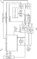
- FIG. 1 depicts an exemplary burner system 100 including a spark detector 102 for detecting an electrical spark 104 generated by an electrical spark generator 105 located on an igniter 106, in embodiments.
- a spark detector 102 for detecting an electrical spark 104 generated by an electrical spark generator 105 located on an igniter 106, in embodiments.
- an operator interfaces with operator interface 108 to control, via inputs 112 and outputs 114, burner management system 110.
- Burner management system 110 controls an exciter 116 by generating an excitation signal 118.
- Spark detector 102 may be integral to exciter 116, as shown in FIG. 1 , or may be a separate component from exciter 116 in other embodiments, as discussed further below.
- Exciter 116 generates a control signal 120, which is detected by spark detector 102. (In embodiments, spark detector 102 can alternatively generate the control signal 120.)
- Control signal 120 causes electrical spark generator 105 on igniter 106 to generate spark 104. Spark detector 102 then receives igniter feedback signal 122 to determine whether spark 104 occurred as intended.
- the spark detector 102 may generate a spark characteristic signal 124.
- a spark characteristic (as can be conveyed by spark characteristic signal 124) indicates at least one of a successful spark, an unsuccessful spark, a location of a detected spark within an igniter rod, and a ratio of successful sparks to unsuccessful sparks.
- spark detector 102 may return spark characteristic signal 124 to operator interface 108 (or to burner management system 110 in embodiments) indicating to replace the electrical spark generator 105. Additional details of fault characteristic signal 124, and the algorithms for determining when to send such signal are discussed below.
- burner management system 110 may generate valve operation signals 126 to control operation of one or more of fuel valve 128 and air valve 130, thereby letting fuel 132 and air 134 enter into a burner 136 via fuel/air input 138.
- Air valve 130, and air 134 through fuel/air input 138 may not be needed in embodiments where burner 136 is naturally aspirated.
- spark 104 which may be the same spark 104 as discussed above, or a secondary spark that is generated after igniter feedback signal 122 is generated.
- the fuel 132 is ignited and turns into flame(s) 140 thereby heating whatever medium 142 is within burner 136.
- burner 136 may include a flame detector 144 for determining the presence of flame(s) 140. If flame(s) 140 is detected (or, in embodiments, if a flame is not detected), flame detector 144 may send a flame detection signal 146 to burner management system 110.
- Embodiments may include a fuel removal system 148 for rapidly removing fuel 132 from within burner 136.
- Fuel removal system 148 may be activated based on fuel removal signal 150 generated by burner management system 110.
- Fuel removal signal 150 may be generated when fuel 132 has been fed into burner 136 for a predetermined period of time (or a predetermined amount of fuel 132 has entered burner 136) and igniter 106 is not generating spark 104, as detected by igniter feedback signal 122. Additionally or alternatively, fuel removal signal 150 may be generated when flame detector 144 fails to detect flames 140, as indicated by flame detection signal 146.
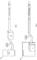
- FIG. 2 depicts an exemplary diagram 200 providing additional details of spark detector 102 and igniter 106 of FIG. 1 , as contemplated by embodiments.
- Igniter 106 couples to the housing of spark detector 102 at a first end of igniter rod 202.
- Igniter rod 202 may be directly coupled to the housing, or may be intermediately coupled to the housing via a harness (not shown).
- Igniter rod 202 may be rigid and made of steel, or other alloy material.
- igniter tip 204 At the opposite end of igniter rod 202 is igniter tip 204.
- Igniter tip 204 may include electrical spark generator 105 which, in embodiments, may include a cathode 206 and an anode 208 such that when control signal 120 is sent to the electrical spark generator 105, an arc is created between cathode 206 and anode 208.
- the electrical spark generator 105 on igniter tip 204 may include an insulating surface igniter (not shown). The electrical spark generator 105 may be located at other locations than igniter tip 204 without departing from the scope hereof. Referring back to FIG. 1 , electrical spark generator 105 on igniter tip 204 may be in communication with exciter 116 such that the electrical spark generator 105 is activated in response to control signal 120 to generate spark 104.
- an acoustic sensor 210 may be coupled to (or at least in acoustic communication with) igniter rod 202 to sense acoustic signals such as a spark sound wave 212 produced by spark 104 that travels through igniter rod 202.
- Acoustic sensor 210 may be a piezoelectric transducer which senses the acoustic signature of the spark sound wave 212.
- the spark 104 occurs at a specific point on the igniter rod 202 and the spark sound wave 212 propagates through the material of the igniter rod 202 and potentially any flexible harness/wire(s) leading to spark detector 102.
- the acoustic sensor 210 may be located on the housing of spark detector 102, such as near where igniter rod 202 attaches thereto, or alternatively acoustic sensor 210 may be placed directly on the igniter rod 202.
- this time delay is anywhere from the microsecond range to the millisecond range based on igniter rod 202 length and material, as well as other possible intermediary acoustic signal transmission mediums such as any flexible harness/wire(s) leading to spark detector 102.
- the time delay may be calculated based on the speed of sound in the material of igniter rod 202. For example, where igniter rod 202 is made from steel, spark sound wave 212 travels approximately at 5900 m/s. In embodiments, igniter rod 202 may be any length including from a foot or less to over 304,8 m (1000 feet).
- spark detector 102 further includes a pulse-echo generator 214 for generating pulse sound wave 216. Pulse sound wave 216 bounces off of the igniter tip 204 (or the end of the igniter rod 202) and reflects back to pulse-echo generator and acoustic sensor 210. In turn, acoustic sensor 210 may acquire the pulse sound wave 216 signature and such data may be used to calibrate, or recalibrate, spark detector 102.
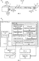
- FIG. 3 depicts a block diagram 300 of more detailed embodiments of spark detector 102.
- spark detector 102 includes processor 302 coupled with non-transitory memory 304 storing computer readable instructions that when executed by processor 302 perform the functionality of spark detector 102 as described herein.
- memory 304 stores spark detection logic 306, calibration settings 308, and calibration logic 310.
- Spark detection logic 306 enables functionality of spark detector 102 for detecting spark 104. When executed by processor 302, spark detection logic 306 generates control signal 120 to ignite electrical spark generator 105, such as by creating spark 104 between cathode 206 and anode 208. Spark detection logic 306 records the ignition time 312 defined by the time at which control signal 120 is generated. Ignition time 312 may be based upon clock 314 of processor 302. Alternatively ignition time 312 may be based on a transducer on the wire on which control signal 120 propagates such that, when control signal 120 passes through the wire, the transducer generates an output signal.
- Igniter feedback signal 122 is then stored in memory 304 as spark sound wave receipt time 316 indicating the time at which acoustic sensor 210 sensed spark sound wave 212.
- spark sound wave receipt time 316 is generated via the processor 302 monitoring the signal generated by acoustic sensor 210.
- the time on the clock 314 is stored as spark sound wave receipt time 316.
- This spark sound wave receipt time 316 may be adjusted based on processing and signal transmission delays required by processor 302. Spark detection logic 306 then in turn compares ignition time 312 with spark sound wave receipt time 316 to determine whether spark 104 occurred properly.
- Determining whether spark 104 occurred properly may be based on sensor to igniter distance 318 stored within memory 304, for example, within calibration settings 308. Knowledge of the sensor to igniter distance 318 enables spark detection logic 306 to have an understanding of how long it should take spark sound wave 212 to propagate through igniter rod 202 from electrical spark generator 105 and reach acoustic sensor 210. If the difference in time between ignition time 312 and spark sound wave receipt time 316 is within a specified detection range 320, which is based on sensor to igniter distance 318 and the speed of sound travel through the material that forms igniter rod 202, then a spark is successfully detected and processor 302 may output spark characteristic signal 124 indicating a successful spark.
- the processor 302 may output spark characteristic signal 124 indicating an unsuccessful spark to burner management system 110 or directly to operator interface 108.
- spark characteristic signal 124 may only detect 1) successful sparks, 2) unsuccessful (or lack of) sparks, or 3) successful and unsuccessful (or lack of) sparks, and output a spark characteristic signal 124 based thereon.
- spark detection logic 306 may also be capable of detecting whether and where a short circuit occurs along the leads that control electrical spark generator 105 (e.g. the leads leading to cathode 206 and anode 208).
- spark signatures 322 may be included that define various spark signatures of short circuit sounds. These spark signatures 322 may be preloaded into calibration settings 308. Spark signatures 322 may also include rules for identifying an exact location of the short circuit based upon time of the spark sound wave 212 reaching acoustic sensor 210.
- spark signatures 322 may define the distance along the igniter rod 202 that the short circuit occurred based upon comparing when the time control signal 120 is generated to the time acoustic sensor 210 senses the short circuit spark sound wave. In other words, embodiments may determine a location of the short circuit based upon timing calculations between generation of control signal 120 and receipt of spark sound wave 212.
- spark detector 102 may include calibration logic 310.
- Calibration logic 310 when executed by processor 302, controls pulse-echo generator 214 to generate pulse sound wave 216, as shown in FIG. 2 .
- Acoustic sensor 210 (or in alternate embodiments) pulse-echo generator 214) then detects the pulse sound wave 216 after it reflects off of igniter tip 204. Using sensor to igniter distance 318 (if the acoustic sensor 210 detects the reflected pulse sound wave 216), calibration logic can then generate igniter rod temperature adjustment 324.
- Igniter rod temperature adjustment 324 serves as an adjustment multiplier that may be used by spark detection logic 306 to readjust detection range 320 if the temperature of the igniter rod 202 affects the speed of the spark sound wave 212 as it travels through the igniter rod 202.
- spark detection logic 306 may also be utilized to identify the remaining lifespan of electrical spark generator 105.
- spark detection logic 306 may catalog successful sparks 326 and unsuccessful sparks 328.
- Successful sparks 326 occur when acoustic sensor 210 senses spark sound wave 212 within detection range 320.
- Unsuccessful sparks 328 occur when acoustic sensor 210 does not sense spark sound wave 212 within detection range 320.
- the ratio of successful sparks 326 to unsuccessful sparks 328 may then be compared against spark fault threshold 330.
- Spark fault threshold 330 defines the percentage of successful sparks 326 to unsuccessful sparks 328 that indicates whether the electrical spark generator 105 needs to be replaced.
- One such example ratio is 75% successful sparks.
- spark fault threshold 330 may identify the percentage of successful sparks 326 to unsuccessful sparks 328 that indicates whether the electrical spark generator 105 needs to be replaced soon.
- One such ratio is 80% successful sparks.
- the various ratios defined by spark fault threshold 330 may be higher or lower than 75% (for immediate replacement indication) or 80% (for replacement soon indication), without departing from the scope hereof.
- fuel 132 may not be allowed to enter the burner 136 unless the ratio of successful sparks 326 to unsuccessful sparks 328 is above a certain threshold.
- processor may output spark characteristic signal 124 to burner management system 110 (or directly to operator interface 108) indicating that the electrical spark generator 105 needs to be replaced immediately. Thereafter, the operator (or burner management system 110) may shut down burner 136 allowing for the immediately replacement of electrical spark generator 105.
- processor 302 may output spark characteristic signal 124 to burner management system 110 (or directly to operator interface 108) indicating that the electrical spark generator 105 needs to be replaced soon. Thereafter, the operator may replace the electrical spark generator 105 at the next planned maintenance.
- calibration settings 308 may additionally include filter 332 that operates to filter the signals received from acoustic sensor 210.
- filter 332 may be utilized to advantageously filter signals when there are a multitude of signals propagating through igniter rod 202. For example, where a short circuit occurs within, but distant from the igniter tip 204 of igniter rod 202, the sound wave created thereby will travel in both directions from the spark (i.e. towards both ends of the igniter rod 202).
- Filter 332 may thus be used to filter out these reflected short circuit sound waves based on timing of the received signal.
- FIG. 4 depicts a block diagram 400 of embodiments of the physical relationship between spark detector 102 and exciter 116.
- Spark detector 102 may be a separate device from exciter 116 and coupled thereto via flexible harness 402, for example.
- FIG. 5 depicts a block diagram 500 of the physical relationship between spark detector 102 and exciter 116, in other embodiments.
- spark detector 102 may be integral with exciter 116.
- igniter rod 202 may be coupled with spark detector via a flexible harness 502, which may be similar to flexible harness 402. It should be appreciated that other physical relationships between exciter 116 and spark detector 102 may be implemented without departing from the scope hereof.
- spark detector 102 may be integral to exciter 116, and igniter rod 202 may couple directly to spark detector 102 without flexible harness 502.
- FIG. 6 depicts a block diagram 600 showing embodiments of spark detector 102 coupled with igniter rod 202 having a plurality of acoustic sensors located thereon.
- FIG. 7 depicts an exemplary signal diagram 700 showing the spark sound wave signals sensed by each of the plurality of acoustic sensors of FIG. 6.
- FIGs. 6 and 7 are best viewed together with the following discussion.
- a first sensor 602 is located a distance D1 from igniter tip 204.
- a second sensor 604 is located a distance D2 from igniter tip 204.
- a third sensor 606 is located a third distance D3 from igniter tip 204.
- a transducer 608 is located at the opposite end of igniter rod 202 from igniter tip 204. Transducer 608 operates to detect a signal traveling to the electrical spark generator 105 (e.g. cathode and anode or insulating surface igniter) located on igniter tip 204. It should be appreciated that transducer 608 may not be required where the igniter control signal is detectable based on the processor that sends the signal.
- first acoustic sensor 602 produces first signal 702.
- Second acoustic sensor 604 produces second signal 704.
- Third acoustic sensor 606 produces third signal 706.
- transducer 608 produces transducer signal 708.
- Transducer signal 708 is representative of control signal 120 of FIG. 1 .
- Each of first, second, and third signals 702, 704, and 706, respectively, are representative of igniter feedback signal 122 of FIG. 1 .
- Valley 710 of transducer signal 708 indicates when control signal is sent to the electrical spark generator 105 to produce spark 104. It should be appreciated that valley 710 may be reversed, or in other words become a peak, based on the configuration of the transducer 608 without departing from the scope hereof.
- Peak 712 of first signal 702 indicates when the spark sound wave (e.g. spark sound wave 212), traveling through the igniter rod 202, is sensed by first acoustic sensor 602.
- Peak 714 of second signal 704 indicates when the spark sound wave (e.g. spark sound wave 212), traveling through the igniter rod 202, is sensed by second acoustic sensor 604.
- Peak 716 of third signal 706 indicates when the spark sound wave (e.g. spark sound wave 212), traveling through the igniter rod 202, is sensed by third acoustic sensor 606.
- filters 332 (of FIG. 3 ) are applied by spark detection logic 306, the filter may filter out additional information from signals 702-706 that occurs after each of valley 710 and peaks 712-716, respectively.
- the additional oscillation 718 may be filtered out by filter 332.
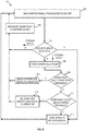
- FIG. 8 depicts embodiments for an exemplary method 800 for detecting a spark produced by an igniter.
- Method 800 may be implemented, for example, using spark detector 102 in communication with acoustic sensor 210 which is coupled with igniter rod 202, as shown in FIG. 2 .
- step 802 method 800, sends an ignition signal from the exciter to the igniter.
- control signal 120 is sent to electrical spark generator 105 to create spark 104.
- Step 804 is a decision in which method 800 determines if an acoustic signal travelling through the igniter rod 202 is detected. If a spark is detected, method 800 proceeds to step 818, if included, or repeats step 802. If a spark is not detected, method 800 proceeds with either path 1 to step 806, or path 2 to step 808. Path 1 may be taken where the system operating method 800 does not monitor electrical spark generator lifespan. Path 2 may be taken where the system operating method 800 is also used to monitor electrical spark generator lifespan. In one example of operation of step 804, acoustic sensor 210 is utilized to sense spark sound wave 212 and generates igniter feedback signal 122.
- spark detection logic 306 identifies a spark. If igniter feedback signal 122 indicates that spark sound wave 212 was not detected within detection range 320, then spark detection logic 306 identifies an unsuccessful (i.e., lack of) spark. If an unsuccessful spark is identified at decision 804, processor 302 may output spark characteristic signal 124 to burner management system 110, or directly to operator interface 108, indicating an unsuccessful spark.
- step 806 embodiments of method 800 contemplate implementing spark fault countermeasure(s).
- spark fault counter measure includes activation of fuel removal system 148 to remove any residual fuel 132 within burner 136. Additionally, or alternatively, the spark fault counter measure may include one or more of replace electrical spark generator 105 igniter 106, exciter 116, or spark detector 102, and perform system diagnostics. After step 806, method 800 repeats step 802.
- method 800 updates a spark fault count.
- spark detection logic 306 increases the unsuccessful spark 328 count.
- Method 800 then proceeds with step 810.
- method 800 can alternatively proceed directly to step 814, 806 or repeat step 802.
- Step 810 is a decision.
- method 800 determines if the spark fault count is above a stop threshold. If the spark fault count is determined to be above a stop threshold, method 800 proceeds to step 812. If the spark fault count is determined to be below the stop threshold, method 800 proceeds to step 814, or, in embodiments, directly to step 818 or repeats step 802.
- spark detection logic 306 analyzes the ratio of unsuccessful sparks 328 to successful sparks 326 to determine if the ratio is above spark fault threshold 330, which indicates when an electrical spark generator has reached the end of its lifespan.
- step 812 method 800 outputs a stop/replace signal to the operator.
- spark characteristic signal 124 is sent to burner management system 110, or directly to operator interface 108, indicating that electrical spark generator 105 needs to be immediately replaced.
- Step 814 is a decision.
- method 800 determines of the spark fault count is above a warning threshold. If the spark fault count is determined to be above a warning threshold, method 800 proceeds to step 816. If the spark fault count is determined to be above the warning threshold, method proceeds to step 818, or, in embodiments directly repeats step 802.
- spark detection logic 306 analyzes the ratio between unsuccessful sparks 328 and successful sparks 326 to determine if the ratio is above spark fault threshold 330, which indicates when an electrical spark generator is about to reach the end of its lifespan.
- step 816 method 800 outputs a replace igniter soon signal to the operator.
- spark characteristic signal 124 is sent to burner management system 110, or directly to operator interface 108, indicating that electrical spark generator 105 needs to be replaced at the next burner maintenance performance.
- step 818 method 800 sends a spark OK indication signal to the operator (or the burner management system in embodiments).
- spark characteristic signal 124 of FIG. 1 , is sent to burner management system 110, or directly to operator interface 108, indicating a successful spark.
- Method 800 repeats for each spark control signal sent to the electrical spark generator 105. However, in certain embodiments, method 800 may only be performed for a portion of the spark control signals. For example, where the electrical spark generator 105 operates at 0.1 Hz, or 1 spark per 10 seconds, only one spark may be subjected to method 800 each second. Alternatively, 2 or more sparks may be subjected to method 800 each second.
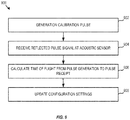
- FIG. 9 depicts embodiments of an exemplary method 900 for calibrating a spark detector.
- Method 900 is for example implemented using pulse-echo generator 214 and spark detector 102, of FIG. 2 .
- step 902 method 900 generates a calibration pulse for determining one or more calibration settings of the spark detector.
- pulse-echo generator 214 generates pulse sound wave 216 within igniter rod 202.
- step 904 receives a reflected pulse signal at an acoustic sensor.
- the pulse sound wave 216 reflects off of the opposite end of igniter rod 202, for example off of igniter tip 204, and is detected by an acoustic sensor, which may be acoustic sensor 210 or a separate acoustic sensor associated with the pulse-echo generator 214.
- step 906 calculates the time of flight from pulse generation during step 902 to pulse receipt during step 904.
- calibration logic 310 determines the temporal duration between when pulse-echo generator 214 generated pulse sound wave 216 and when the acoustic sensor (either acoustic sensor 210 or an acoustic sensor associated with pulse-echo generator 214) sensed the pulse sound wave 216 reflected off of the end of igniter rod 202.
- step 908 updates the configuration settings of the spark detector.
- calibration logic 310 updates igniter rod temperature adjustment 324 within calibration settings 308.
- Method 900 may be implemented at any time during method 800 to configure spark generator according to the actual characteristics of igniter rod. This allows the igniter rod to increase in temperature during operation of the burner and still provide for an accurate detection of whether a spark occurs.
- the signal detected by the acoustic sensor represents the spark sound wave as opposed to the spark sound wave combined with numerous other ambient sound waves.
- the above described system and method embodiments provide significant advantages.
- the system and methods are capable of monitoring the spark sound wave as it travels through the igniter rod itself.
- the spark detection to a fuel removal system, the potential for improper or dangerous fuel ignition caused when faulty sparks occur is significantly reduced.
Description
- High energy spark, or electrical arc, ignition systems deliver electric arcs to a gapped anode/cathode electrode set on a spark igniter for the purpose of igniting fuel in a burner. Loss of spark at the igniter electrode gap results in a no-start condition in a burner, and where raw fuel is introduced during such a no-start condition, a dangerous and potentially explosive situation can arise in the burner. Thus, detection of sparks on the spark igniter gapped electrode before introduction of fuel is desirable in an effort to reduce the dangers associated with raw fuel introduction into a burner. An electrical spark system belonging to the prior art is known, for example, from
US 2015/322863 A1 . - A spark detector analyzes a spark sound wave generated by an electrical spark, produced from electrical spark generator located on an igniter rod, to determine presence of the spark. The spark detector includes an acoustic sensor that is in communication with the igniter rod to determine the time of flight for the spark sound wave to travel through the igniter rod to the acoustic sensor. The spark detector may output a signal indicating a spark characteristic, such as successful or unsuccessful spark. If a spark is not detected, the spark detector may output a signal indicating at least one of (i) the spark was not detected, (ii) to replace the electrical spark generator immediately, or (iii) replace the electrical spark generator soon such as at the next scheduled maintenance. Furthermore, the spark detector is calibrated based on current temperature of the igniter rod based upon time of flight of a pulse sound wave, generated by a pulse-echo generator, reflecting off of an end of the igniter rod.
- According to the invention, an electrical spark system comprises an acoustic sensor adapted to sense a spark sound wave generated by an electrical spark, the spark sound wave propagating through an igniter rod in acoustic communication with the acoustic sensor. The electrical spark system further comprises a spark detector, in communication with the acoustic sensor, adapted to: (a) identify a first time period when the ignition signal is sent to the electrical spark generator, (b) identify a second time period defining when the acoustic sensor senses the sound wave, (c) identify a spark characteristic based on a temporal relationship between the first and second time periods as compared to a predetermined time range; and (d) generate an output defining the spark characteristic, wherein the spark detector further includes a pulse-echo generator for generating a pulse sound wave.
- In another aspect of the invention, a method for detecting an electrical spark comprises identifying, by a spark detector, an ignition control signal instructing an electrical spark generator to create a spark. The method further includes determining if a spark sound wave is detected by an acoustic sensor, the acoustic sensor being in communication with an igniter rod, the spark sound wave propagating through the igniter rod. Further, the method includes outputting, via the spark detector, a signal indicating a spark characteristic, the spark characteristic being based on a temporal relationship of said ignition control signal and said spark sound wave and a predetermined time range.
- In yet another aspect of the invention, the method for detecting an electrical spark also comprises a method for calibrating an electrical spark detector comprises generating, via a pulse-echo generator located at a first end of an igniter rod, a pulse sound wave. The method detects a reflected pulse sound wave based on the pulse sound wave reflecting off of a second end of the igniter rod. The method may also calculate a spark detector adjustment based on a time of flight between the pulse sound wave and the reflected pulse sound wave. Further, the method may configure the electrical spark detector based on the spark detector adjustment.
-
-
FIG. 1 depicts an exemplary burner system including a spark detector for detecting an electrical spark generated by igniter, in embodiments. -
FIG. 2 depicts an exemplary diagram providing additional details of the spark detector and igniter ofFIG. 1 , in embodiments. -
FIG. 3 depicts a block diagram of the spark detector ofFIGs. 1-2 , in embodiments. -
FIG. 4 depicts a block diagram of the physical relationship between the spark detector and exciter ofFIGs. 1-3 , in embodiments. -
FIG. 5 depicts a block diagram of the physical relationship between the spark detector and exciter ofFIGs. 1-3 , in alternate and overlapping embodiments. -
FIG. 6 depicts a block diagram of the spark detector module ofFIGs. 1-3 coupled with igniter rod having a plurality of acoustic sensors located thereon, in embodiments. -
FIG. 7 depicts an exemplary signal diagram showing the spark sound wave signals sensed by each of the plurality of acoustic sensors ofFIG. 6 . -
FIG. 8 depicts an exemplary method for detecting a spark produced by an igniter, in embodiments. -
FIG. 9 depicts an exemplary method for calibrating a spark detector, in embodiments. -
FIG. 1 depicts anexemplary burner system 100 including aspark detector 102 for detecting anelectrical spark 104 generated by anelectrical spark generator 105 located on anigniter 106, in embodiments. In operation ofburner system 100, an operator interfaces withoperator interface 108 to control, viainputs 112 andoutputs 114,burner management system 110. -
Burner management system 110 controls anexciter 116 by generating anexcitation signal 118.Spark detector 102 may be integral to exciter 116, as shown inFIG. 1 , or may be a separate component from exciter 116 in other embodiments, as discussed further below. Exciter 116 generates acontrol signal 120, which is detected byspark detector 102. (In embodiments,spark detector 102 can alternatively generate thecontrol signal 120.)Control signal 120 causeselectrical spark generator 105 onigniter 106 to generatespark 104.Spark detector 102 then receivesigniter feedback signal 122 to determine whetherspark 104 occurred as intended. - Based on the temporal relationship between when the
control signal 120 is generated and when a spark sound wave is sensed, as indicated within theigniter feedback signal 122, thespark detector 102 may generate aspark characteristic signal 124. In embodiments, a spark characteristic (as can be conveyed by spark characteristic signal 124) indicates at least one of a successful spark, an unsuccessful spark, a location of a detected spark within an igniter rod, and a ratio of successful sparks to unsuccessful sparks. Ifigniter feedback signal 122 indicates one or more of (i) theelectrical spark generator 105 onigniter 106 did not producespark 104, (ii) theelectrical spark generator 105 onigniter 106 has reached the end of its lifecycle, and (iii) theelectrical spark generator 105 onigniter 106 is near the end of its lifecycle,spark detector 102 may returnspark characteristic signal 124 to operator interface 108 (or toburner management system 110 in embodiments) indicating to replace theelectrical spark generator 105. Additional details offault characteristic signal 124, and the algorithms for determining when to send such signal are discussed below. - If
igniter feedback 122 indicates thatspark 104 is generated byelectrical spark generator 105 onigniter 106, thenburner management system 110 may generatevalve operation signals 126 to control operation of one or more offuel valve 128 andair valve 130, thereby lettingfuel 132 andair 134 enter into aburner 136 via fuel/air input 138.Air valve 130, andair 134 through fuel/air input 138 may not be needed in embodiments whereburner 136 is naturally aspirated. - Once
fuel 132 andair 134 enter intoburner 136, they are ignited byspark 104, which may be thesame spark 104 as discussed above, or a secondary spark that is generated afterigniter feedback signal 122 is generated. In turn, thefuel 132 is ignited and turns into flame(s) 140 thereby heating whatevermedium 142 is withinburner 136. - In embodiments,
burner 136 may include aflame detector 144 for determining the presence of flame(s) 140. If flame(s) 140 is detected (or, in embodiments, if a flame is not detected),flame detector 144 may send aflame detection signal 146 toburner management system 110. - Embodiments may include a
fuel removal system 148 for rapidly removingfuel 132 from withinburner 136.Fuel removal system 148 may be activated based onfuel removal signal 150 generated byburner management system 110.Fuel removal signal 150 may be generated whenfuel 132 has been fed intoburner 136 for a predetermined period of time (or a predetermined amount offuel 132 has entered burner 136) andigniter 106 is not generatingspark 104, as detected byigniter feedback signal 122. Additionally or alternatively,fuel removal signal 150 may be generated whenflame detector 144 fails to detectflames 140, as indicated byflame detection signal 146. -
FIG. 2 depicts an exemplary diagram 200 providing additional details ofspark detector 102 andigniter 106 ofFIG. 1 , as contemplated by embodiments. Igniter 106 couples to the housing ofspark detector 102 at a first end ofigniter rod 202. Igniterrod 202 may be directly coupled to the housing, or may be intermediately coupled to the housing via a harness (not shown). Igniterrod 202 may be rigid and made of steel, or other alloy material. At the opposite end ofigniter rod 202 isigniter tip 204. Ignitertip 204 may includeelectrical spark generator 105 which, in embodiments, may include acathode 206 and ananode 208 such that whencontrol signal 120 is sent to theelectrical spark generator 105, an arc is created betweencathode 206 andanode 208. Alternatively, theelectrical spark generator 105 onigniter tip 204 may include an insulating surface igniter (not shown). Theelectrical spark generator 105 may be located at other locations thanigniter tip 204 without departing from the scope hereof. Referring back toFIG. 1 ,electrical spark generator 105 onigniter tip 204 may be in communication withexciter 116 such that theelectrical spark generator 105 is activated in response tocontrol signal 120 to generatespark 104. - Referring again to
FIG. 2 , anacoustic sensor 210 may be coupled to (or at least in acoustic communication with)igniter rod 202 to sense acoustic signals such as aspark sound wave 212 produced byspark 104 that travels throughigniter rod 202.Acoustic sensor 210 may be a piezoelectric transducer which senses the acoustic signature of thespark sound wave 212. Thespark 104 occurs at a specific point on theigniter rod 202 and thespark sound wave 212 propagates through the material of theigniter rod 202 and potentially any flexible harness/wire(s) leading tospark detector 102. Theacoustic sensor 210 may be located on the housing ofspark detector 102, such as near whereigniter rod 202 attaches thereto, or alternativelyacoustic sensor 210 may be placed directly on theigniter rod 202. - There is a delay in time between the
moment spark 104 occurs and thespark sound wave 212 propagates down theignition rod 202 reaching the sensor. In embodiments, this time delay is anywhere from the microsecond range to the millisecond range based onigniter rod 202 length and material, as well as other possible intermediary acoustic signal transmission mediums such as any flexible harness/wire(s) leading to sparkdetector 102. The time delay may be calculated based on the speed of sound in the material ofigniter rod 202. For example, whereigniter rod 202 is made from steel, sparksound wave 212 travels approximately at 5900 m/s. In embodiments,igniter rod 202 may be any length including from a foot or less to over 304,8 m (1000 feet). - In should be understood that, as the
igniter rod 202 is utilized in burner 136 (referring toFigure 1 ) or another system, the temperature ofigniter rod 202 may change. As the temperature ofigniter rod 202 changes, the speed at which sparksound wave 212 travels throughigniter rod 202 may also change. To account for this, the invention envisions thatspark detector 102 further includes a pulse-echo generator 214 for generatingpulse sound wave 216.Pulse sound wave 216 bounces off of the igniter tip 204 (or the end of the igniter rod 202) and reflects back to pulse-echo generator andacoustic sensor 210. In turn,acoustic sensor 210 may acquire thepulse sound wave 216 signature and such data may be used to calibrate, or recalibrate,spark detector 102. -
FIG. 3 depicts a block diagram 300 of more detailed embodiments ofspark detector 102. Referring toFIG 3 (in conjunction withFIGS 1 and2 ),spark detector 102 includesprocessor 302 coupled withnon-transitory memory 304 storing computer readable instructions that when executed byprocessor 302 perform the functionality ofspark detector 102 as described herein. In embodiments,memory 304 stores sparkdetection logic 306,calibration settings 308, andcalibration logic 310. -
Spark detection logic 306 enables functionality ofspark detector 102 for detectingspark 104. When executed byprocessor 302,spark detection logic 306 generatescontrol signal 120 to igniteelectrical spark generator 105, such as by creatingspark 104 betweencathode 206 andanode 208.Spark detection logic 306 records theignition time 312 defined by the time at which control signal 120 is generated.Ignition time 312 may be based uponclock 314 ofprocessor 302. Alternativelyignition time 312 may be based on a transducer on the wire on which control signal 120 propagates such that, when control signal 120 passes through the wire, the transducer generates an output signal. -
Igniter feedback signal 122 is then stored inmemory 304 as spark soundwave receipt time 316 indicating the time at whichacoustic sensor 210 sensedspark sound wave 212. In particular, spark soundwave receipt time 316 is generated via theprocessor 302 monitoring the signal generated byacoustic sensor 210. When said signal indicates thatspark sound wave 212 is detected, for example based on a specific pattern in the signal matching thespark sound wave 212, the time on theclock 314 is stored as spark soundwave receipt time 316. This spark soundwave receipt time 316 may be adjusted based on processing and signal transmission delays required byprocessor 302.Spark detection logic 306 then in turn comparesignition time 312 with spark soundwave receipt time 316 to determine whetherspark 104 occurred properly. Determining whetherspark 104 occurred properly may be based on sensor to igniter distance 318 stored withinmemory 304, for example, withincalibration settings 308. Knowledge of the sensor to igniter distance 318 enablesspark detection logic 306 to have an understanding of how long it should takespark sound wave 212 to propagate throughigniter rod 202 fromelectrical spark generator 105 and reachacoustic sensor 210. If the difference in time betweenignition time 312 and spark soundwave receipt time 316 is within a specifieddetection range 320, which is based on sensor to igniter distance 318 and the speed of sound travel through the material that formsigniter rod 202, then a spark is successfully detected andprocessor 302 may output sparkcharacteristic signal 124 indicating a successful spark. However, if the difference in time betweenignition time 312 and spark soundwave receipt time 316 is outside specifieddetection range 320, theprocessor 302 may output sparkcharacteristic signal 124 indicating an unsuccessful spark toburner management system 110 or directly tooperator interface 108. Thus, it should be appreciated that embodiments envisioned herein may only detect 1) successful sparks, 2) unsuccessful (or lack of) sparks, or 3) successful and unsuccessful (or lack of) sparks, and output a sparkcharacteristic signal 124 based thereon. - In embodiments, spark
detection logic 306 may also be capable of detecting whether and where a short circuit occurs along the leads that control electrical spark generator 105 (e.g. the leads leading tocathode 206 and anode 208). For example, sparksignatures 322 may be included that define various spark signatures of short circuit sounds. These sparksignatures 322 may be preloaded intocalibration settings 308.Spark signatures 322 may also include rules for identifying an exact location of the short circuit based upon time of thespark sound wave 212 reachingacoustic sensor 210. For example, if thespark sound wave 212 reachesacoustic sensor 210 outside ofdetection range 320, there is a strong probability that thatspark sound wave 212 was not generated by theelectrical spark generator 105, but instead was generated by a short circuit in theigniter rod 202. Therefore, sparksignatures 322 may define the distance along theigniter rod 202 that the short circuit occurred based upon comparing when thetime control signal 120 is generated to the timeacoustic sensor 210 senses the short circuit spark sound wave. In other words, embodiments may determine a location of the short circuit based upon timing calculations between generation ofcontrol signal 120 and receipt ofspark sound wave 212. - As discussed above, temperature of
igniter rod 202 may influence the speed at whichsound wave 212 travels throughigniter rod 202. Therefore, embodiments envision thatspark detector 102 may includecalibration logic 310.Calibration logic 310, when executed byprocessor 302, controls pulse-echo generator 214 to generatepulse sound wave 216, as shown inFIG. 2 .Acoustic sensor 210, (or in alternate embodiments) pulse-echo generator 214) then detects thepulse sound wave 216 after it reflects off ofigniter tip 204. Using sensor to igniter distance 318 (if theacoustic sensor 210 detects the reflected pulse sound wave 216), calibration logic can then generate igniter rod temperature adjustment 324. Igniter rod temperature adjustment 324 serves as an adjustment multiplier that may be used byspark detection logic 306 to readjustdetection range 320 if the temperature of theigniter rod 202 affects the speed of thespark sound wave 212 as it travels through theigniter rod 202. - In embodiments, spark
detection logic 306 may also be utilized to identify the remaining lifespan ofelectrical spark generator 105. For example, sparkdetection logic 306 may catalogsuccessful sparks 326 andunsuccessful sparks 328.Successful sparks 326 occur whenacoustic sensor 210 senses sparksound wave 212 withindetection range 320.Unsuccessful sparks 328 occur whenacoustic sensor 210 does not sensespark sound wave 212 withindetection range 320. The ratio ofsuccessful sparks 326 tounsuccessful sparks 328 may then be compared againstspark fault threshold 330.Spark fault threshold 330 defines the percentage ofsuccessful sparks 326 tounsuccessful sparks 328 that indicates whether theelectrical spark generator 105 needs to be replaced. One such example ratio is 75% successful sparks. Additionally, sparkfault threshold 330 may identify the percentage ofsuccessful sparks 326 tounsuccessful sparks 328 that indicates whether theelectrical spark generator 105 needs to be replaced soon. One such ratio is 80% successful sparks. The various ratios defined byspark fault threshold 330 may be higher or lower than 75% (for immediate replacement indication) or 80% (for replacement soon indication), without departing from the scope hereof. Further, in certain embodiments,fuel 132 may not be allowed to enter theburner 136 unless the ratio ofsuccessful sparks 326 tounsuccessful sparks 328 is above a certain threshold. - Various electrical spark generators operate at different frequencies, from 0.1 Hz to over 120 Hz. Therefore, by monitoring the successful sparks compared to unsuccessful sparks, the operator is able to predict when the
electrical spark generator 105 needs to be replaced. - Thus, if the percentage of
successful sparks 326 tounsuccessful sparks 328 indicates that the electrical spark generator needs to be replaced immediately, processor may output sparkcharacteristic signal 124 to burner management system 110 (or directly to operator interface 108) indicating that theelectrical spark generator 105 needs to be replaced immediately. Thereafter, the operator (or burner management system 110) may shut downburner 136 allowing for the immediately replacement ofelectrical spark generator 105. Alternatively, if the percentage ofsuccessful sparks 326 tounsuccessful sparks 328 indicates that theelectrical spark generator 105 needs to be replaced soon,processor 302 may output sparkcharacteristic signal 124 to burner management system 110 (or directly to operator interface 108) indicating that theelectrical spark generator 105 needs to be replaced soon. Thereafter, the operator may replace theelectrical spark generator 105 at the next planned maintenance. - In embodiments,
calibration settings 308 may additionally includefilter 332 that operates to filter the signals received fromacoustic sensor 210. Where theelectrical spark generator 105 operates at a high operating frequency, multiple sparks may be detected in close temporal proximity to one another. Moreover, signals propagating throughigniter rod 202 may bounce off of various surfaces of theigniter rod 202. Therefore, in embodiments,filter 332 may be utilized to advantageously filter signals when there are a multitude of signals propagating throughigniter rod 202. For example, where a short circuit occurs within, but distant from theigniter tip 204 ofigniter rod 202, the sound wave created thereby will travel in both directions from the spark (i.e. towards both ends of the igniter rod 202). The wave that propagates away from thesensor 210 will hit theigniter tip 204 of theigniter rod 202 and reflect back towards thesensor 210. However, said sound wave will arrive atsensor 210 later than its counterpart waveform which initially travels from the short circuit directly to thesensor 210. If consideration is not taken for this later-arriving wave, confusion may result regarding the precise status of the spark.Filter 332 may thus be used to filter out these reflected short circuit sound waves based on timing of the received signal. -
FIG. 4 depicts a block diagram 400 of embodiments of the physical relationship betweenspark detector 102 andexciter 116.Spark detector 102 may be a separate device fromexciter 116 and coupled thereto viaflexible harness 402, for example. -
FIG. 5 depicts a block diagram 500 of the physical relationship betweenspark detector 102 andexciter 116, in other embodiments. As shown,spark detector 102 may be integral withexciter 116. Moreover,igniter rod 202 may be coupled with spark detector via aflexible harness 502, which may be similar toflexible harness 402. It should be appreciated that other physical relationships betweenexciter 116 andspark detector 102 may be implemented without departing from the scope hereof. For example,spark detector 102 may be integral toexciter 116, andigniter rod 202 may couple directly to sparkdetector 102 withoutflexible harness 502. -
FIG. 6 depicts a block diagram 600 showing embodiments ofspark detector 102 coupled withigniter rod 202 having a plurality of acoustic sensors located thereon.FIG. 7 depicts an exemplary signal diagram 700 showing the spark sound wave signals sensed by each of the plurality of acoustic sensors ofFIG. 6. FIGs. 6 and 7 are best viewed together with the following discussion. - A
first sensor 602 is located a distance D1 fromigniter tip 204. Asecond sensor 604 is located a distance D2 fromigniter tip 204. And athird sensor 606 is located a third distance D3 fromigniter tip 204. Atransducer 608 is located at the opposite end ofigniter rod 202 fromigniter tip 204.Transducer 608 operates to detect a signal traveling to the electrical spark generator 105 (e.g. cathode and anode or insulating surface igniter) located onigniter tip 204. It should be appreciated thattransducer 608 may not be required where the igniter control signal is detectable based on the processor that sends the signal. - In signal diagram 700, first
acoustic sensor 602 producesfirst signal 702. Secondacoustic sensor 604 producessecond signal 704. Thirdacoustic sensor 606 producesthird signal 706. Andtransducer 608 producestransducer signal 708.Transducer signal 708 is representative ofcontrol signal 120 ofFIG. 1 . Each of first, second, andthird signals igniter feedback signal 122 ofFIG. 1 .Valley 710 oftransducer signal 708 indicates when control signal is sent to theelectrical spark generator 105 to producespark 104. It should be appreciated thatvalley 710 may be reversed, or in other words become a peak, based on the configuration of thetransducer 608 without departing from the scope hereof. Peak 712 offirst signal 702 indicates when the spark sound wave (e.g. spark sound wave 212), traveling through theigniter rod 202, is sensed by firstacoustic sensor 602. Peak 714 ofsecond signal 704 indicates when the spark sound wave (e.g. spark sound wave 212), traveling through theigniter rod 202, is sensed by secondacoustic sensor 604. Peak 716 ofthird signal 706 indicates when the spark sound wave (e.g. spark sound wave 212), traveling through theigniter rod 202, is sensed by thirdacoustic sensor 606. - If filters 332 (of
FIG. 3 ) are applied byspark detection logic 306, the filter may filter out additional information from signals 702-706 that occurs after each ofvalley 710 and peaks 712-716, respectively. For example, theadditional oscillation 718 may be filtered out byfilter 332. -
FIG. 8 depicts embodiments for anexemplary method 800 for detecting a spark produced by an igniter.Method 800 may be implemented, for example, usingspark detector 102 in communication withacoustic sensor 210 which is coupled withigniter rod 202, as shown inFIG. 2 . - In
step 802,method 800, sends an ignition signal from the exciter to the igniter. In one example of operation ofstep 802,control signal 120 is sent toelectrical spark generator 105 to createspark 104. - Step 804 is a decision in which
method 800 determines if an acoustic signal travelling through theigniter rod 202 is detected. If a spark is detected,method 800 proceeds to step 818, if included, or repeatsstep 802. If a spark is not detected,method 800 proceeds with eitherpath 1 to step 806, orpath 2 to step 808.Path 1 may be taken where thesystem operating method 800 does not monitor electrical spark generator lifespan.Path 2 may be taken where thesystem operating method 800 is also used to monitor electrical spark generator lifespan. In one example of operation ofstep 804,acoustic sensor 210 is utilized to sensespark sound wave 212 and generatesigniter feedback signal 122. Ifigniter feedback signal 122 indicates thatspark sound wave 212 was detected withindetection range 320, then sparkdetection logic 306 identifies a spark. Ifigniter feedback signal 122 indicates thatspark sound wave 212 was not detected withindetection range 320, then sparkdetection logic 306 identifies an unsuccessful (i.e., lack of) spark. If an unsuccessful spark is identified atdecision 804,processor 302 may output sparkcharacteristic signal 124 toburner management system 110, or directly tooperator interface 108, indicating an unsuccessful spark. - In
step 806, embodiments ofmethod 800 contemplate implementing spark fault countermeasure(s). In one embodiment of operation ofstep 806, spark fault counter measure includes activation offuel removal system 148 to remove anyresidual fuel 132 withinburner 136. Additionally, or alternatively, the spark fault counter measure may include one or more of replaceelectrical spark generator 105igniter 106,exciter 116, or sparkdetector 102, and perform system diagnostics. Afterstep 806,method 800 repeatsstep 802. - In embodiments where
step 808 is implemented,method 800 updates a spark fault count. In one example of operation ofstep 808,spark detection logic 306 increases theunsuccessful spark 328 count.Method 800 then proceeds withstep 810. In embodiments,method 800 can alternatively proceed directly to step 814, 806 orrepeat step 802. - Step 810 is a decision. In
step 810,method 800 determines if the spark fault count is above a stop threshold. If the spark fault count is determined to be above a stop threshold,method 800 proceeds to step 812. If the spark fault count is determined to be below the stop threshold,method 800 proceeds to step 814, or, in embodiments, directly to step 818 or repeats step 802. - In one example of operation of
step 810,spark detection logic 306 analyzes the ratio ofunsuccessful sparks 328 tosuccessful sparks 326 to determine if the ratio is abovespark fault threshold 330, which indicates when an electrical spark generator has reached the end of its lifespan. - In
step 812,method 800 outputs a stop/replace signal to the operator. In one example ofstep 812, sparkcharacteristic signal 124 is sent toburner management system 110, or directly tooperator interface 108, indicating thatelectrical spark generator 105 needs to be immediately replaced. - Step 814 is a decision. In
step 814,method 800 determines of the spark fault count is above a warning threshold. If the spark fault count is determined to be above a warning threshold,method 800 proceeds to step 816. If the spark fault count is determined to be above the warning threshold, method proceeds to step 818, or, in embodiments directly repeatsstep 802. - In one example of operation of
step 814,spark detection logic 306 analyzes the ratio betweenunsuccessful sparks 328 andsuccessful sparks 326 to determine if the ratio is abovespark fault threshold 330, which indicates when an electrical spark generator is about to reach the end of its lifespan. - In
step 816,method 800 outputs a replace igniter soon signal to the operator. In one example ofstep 816, sparkcharacteristic signal 124 is sent toburner management system 110, or directly tooperator interface 108, indicating thatelectrical spark generator 105 needs to be replaced at the next burner maintenance performance. - In
step 818,method 800 sends a spark OK indication signal to the operator (or the burner management system in embodiments). In one example of operation, sparkcharacteristic signal 124, ofFIG. 1 , is sent toburner management system 110, or directly tooperator interface 108, indicating a successful spark. -
Method 800 repeats for each spark control signal sent to theelectrical spark generator 105. However, in certain embodiments,method 800 may only be performed for a portion of the spark control signals. For example, where theelectrical spark generator 105 operates at 0.1 Hz, or 1 spark per 10 seconds, only one spark may be subjected tomethod 800 each second. Alternatively, 2 or more sparks may be subjected tomethod 800 each second. - It should be understood that embodiments herein contemplate that any number of the steps depicted in
FIG 8 may be removed, revised or supplemented without departing from the scope hereof. -
FIG. 9 depicts embodiments of anexemplary method 900 for calibrating a spark detector.Method 900 is for example implemented using pulse-echo generator 214 andspark detector 102, ofFIG. 2 . - In
step 902,method 900 generates a calibration pulse for determining one or more calibration settings of the spark detector. In one example of operation ofmethod 900, pulse-echo generator 214 generatespulse sound wave 216 withinigniter rod 202. - In
step 904,method 900 receives a reflected pulse signal at an acoustic sensor. In one example of operation ofstep 904, thepulse sound wave 216 reflects off of the opposite end ofigniter rod 202, for example off ofigniter tip 204, and is detected by an acoustic sensor, which may beacoustic sensor 210 or a separate acoustic sensor associated with the pulse-echo generator 214. - In
step 906,method 900 calculates the time of flight from pulse generation duringstep 902 to pulse receipt duringstep 904. In one example ofstep 904,calibration logic 310 determines the temporal duration between when pulse-echo generator 214 generatedpulse sound wave 216 and when the acoustic sensor (eitheracoustic sensor 210 or an acoustic sensor associated with pulse-echo generator 214) sensed thepulse sound wave 216 reflected off of the end ofigniter rod 202. - In
step 908,method 900 updates the configuration settings of the spark detector. In one example of operation ofstep 908,calibration logic 310 updates igniter rod temperature adjustment 324 withincalibration settings 308. -
Method 900 may be implemented at any time duringmethod 800 to configure spark generator according to the actual characteristics of igniter rod. This allows the igniter rod to increase in temperature during operation of the burner and still provide for an accurate detection of whether a spark occurs. - Only a small fraction of ambient sound waves enter the steel or alloy material of the igniter rod. For example, only 0.1 percent of those types of sound waves travel into the steel. Thus, the signal detected by the acoustic sensor represents the spark sound wave as opposed to the spark sound wave combined with numerous other ambient sound waves.
- The above described system and method embodiments provide significant advantages. By coupling the acoustic sensor directly or indirectly to the igniter rod, the system and methods are capable of monitoring the spark sound wave as it travels through the igniter rod itself. Moreover, by coupling the spark detection to a fuel removal system, the potential for improper or dangerous fuel ignition caused when faulty sparks occur is significantly reduced.
- It should thus be noted that the matter contained in the above description or shown in the accompanying drawings should be interpreted as illustrative and not in a limiting sense. The following claims are intended to cover all generic and specific features described herein, as well as all statements of the scope of the present method and system, which, as a matter of language, might be said to fall therebetween.
Claims (15)
- An electrical spark system, comprising:an acoustic sensor (210) adapted to sense a spark sound wave (212) generated by an electrical spark generator (105), the spark sound wave (212) propagating through an igniter rod (202) in acoustic communication with the acoustic sensor (210);a spark detector (102), in communication with the acoustic sensor (210), adapted to:wherein the spark detector (102) further includes a pulse-echo generator (214) for generating a pulse sound wave (216).(a) identify a first time period when an ignition signal is sent to the electrical spark generator (105),(b) identify a second time period defining when the acoustic sensor (210) senses the spark sound wave (212),(c) identify a spark characteristic based on a temporal relationship between the first and second time periods as compared to a predetermined time range, and(d) generate an output (124) defining the spark characteristic, wherein the electrical spark generator (105) is located on the igniter rod (202); and,
- The electrical spark system of claim 1, the spark detector (102) further adapted to determine a location of an electrical short when the second time period is outside the predetermined time range.
- The electrical spark system of claim 1, wherein
the pulse-echo generator (214) is located at a first end of the igniter rod (202) for generating a pulse sound wave (216);
the acoustic sensor (210) is further adapted to sense a pulse sound wave (216) being the pulse sound wave (216) reflected off a second end of the igniter rod (202);
the spark detector (102) is further adapted to calibrate the predetermined time range based on a length of the igniter rod (202) and a third time period defined by when the pulse sound wave (216) is generated and the acoustic sensor (210) senses the reflected pulse sound wave (216). - The electrical spark system of claim 1, the acoustic sensor (210) being a piezoelectric transducer.
- The electrical spark system of claim 1, said (c) identify a spark characteristic including:(c1) identify the spark characteristic as a successful spark when the second time period is within the predetermined time range, and(c2) identify the spark characteristic as an unsuccessful spark when the second time period is outside the predetermined time range; and repeat (a) through (d) to identify multiple successful sparks and multiple unsuccessful sparks;said output being a warning when a ratio of unsuccessful sparks to successful sparks is above a predefined spark fault threshold.
- The electrical spark system of claim 5, the warning indicating to replace the electrical spark generator (105) immediately, and/or to replace the electrical spark generator (105) at a maintenance procedure.
- The electrical spark system of claim 1, further including a flexible harness (502, 402) coupling the igniter rod (202) to the spark detector (102), and/or between the spark detector (102) and an exciter (116).
- The electrical spark system of claim 1, said spark characteristic indicating a successful spark when the second time period is within the predetermined time range.
- A method (800) for detecting an electrical spark comprising:a method (900) for calibrating an electrical spark detector (102) comprising generating, via a pulse-echo generator (214) located at a first end of an igniter rod (202), a pulse sound wave (216);identifying (802), by a spark detector (102), an ignition control signal (120) instructing an electrical spark generator (105) to create a spark (104);determining (804) if a spark sound wave (212) is detected by an acoustic sensor (210), the acoustic sensor (210) being in communication with an igniter rod (202), the spark sound wave (212) propagating through the igniter rod (202); and,outputting, via the spark detector (102), a signal (124) indicating a spark characteristic, the spark characteristic being based on a temporal relationship of said ignition control signal (120) and said spark sound wave (212) and a predetermined time range.
- The method (800) of claim 9, further comprising determining (810) if the spark fault count is above a stop threshold; wherein if the spark fault count is above the stop threshold, the warning then indicates to replace the electrical spark generator (105) immediately.
- The method (800) of claim 9, further comprising determining (814) if the spark fault count is above a warning threshold; wherein if the spark fault count is above the warning threshold, the warning then indicates to replace the electrical spark generator (105) at a future maintenance procedure.
- The method (800) of claim 9, further comprising adjusting the predetermined time range based on a temperature of the igniter rod (202).
- The method (800) of claim 12, said adjusting the predetermined time range including:generating, via a pulse-echo generator (214) located on the igniter rod (202), a pulse sound wave (216);detecting a reflected pulse sound wave (216) based on the pulse sound wave (216) reflecting off an end of the igniter rod (202);calculating an igniter rod temperature adjustment based on a time between generating the pulse sound wave (216) and receiving the reflected pulse sound wave (216); and,adjusting the predetermined time range based on the igniter rod temperature adjustment.
- The method (800) of claim 9, the spark characteristic indicating a successful spark when the temporal relationship is such that the spark sound wave (212) is received by the acoustic sensor (210) within the predetermined time range.
- The method (800) of claim 9, wherein the method (900) for calibrating the electrical spark detector (102) further comprises the following steps:detecting (904) a reflected pulse sound wave (216) based on the pulse sound wave (216) reflecting off a second end of the igniter rod (202);calculating (906) a spark detector adjustment based on a time between generating the pulse sound wave (216) and receiving the reflected pulse sound wave (216); and,configuring (908) the electrical spark detector (102) based on the spark detector adjustment.
Applications Claiming Priority (1)
| Application Number | Priority Date | Filing Date | Title |
|---|---|---|---|
| US201662352902P | 2016-06-21 | 2016-06-21 |
Publications (3)
| Publication Number | Publication Date |
|---|---|
| EP3260778A2 EP3260778A2 (en) | 2017-12-27 |
| EP3260778A3 EP3260778A3 (en) | 2018-03-07 |
| EP3260778B1 true EP3260778B1 (en) | 2021-07-21 |
Family
ID=59296679
Family Applications (1)
| Application Number | Title | Priority Date | Filing Date |
|---|---|---|---|
| EP17176990.4A Active EP3260778B1 (en) | 2016-06-21 | 2017-06-20 | System and method for electrical spark detection |
Country Status (5)
| Country | Link |
|---|---|
| US (1) | US10338130B2 (en) |
| EP (1) | EP3260778B1 (en) |
| JP (1) | JP7008433B2 (en) |
| KR (1) | KR102403994B1 (en) |
| HK (1) | HK1243477A1 (en) |
Families Citing this family (4)
| Publication number | Priority date | Publication date | Assignee | Title |
|---|---|---|---|---|
| WO2019178328A1 (en) * | 2018-03-14 | 2019-09-19 | Board Of Regents, The University Of Texas System | Spark acoustic emission simulation |
| CN112013425B (en) * | 2019-05-30 | 2021-12-03 | 宁波方太厨具有限公司 | Electric quantity detection method and detection system for gas cooker |
| KR102199142B1 (en) * | 2019-05-31 | 2021-01-06 | (주)파워피디 | System and Method for diagnosing igniter |
| KR102336178B1 (en) * | 2019-05-31 | 2021-12-08 | (주)고려엔지니어링 | Sensor for diagnosing igniter and Method for assembling the same |
Family Cites Families (25)
| Publication number | Priority date | Publication date | Assignee | Title |
|---|---|---|---|---|
| DE3036081A1 (en) | 1980-09-25 | 1982-04-29 | Egon Gelhard | METHOD FOR DISTANCE MEASUREMENT ACCORDING TO THE ULTRASONIC ECHOPRINCIPLE AND CIRCUIT ARRANGEMENT AND DEVICES, IN PARTICULAR ON THE MOTOR VEHICLE |
| JPS58140653A (en) * | 1982-02-17 | 1983-08-20 | Hitachi Ltd | Spark monitoring device of current collection part of rotary electric equipment |
| GB8312965D0 (en) * | 1983-05-11 | 1983-06-15 | Lucas Ind Plc | Monitoring arrangement |
| JP2700115B2 (en) * | 1992-02-26 | 1998-01-19 | 矢崎総業株式会社 | Electrical wiring method for engine mounting parts |
| EP0740072B1 (en) | 1995-04-28 | 2002-08-07 | STMicroelectronics S.r.l. | Method and circuit for detecting the presence of a spark in internal combustion engine |
| JPH08336728A (en) * | 1995-06-06 | 1996-12-24 | Sodick Co Ltd | Wire cut electric discharging device |
| WO1997024742A1 (en) | 1995-12-27 | 1997-07-10 | Quiet Power Systems, Inc | Method and apparatus for locating partial discharge in electrical transformers |
| US6492818B1 (en) | 2000-11-06 | 2002-12-10 | Cummins, Inc. | Apparatus and method for determining component fault conditions as a function of primary coil voltage in a capacitive discharge ignition system |
| NO313848B1 (en) | 2001-10-31 | 2002-12-09 | Sintef Energiforskning As | Method and apparatus for acoustic detection and localization of sound generating defects |
| JP4307291B2 (en) * | 2004-03-03 | 2009-08-05 | 日本特殊陶業株式会社 | Inspection method for spark plug insulators |
| US7391508B2 (en) * | 2005-07-20 | 2008-06-24 | Thermo Niton Analyzers Llc | Arc/spark optical emission spectroscopy correlated with spark location |
| JP2009127923A (en) * | 2007-11-22 | 2009-06-11 | Panasonic Corp | Microwave oven |
| FR2940459B1 (en) * | 2008-12-22 | 2012-11-30 | Commissariat Energie Atomique | METHOD FOR DETECTING ELECTRIC ARC IN A PHOTOVOLTAIC INSTALLATION |
| DE102009007382A1 (en) * | 2009-01-27 | 2010-08-05 | Hagenuk KMT Kabelmeßtechnik GmbH | Method and device for compensation of supply influences during fault location |
| US8523560B2 (en) | 2010-04-09 | 2013-09-03 | Honeywell International Inc. | Spark detection in a fuel fired appliance |
| US8747102B2 (en) | 2010-07-29 | 2014-06-10 | Alstrom Technology Ltd | Ignitor spark status indicator |
| WO2012140838A1 (en) * | 2011-04-12 | 2012-10-18 | 日本特殊陶業株式会社 | Method for manufacturing spark plug |
| JP5662891B2 (en) | 2011-07-15 | 2015-02-04 | 日本特殊陶業株式会社 | Spark discharge detection method and spark discharge detection device |
| FR2989227B1 (en) | 2012-04-06 | 2014-05-02 | Commissariat Energie Atomique | BATTERY OF ACCUMULATORS PROTECTED AGAINST ELECTRIC ARCS |
| TWI463144B (en) | 2012-08-17 | 2014-12-01 | Prolific Technology Inc | Spark detection device capable of detecting characters of spark signal |
| JP6008774B2 (en) * | 2013-03-27 | 2016-10-19 | 愛知機械工業株式会社 | Spark plug inspection device and spark plug inspection method |
| FR3016443B1 (en) | 2014-01-15 | 2016-02-19 | Commissariat Energie Atomique | METHOD AND SYSTEM FOR PROTECTION AGAINST ELECTRIC ARCS USING A MODULATION SPECIFIC TO AN ACOUSTICAL WAVE MODULE ACCOMPANYING AN ELECTRICAL ARC |
| US9822708B2 (en) * | 2014-05-06 | 2017-11-21 | Woodward, Inc. | Igniter event conductor for conducting igniter events from a combustion chamber to a sensor |
| US20150340846A1 (en) | 2014-05-21 | 2015-11-26 | Caterpillar Inc. | Detection system for determining spark voltage |
| US10018358B2 (en) * | 2015-09-29 | 2018-07-10 | Siemens Energy, Inc. | Method and system for igniter health monitoring in a gas turbine engine |
-
2017
- 2017-06-20 EP EP17176990.4A patent/EP3260778B1/en active Active
- 2017-06-20 KR KR1020170077779A patent/KR102403994B1/en active IP Right Grant
- 2017-06-21 JP JP2017121527A patent/JP7008433B2/en active Active
- 2017-06-21 US US15/628,894 patent/US10338130B2/en active Active
-
2018
- 2018-02-28 HK HK18102913.0A patent/HK1243477A1/en unknown
Also Published As
| Publication number | Publication date |
|---|---|
| US20170363677A1 (en) | 2017-12-21 |
| EP3260778A3 (en) | 2018-03-07 |
| KR20170143448A (en) | 2017-12-29 |
| KR102403994B1 (en) | 2022-05-31 |
| US10338130B2 (en) | 2019-07-02 |
| HK1243477A1 (en) | 2018-07-13 |
| JP2017227641A (en) | 2017-12-28 |
| EP3260778A2 (en) | 2017-12-27 |
| JP7008433B2 (en) | 2022-01-25 |
Similar Documents
| Publication | Publication Date | Title |
|---|---|---|
| EP3260778B1 (en) | System and method for electrical spark detection | |
| EP2694799B1 (en) | System and method for detecting arc formation in a corona discharge ignition system | |
| EP3140533B1 (en) | Localized ignition diagnostics | |
| EP2913638A1 (en) | Vibration detection apparatus and vibration detection method | |
| JP6374608B1 (en) | Damage detection system and damage detection method | |
| TW201221869A (en) | Ignitor spark status indicator | |
| US9062648B2 (en) | Method for operating a HF ignition system | |
| JP2017227641A5 (en) | ||
| JP4634807B2 (en) | Method and apparatus for detecting combustion instability in a continuous combustion system | |
| KR102015164B1 (en) | Intra-event control strategy for corona ignition systems | |
| RU2614388C2 (en) | Aircraft engines capacitive ignition system control device | |
| RU2608888C1 (en) | Method of controlling aircraft engines capacitive ignition system | |
| US20160077478A1 (en) | Determination apparatus for determining type of recording medium | |
| JP2020136120A (en) | Spark plug inspection device, inspection method, and internal combustion engine | |
| CN107850306A (en) | Burning intelligent control and corresponding system with time series and bypass filter | |
| MX2020006820A (en) | Temperature control of ultrasonic end effector and control system therefor. | |
| RU2678231C1 (en) | Method of controlling aircraft engines capacitive ignition system | |
| US11686565B2 (en) | Control circuit for a detonator | |
| CN115315631A (en) | System for cable sections, transmission system for transmitting electrical energy and method for operating the system | |
| EP3690584A1 (en) | System and method for validating component integrity in an engine | |
| KR20230171380A (en) | Plasma ignition validation in a plasma-assisted wafer process background | |
| KR101569617B1 (en) | Apparatus for monitoring combustion vibration of boiler furnace | |
| WO2017003417A1 (en) | Sensor system and method for detecting combustion anomalies in a gas turbine combustor | |
| JP2017110497A (en) | Ignition control system | |
| CN115151721A (en) | Method for monitoring a component in a turbine engine combustor |
Legal Events
| Date | Code | Title | Description |
|---|---|---|---|
| PUAI | Public reference made under article 153(3) epc to a published international application that has entered the european phase |
Free format text: ORIGINAL CODE: 0009012 |
|
| STAA | Information on the status of an ep patent application or granted ep patent |
Free format text: STATUS: THE APPLICATION HAS BEEN PUBLISHED |
|
| AK | Designated contracting states |
Kind code of ref document: A2 Designated state(s): AL AT BE BG CH CY CZ DE DK EE ES FI FR GB GR HR HU IE IS IT LI LT LU LV MC MK MT NL NO PL PT RO RS SE SI SK SM TR |
|
| AX | Request for extension of the european patent |
Extension state: BA ME |
|
| PUAL | Search report despatched |
Free format text: ORIGINAL CODE: 0009013 |
|
| AK | Designated contracting states |
Kind code of ref document: A3 Designated state(s): AL AT BE BG CH CY CZ DE DK EE ES FI FR GB GR HR HU IE IS IT LI LT LU LV MC MK MT NL NO PL PT RO RS SE SI SK SM TR |
|
| AX | Request for extension of the european patent |
Extension state: BA ME |
|
| RIC1 | Information provided on ipc code assigned before grant |
Ipc: F23Q 23/02 20060101ALI20180130BHEP Ipc: F23Q 3/00 20060101AFI20180130BHEP Ipc: H01T 13/58 20110101ALI20180130BHEP |
|
| REG | Reference to a national code |
Ref country code: HK Ref legal event code: DE Ref document number: 1243477 Country of ref document: HK |
|
| STAA | Information on the status of an ep patent application or granted ep patent |
Free format text: STATUS: REQUEST FOR EXAMINATION WAS MADE |
|
| 17P | Request for examination filed |
Effective date: 20180904 |
|
| RBV | Designated contracting states (corrected) |
Designated state(s): AL AT BE BG CH CY CZ DE DK EE ES FI FR GB GR HR HU IE IS IT LI LT LU LV MC MK MT NL NO PL PT RO RS SE SI SK SM TR |
|
| GRAP | Despatch of communication of intention to grant a patent |
Free format text: ORIGINAL CODE: EPIDOSNIGR1 |
|
| STAA | Information on the status of an ep patent application or granted ep patent |
Free format text: STATUS: GRANT OF PATENT IS INTENDED |
|
| INTG | Intention to grant announced |
Effective date: 20210316 |
|
| GRAS | Grant fee paid |
Free format text: ORIGINAL CODE: EPIDOSNIGR3 |
|
| GRAA | (expected) grant |
Free format text: ORIGINAL CODE: 0009210 |
|
| STAA | Information on the status of an ep patent application or granted ep patent |
Free format text: STATUS: THE PATENT HAS BEEN GRANTED |
|
| AK | Designated contracting states |
Kind code of ref document: B1 Designated state(s): AL AT BE BG CH CY CZ DE DK EE ES FI FR GB GR HR HU IE IS IT LI LT LU LV MC MK MT NL NO PL PT RO RS SE SI SK SM TR |
|
| REG | Reference to a national code |
Ref country code: GB Ref legal event code: FG4D |
|
| REG | Reference to a national code |
Ref country code: CH Ref legal event code: EP |
|
| REG | Reference to a national code |
Ref country code: DE Ref legal event code: R096 Ref document number: 602017042378 Country of ref document: DE |
|
| REG | Reference to a national code |
Ref country code: AT Ref legal event code: REF Ref document number: 1412922 Country of ref document: AT Kind code of ref document: T Effective date: 20210815 |
|
| REG | Reference to a national code |
Ref country code: IE Ref legal event code: FG4D |
|
| REG | Reference to a national code |
Ref country code: NL Ref legal event code: FP |
|
| REG | Reference to a national code |
Ref country code: LT Ref legal event code: MG9D |
|
| REG | Reference to a national code |
Ref country code: AT Ref legal event code: MK05 Ref document number: 1412922 Country of ref document: AT Kind code of ref document: T Effective date: 20210721 |
|
| PG25 | Lapsed in a contracting state [announced via postgrant information from national office to epo] |
Ref country code: SE Free format text: LAPSE BECAUSE OF FAILURE TO SUBMIT A TRANSLATION OF THE DESCRIPTION OR TO PAY THE FEE WITHIN THE PRESCRIBED TIME-LIMIT Effective date: 20210721 Ref country code: RS Free format text: LAPSE BECAUSE OF FAILURE TO SUBMIT A TRANSLATION OF THE DESCRIPTION OR TO PAY THE FEE WITHIN THE PRESCRIBED TIME-LIMIT Effective date: 20210721 Ref country code: HR Free format text: LAPSE BECAUSE OF FAILURE TO SUBMIT A TRANSLATION OF THE DESCRIPTION OR TO PAY THE FEE WITHIN THE PRESCRIBED TIME-LIMIT Effective date: 20210721 Ref country code: FI Free format text: LAPSE BECAUSE OF FAILURE TO SUBMIT A TRANSLATION OF THE DESCRIPTION OR TO PAY THE FEE WITHIN THE PRESCRIBED TIME-LIMIT Effective date: 20210721 Ref country code: ES Free format text: LAPSE BECAUSE OF FAILURE TO SUBMIT A TRANSLATION OF THE DESCRIPTION OR TO PAY THE FEE WITHIN THE PRESCRIBED TIME-LIMIT Effective date: 20210721 Ref country code: PT Free format text: LAPSE BECAUSE OF FAILURE TO SUBMIT A TRANSLATION OF THE DESCRIPTION OR TO PAY THE FEE WITHIN THE PRESCRIBED TIME-LIMIT Effective date: 20211122 Ref country code: NO Free format text: LAPSE BECAUSE OF FAILURE TO SUBMIT A TRANSLATION OF THE DESCRIPTION OR TO PAY THE FEE WITHIN THE PRESCRIBED TIME-LIMIT Effective date: 20211021 Ref country code: BG Free format text: LAPSE BECAUSE OF FAILURE TO SUBMIT A TRANSLATION OF THE DESCRIPTION OR TO PAY THE FEE WITHIN THE PRESCRIBED TIME-LIMIT Effective date: 20211021 Ref country code: AT Free format text: LAPSE BECAUSE OF FAILURE TO SUBMIT A TRANSLATION OF THE DESCRIPTION OR TO PAY THE FEE WITHIN THE PRESCRIBED TIME-LIMIT Effective date: 20210721 Ref country code: LT Free format text: LAPSE BECAUSE OF FAILURE TO SUBMIT A TRANSLATION OF THE DESCRIPTION OR TO PAY THE FEE WITHIN THE PRESCRIBED TIME-LIMIT Effective date: 20210721 |
|
| PG25 | Lapsed in a contracting state [announced via postgrant information from national office to epo] |
Ref country code: PL Free format text: LAPSE BECAUSE OF FAILURE TO SUBMIT A TRANSLATION OF THE DESCRIPTION OR TO PAY THE FEE WITHIN THE PRESCRIBED TIME-LIMIT Effective date: 20210721 Ref country code: LV Free format text: LAPSE BECAUSE OF FAILURE TO SUBMIT A TRANSLATION OF THE DESCRIPTION OR TO PAY THE FEE WITHIN THE PRESCRIBED TIME-LIMIT Effective date: 20210721 Ref country code: GR Free format text: LAPSE BECAUSE OF FAILURE TO SUBMIT A TRANSLATION OF THE DESCRIPTION OR TO PAY THE FEE WITHIN THE PRESCRIBED TIME-LIMIT Effective date: 20211022 |
|
| REG | Reference to a national code |
Ref country code: DE Ref legal event code: R097 Ref document number: 602017042378 Country of ref document: DE |
|
| PG25 | Lapsed in a contracting state [announced via postgrant information from national office to epo] |
Ref country code: DK Free format text: LAPSE BECAUSE OF FAILURE TO SUBMIT A TRANSLATION OF THE DESCRIPTION OR TO PAY THE FEE WITHIN THE PRESCRIBED TIME-LIMIT Effective date: 20210721 |
|
| PLBE | No opposition filed within time limit |
Free format text: ORIGINAL CODE: 0009261 |
|
| STAA | Information on the status of an ep patent application or granted ep patent |
Free format text: STATUS: NO OPPOSITION FILED WITHIN TIME LIMIT |
|
| PG25 | Lapsed in a contracting state [announced via postgrant information from national office to epo] |
Ref country code: SM Free format text: LAPSE BECAUSE OF FAILURE TO SUBMIT A TRANSLATION OF THE DESCRIPTION OR TO PAY THE FEE WITHIN THE PRESCRIBED TIME-LIMIT Effective date: 20210721 Ref country code: SK Free format text: LAPSE BECAUSE OF FAILURE TO SUBMIT A TRANSLATION OF THE DESCRIPTION OR TO PAY THE FEE WITHIN THE PRESCRIBED TIME-LIMIT Effective date: 20210721 Ref country code: RO Free format text: LAPSE BECAUSE OF FAILURE TO SUBMIT A TRANSLATION OF THE DESCRIPTION OR TO PAY THE FEE WITHIN THE PRESCRIBED TIME-LIMIT Effective date: 20210721 Ref country code: EE Free format text: LAPSE BECAUSE OF FAILURE TO SUBMIT A TRANSLATION OF THE DESCRIPTION OR TO PAY THE FEE WITHIN THE PRESCRIBED TIME-LIMIT Effective date: 20210721 Ref country code: CZ Free format text: LAPSE BECAUSE OF FAILURE TO SUBMIT A TRANSLATION OF THE DESCRIPTION OR TO PAY THE FEE WITHIN THE PRESCRIBED TIME-LIMIT Effective date: 20210721 Ref country code: AL Free format text: LAPSE BECAUSE OF FAILURE TO SUBMIT A TRANSLATION OF THE DESCRIPTION OR TO PAY THE FEE WITHIN THE PRESCRIBED TIME-LIMIT Effective date: 20210721 |
|
| 26N | No opposition filed |
Effective date: 20220422 |
|
| PG25 | Lapsed in a contracting state [announced via postgrant information from national office to epo] |
Ref country code: MC Free format text: LAPSE BECAUSE OF FAILURE TO SUBMIT A TRANSLATION OF THE DESCRIPTION OR TO PAY THE FEE WITHIN THE PRESCRIBED TIME-LIMIT Effective date: 20210721 |
|
| REG | Reference to a national code |
Ref country code: CH Ref legal event code: PL |
|
| REG | Reference to a national code |
Ref country code: BE Ref legal event code: MM Effective date: 20220630 |
|
| PG25 | Lapsed in a contracting state [announced via postgrant information from national office to epo] |
Ref country code: LI Free format text: LAPSE BECAUSE OF NON-PAYMENT OF DUE FEES Effective date: 20220630 Ref country code: IE Free format text: LAPSE BECAUSE OF NON-PAYMENT OF DUE FEES Effective date: 20220620 Ref country code: CH Free format text: LAPSE BECAUSE OF NON-PAYMENT OF DUE FEES Effective date: 20220630 |
|
| PG25 | Lapsed in a contracting state [announced via postgrant information from national office to epo] |
Ref country code: BE Free format text: LAPSE BECAUSE OF NON-PAYMENT OF DUE FEES Effective date: 20220630 |
|
| P01 | Opt-out of the competence of the unified patent court (upc) registered |
Effective date: 20230528 |
|
| PGFP | Annual fee paid to national office [announced via postgrant information from national office to epo] |
Ref country code: NL Payment date: 20230515 Year of fee payment: 7 Ref country code: IT Payment date: 20230510 Year of fee payment: 7 Ref country code: FR Payment date: 20230510 Year of fee payment: 7 Ref country code: DE Payment date: 20230425 Year of fee payment: 7 |
|
| PGFP | Annual fee paid to national office [announced via postgrant information from national office to epo] |
Ref country code: LU Payment date: 20230615 Year of fee payment: 7 |
|
| PGFP | Annual fee paid to national office [announced via postgrant information from national office to epo] |
Ref country code: GB Payment date: 20230427 Year of fee payment: 7 |
|
| PG25 | Lapsed in a contracting state [announced via postgrant information from national office to epo] |
Ref country code: HU Free format text: LAPSE BECAUSE OF FAILURE TO SUBMIT A TRANSLATION OF THE DESCRIPTION OR TO PAY THE FEE WITHIN THE PRESCRIBED TIME-LIMIT; INVALID AB INITIO Effective date: 20170620 |