EP0739842A2 - Vibrating table - Google Patents
Vibrating table Download PDFInfo
- Publication number
- EP0739842A2 EP0739842A2 EP96104106A EP96104106A EP0739842A2 EP 0739842 A2 EP0739842 A2 EP 0739842A2 EP 96104106 A EP96104106 A EP 96104106A EP 96104106 A EP96104106 A EP 96104106A EP 0739842 A2 EP0739842 A2 EP 0739842A2
- Authority
- EP
- European Patent Office
- Prior art keywords
- vibrating table
- bearing element
- blowing devices
- blowing
- vibrating
- Prior art date
- Legal status (The legal status is an assumption and is not a legal conclusion. Google has not performed a legal analysis and makes no representation as to the accuracy of the status listed.)
- Granted
Links
Images


Classifications
-
- B—PERFORMING OPERATIONS; TRANSPORTING
- B65—CONVEYING; PACKING; STORING; HANDLING THIN OR FILAMENTARY MATERIAL
- B65H—HANDLING THIN OR FILAMENTARY MATERIAL, e.g. SHEETS, WEBS, CABLES
- B65H31/00—Pile receivers
- B65H31/34—Apparatus for squaring-up piled articles
- B65H31/40—Separate receivers, troughs, and like apparatus for knocking-up completed piles
Definitions
- the invention relates to a vibrating table for vibrating material present in sheet layers, with at least two side stops for the material assigned to adjacent sides of the vibrating table, the actual vibrating table of the vibrating table consisting of a horizontal one Position can be inclined at least in the direction of the two stops, and with a clamping device that can be placed on the goods and an air spreading device that can be placed on the goods, which can be moved away from the clamping point after the goods have been clamped.
- a vibrating table of the type mentioned is known for example from DE 90 04 711 U1.
- the possibility of tilting the table in the direction of the stops serves the purpose of aligning the individual sheets lying on the table precisely with the edges of the stops. So that the sheets can easily move relative to one another, the individual sheet layers are manually lifted by bends before shaking, whereby the individual sheets move relative to one another.
- the vibrating table is operated by placing a ventilated sheet layer on the table and shaking and then placing the next vented sheet layer on the vibrated sheet layer in order to be shaken together with it.
- the air is spread out after the goods are clamped by means of the clamping element by the air spreading device which can be moved away from the clamping point to the opposite edge of the sheet material stack.
- the air is usually spread out by means of a roller which can be lowered onto the material and is rolled over the material and in the process squeezes the air out of the stack.
- the stack presents itself as a compact block and can, for example, be fed to a subsequent cutting station.
- the goods are usually shaken by vibrating the table, which is slightly inclined on both sides, for example the table inclined on both sides by an angle of 15 ° from the horizontal.
- a vibrating table which has blowing devices for the lateral blowing in of air between the sheet layers at least in the area of a stop, as well as a moving device which at least corresponds to the method of Clamping device serves parallel to the table surface.
- a vibrating table is also known from DE 41 30 322 A1, in which blowing devices are additionally provided for the lateral blowing in of air between the sheet layers.
- the material to be vibrated is tilted much more from the horizontal position, for example one-sided at an angle of 90 ° from the horizontal.
- the vibrating table is provided with a flat cover element arranged parallel to the table surface for receiving the goods between the cover element and the table.
- the blowing devices are held on two opposite sides of the cover element, with fixed stabilizing nozzles ventilating the stack to its full width and continuously replacing the escaping air.
- the cover element is opened, thus moved away perpendicular to the table, the stabilizing nozzles preventing the stack from being able to lie in an S-shape by opening the cover element.
- movable fan nozzles based on the vertical position of the stack, are moved back and forth under and above it.
- the object is achieved with a vibrating table of the type mentioned at the outset that at least in the area of a stop there are blowing devices for blowing air laterally between the sheet layers, the stop associated with the blowing devices being provided with passages for the blowing air output by the blowing devices, and a first moving device for simultaneously moving the clamping device and the blowing devices perpendicular to the table surface and a second moving device which serves at least for moving the clamping device parallel to the table surface are provided.
- the blowing devices enable permanent ventilation of the material to be shaken, whereby, owing to the movable arrangement of the blowing devices, they can be optimally positioned on the sheet layer to be positioned last on the stops and, on the other hand, there is the possibility of alternating the blowing devices To move the lifting / lowering movement relative to the table surface, so that only certain side areas of the sheet layer are each subjected to blowing air.
- the mobility of the blowing devices can be achieved without any appreciable constructional effort, in that it is coupled to the components that effect the movement of the clamping device in a movement-locking manner.
- the blowing devices can be mounted or positioned as desired, provided that it is ensured that they can be moved perpendicular to the table surface in relation to the outflow direction of the blowing air. It is basically conceivable that the blowing devices are integrated in the clamping device, whereby the blowing devices are not only movable perpendicular to the table surface, but also parallel to the table surface.
- the clamping device is preferably designed as a clamping bar which can be placed on the material.
- the clamping bar can be provided with air outlet openings, for example.
- the effect according to the invention can thus be achieved in the simplest way by integrating the blowing devices into the clamping device, which is present anyway, for example the clamping bar.
- the stop assigned to the blower devices is provided with passages for the blown air.
- the size of the passages is only to be chosen so large that sufficient air can pass through them or that there is sufficient space for receiving the outlet nozzles of the movable blowing devices.
- a sheet detection device which can be moved perpendicular to the table surface together with the blowing devices is arranged. It is the task of the sheet detection device to recognize the uppermost sheet of the stack and to control the moving device for the blowing devices in such a way that they ventilate the upper area of the stack in an alternating movement. It is essential that the ventilation device never blows over the stack, but always only laterally into the stack.
- the sheet detection device is designed, for example, as a light barrier. It also detects the top edge of the stack through the passage in the associated stop of the vibrating table.
- An expedient embodiment of the vibrating table according to the invention provides that the first displacement device has at least two first actuating cylinders, which receive a bearing element which can be moved synchronously, and the second displacement device has at least two second actuating cylinders, which are mounted in the bearing element.
- the blowing devices and / or the sheet detection device are expediently mounted in the bearing element.
- the actuating elements of the first actuators can preferably be moved at different speeds.
- the travel speed of the blowing devices and thus also the clamping device during the blowing process should be relatively low, while the travel speed of the clamping device and thus also the blowing devices during the clamping process, that is to say the raising of the clamping device, pushing it out over the stop and lowering the clamping device onto the Stack should be done at high speed so as to minimize the times for transferring the clamping device from its initial positions into the clamping position and vice versa.
- the invention thus proposes a cost-effective, additional blowing device which, with simple means, optimizes the precise alignment of the leafy material, particularly in the case of strongly adhering types of paper.
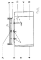
- FIG. 1 shows the vibrating table without any material lying on the actual table 8.
- the table 8 has a rectangular surface.
- a rear stop 5 with passages 5a arranged on the side facing away from the operator, as well as pivotable side stops 4 on the two narrow sides.
- both stops 4 are in their folded-up stop position
- FIG. 2 illustrates the right stop 4 in the folded position, in which it forms a plane with the table 8. Is shaken against two stops, namely the rear stop 5 and one of the side stops 4 by the table 8 is inclined in the direction of these two stops.
- the vibrating table has a portal frame 1 which can be moved in the plane of the table 8 in the direction of the operator side and has an integrated spreading roller 2.
- the vibrating table is provided with a clamping bar 3 which is located above or behind the stop 5 of the support table 8 during the vibrating process. During the spreading operation, this clamping bar 3 is pivoted in front of the stop 5 and clamps the shaken material parallel to the stop 5, in order to prevent the aligned product from shifting when the support table 8 is pivoted horizontally and during the spreading process.
- two cylinders 10 With a housing part 12 movable together with the table 8, two cylinders 10 are connected, the respective adjusting element 13 of which can be moved perpendicular to the table surface.
- the two cylinders 10 are located one behind the other.
- the two adjusting elements 13 receive a bearing element 14 in the area of their upper ends, which is bar-shaped, the adjusting elements 13 engaging on the bearing element 14 in the area of the two bearing element ends.
- two further cylinders 9 are connected to the bearing element 14.
- the adjusting elements 15 of the cylinders 9 are movable parallel to the table surface and perpendicular to the stop 5.
- the stop 5 is shorter at both ends than the table 8, seen in its longitudinal direction, so that the adjusting elements 15 in the Clamping position of the clamping bar 3 are guided past the stop 5 on the outside.
- Air nozzles 6 are connected to the bearing element 14 between the cylinders 9.
- the illustration in FIG. 2 shows two air nozzles 6 of this type which penetrate the two left passages 5a in the rear stop.
- a light barrier 7 is arranged above the blowing nozzle 6 and is also connected to the bearing element 14.
- the light barrier 7 detects a height level which is arranged above the effective area of the air nozzles.
- the air nozzles 6 are individually adjustable and can be activated depending on the format.
- FIG. 2 illustrates that a further bearing element 16 is connected to the bearing element 14, which extends at right angles to the former and parallel to the surface of the table 8.
- This bearing element 16 passes through the right passage 5a in the stop 5 and receives an additional lateral air nozzle 11 in the region of its free end, which is directed towards the left stop 4.
- the table 8 is inclined from the horizontal and set in a vibration movement. If a partial stack of the leafy material 17 to be shaken is now placed on the table 8, the light barrier 7 begins with the air nozzles 6 and any additional lateral nozzle 11 which may be present as well as the clamping bar 3 perpendicular to the table from a basic position minimally above the level of the table 8 to move upwards until the upper edge of the material to be shaken is recognized by the adjustable light barrier 7. Thereupon an alternating movement of the nozzle unit now charged with blown air as well as the light barrier 7 begins.
- the reversal points of this movement sequence are upwards once the upper edge of the stack 17 which builds up further due to the blown air and downwards either the basic position of the blower unit or a time or length-limited, individually adjustable path in the downward direction. If a further sheet layer is now placed on the already existing stack 17, this is recognized by the light barrier 7 and the air nozzles 6 are based on the new top edge of the stack, so that the last sheet layer inserted is always ventilated.
- the switched off air nozzles 6 and 11 together with the clamping bar 3 are raised further by means of the cylinders 10 and, when the clamping bar 3 is positioned above the upper edge of the rear stop 5, the clamping bar 3 is extended by means of the cylinders 9 and in this position the cylinders 10 are retracted until the clamping bar 3 comes to rest on the stack 17.
- the arrangement of the parts when the stack is ventilated is illustrated in FIG. 3, and is illustrated in more detail in FIG. 4 when the stack 17 is clamped.
- FIG. 5 shows a variant in which the air nozzles 6 are integrated directly into the clamping bar 3 by having corresponding air outlet bores.
- the light barrier is mounted on one of the cylinders 9, which move the clamping bar 3 horizontally, so that the detection line of the light barrier 7 is positioned above the effective range of the associated air nozzle 6.
- the bearing element 14 can be omitted.
Abstract
Description
Die Erfindung betrifft einen Rütteltisch zum Rütteln von in Blattlagen vorliegendem Gut, mit mindestens zwei, benachbarten Seiten des Rütteltisches zugeordneten seitlichen Anschlägen für das Gut, wobei der in eine Vibrationsbewegung versetzbare eigentliche Tisch des Rütteltisches aus einer horizontalen Stellung zumindest in Richtung der beiden Anschläge neigbar ist, sowie mit einer auf das Gut auflegbaren Klemmeinrichtung und einer auf das Gut auflegbaren Luftausstreicheinrichtung, die nach dem Klemmen des Gutes von der Klemmstelle weg verfahrbar ist.The invention relates to a vibrating table for vibrating material present in sheet layers, with at least two side stops for the material assigned to adjacent sides of the vibrating table, the actual vibrating table of the vibrating table consisting of a horizontal one Position can be inclined at least in the direction of the two stops, and with a clamping device that can be placed on the goods and an air spreading device that can be placed on the goods, which can be moved away from the clamping point after the goods have been clamped.
Ein Rütteltisch der eingangs genannten Art ist beispielsweise aus dem DE 90 04 711 U1 bekannt. Bei einem solchen Rütteltisch dient die Möglichkeit, den Tisch in Richtung der Anschläge zu neigen, dem Zweck, die auf dem Tisch aufliegenden einzelnen Bögen kantengenau an den Anschlägen auszurichten. Damit sich die Bögen einfach zueinander verschieben können, werden die einzelnen Blattlagen vor dem Rütteln durch Krümmen manuell gelüftet, wobei sich die einzelnen Bögen zueinander verschieben. Betrieben wird der Rütteltisch, indem eine gelüftete Blattlage auf den Tisch aufgelegt und gerüttelt wird und anschließend die nächste gelüftete Blattlage auf die gerüttelte Blattlage aufgelegt wird, um zusammen mit dieser gerüttelt zu werden. Um nach dem Rütteln der Vielzahl von Blattlagen eine unerwünschte Verschiebung des in Stapelform vorliegenden Blattgutes zu verhindern, erfolgt nach dem Klemmen des Gutes mittels des Klemmelementes das Austreichen der Luft durch die von der Klemmstelle weg zum gegenüberliegenden Rand des Blattgutstapels verfahrbare Luftausstreicheinrichtung. Das Ausstreichen der Luft geschieht üblicherweise durch eine auf das Gut absenkbare Walze, die über das Gut abgerollt wird und dabei die Luft aus dem Stapel auspreßt. Der Stapel stellt sich nach dem Entlüften als kompakter Block dar und kann so beispielsweise einer nachfolgenden Schneidstation zugeführt werden. Das Rütteln des Gutes erfolgt in aller Regel dadurch, daß der beidseitig leicht geneigte Tisch, beispielsweise der beidseitig um einen Winkel von 15° aus der Horizontalen geneigte Tisch, in eine Vibrationsbewegung versetzt wird.A vibrating table of the type mentioned is known for example from DE 90 04 711 U1. In the case of such a vibrating table, the possibility of tilting the table in the direction of the stops serves the purpose of aligning the individual sheets lying on the table precisely with the edges of the stops. So that the sheets can easily move relative to one another, the individual sheet layers are manually lifted by bends before shaking, whereby the individual sheets move relative to one another. The vibrating table is operated by placing a ventilated sheet layer on the table and shaking and then placing the next vented sheet layer on the vibrated sheet layer in order to be shaken together with it. In order to prevent an undesirable displacement of the sheet material present in stack form after the plurality of sheet layers have been shaken, the air is spread out after the goods are clamped by means of the clamping element by the air spreading device which can be moved away from the clamping point to the opposite edge of the sheet material stack. The air is usually spread out by means of a roller which can be lowered onto the material and is rolled over the material and in the process squeezes the air out of the stack. After venting, the stack presents itself as a compact block and can, for example, be fed to a subsequent cutting station. The goods are usually shaken by vibrating the table, which is slightly inclined on both sides, for example the table inclined on both sides by an angle of 15 ° from the horizontal.
Aus der EP 0 614 840 A1 ist ferner ein Rütteltisch bekannt, der zumindest im Bereich eines Anschlages Blaseinrichtungen zum seitlichen Einblasen von Luft zwischen die Blattlagen aufweist, ferner eine Verfahreinrichtung, die zumindest dem Verfahren der Klemmeinrichtung parallel zur Tischoberfläche dient.From EP 0 614 840 A1 a vibrating table is also known, which has blowing devices for the lateral blowing in of air between the sheet layers at least in the area of a stop, as well as a moving device which at least corresponds to the method of Clamping device serves parallel to the table surface.
Aus der DE 41 30 322 A1 ist darüber hinaus ein Rütteltisch bekannt, bei dem zusätzlich Blaseinrichtungen zum seitlichen Einblasen von Luft zwischen die Blattlagen vorgesehen sind. Bei diesem Rütteltisch wird das zu rüttelnde Gut wesentlich stärker aus der horizontalen Stellung geneigt, beispielsweise einseitig um einen Winkel von 90° aus der Horizontalen. Um dies zu ermöglichen, ist der Rütteltisch mit einem parallel zur Tischoberfläche angeordneten, ebenen Deckelement zur Aufnahme des Gutes zwischen dem Deckelement und dem Tisch versehen. Die Blaseinrichtungen sind auf zwei gegenüberliegenden Seiten des Deckelementes gehalten, wobei fest angeordnete Stabilisierungsdüsen den Stapel auf voller Breite belüften und die entweichende Luft kontinuierlich ersetzen. Entsprechend dem "Aufschwimmen" der einzelnen Blattlagen wird das Deckelement geöffnet, somit senkrecht zum Tisch wegbewegt, wobei die Stabilisierungsdüsen verhindern, daß der Stapel sich durch das Öffnen des Deckelementes in eine S-Form legen kann. Zusätzlich werden bewegliche Auffächerdüsen, auf die vertikale Stellung des Stapels bezogen, unter und über diesem hin- und herbewegt.A vibrating table is also known from DE 41 30 322 A1, in which blowing devices are additionally provided for the lateral blowing in of air between the sheet layers. With this vibrating table, the material to be vibrated is tilted much more from the horizontal position, for example one-sided at an angle of 90 ° from the horizontal. To make this possible, the vibrating table is provided with a flat cover element arranged parallel to the table surface for receiving the goods between the cover element and the table. The blowing devices are held on two opposite sides of the cover element, with fixed stabilizing nozzles ventilating the stack to its full width and continuously replacing the escaping air. In accordance with the "floating" of the individual sheet layers, the cover element is opened, thus moved away perpendicular to the table, the stabilizing nozzles preventing the stack from being able to lie in an S-shape by opening the cover element. In addition, movable fan nozzles, based on the vertical position of the stack, are moved back and forth under and above it.
Es ist Aufgabe der vorliegenden Erfindung, ein Rütteltisch der eingangs genannten Art so weiter zu bilden, daß mit einfachen baulichen Mitteln das kantengenaue Ausrichten des blättrigen Gutes optimiert wird.It is an object of the present invention to further develop a vibrating table of the type mentioned at the outset such that the simple alignment of the sheet-like material is optimized with simple structural means.
Gelöst wird die Aufgabe bei einem Rütteltisch der eingangs genannten Art dadurch, daß zumindest im Bereich eines Anschlages Blaseinrichtungen zum seitlichen Einblasen von Luft zwischen die Blattlagen angeordnet sind, wobei der den Blaseinrichtungen zugeordnete Anschlag mit Durchlässen für die von den Blaseinrichtungen ausgegebene Blasluft vorgesehen ist, sowie eine erste Verfahreinrichtung zum gleichzeitigen Verfahren der Klemmeinrichtung und der Blaseinrichtungen senkrecht zur Tischoberfläche und eine zweite Verfahreinrichtung, die zumindest dem Verfahren der Klemmeinrichtung parallel zur Tischoberfläche dient, vorgesehen sind.The object is achieved with a vibrating table of the type mentioned at the outset that at least in the area of a stop there are blowing devices for blowing air laterally between the sheet layers, the stop associated with the blowing devices being provided with passages for the blowing air output by the blowing devices, and a first moving device for simultaneously moving the clamping device and the blowing devices perpendicular to the table surface and a second moving device which serves at least for moving the clamping device parallel to the table surface are provided.
Bei dem erfindungsgemäßen Rütteltisch ermöglichen die Blaseinrichtungen eine dauernde Belüftung des zu rüttelnden Gutes, wobei infolge der verfahrbaren Anordnung der Blaseinrichtungen diese zum einen optimal zur jeweils zuletzt aufgelegten, an den Anschlägen auszurichtenden Blattlage positioniert werden können und andererseits die Möglichkeit besteht, die Blaseinrichtungen in eine alternierende Hub-/Senkbewegung relativ zur Tischoberfläche zu versetzen, so daß nur bestimmte Seitenbereiche der Blattlage jeweils mit Blasluft beaufschlagt werden. Ohne nennenswerten baulichen Aufwand kann die Verfahrbarkeit der Blaseinrichtungen erreicht werden, indem diese mit den das Verfahren der Klemmeinrichtung bewirkenden Bauelementen bewegungsschlüssig gekoppelt ist. Dies bedeutet, daß beim Bewegen der Blaseinrichtungen senkrecht zur Tischoberfläche immer die Klemmeinrichtung in dieser Richtung mitbewegt wird und umgekehrt. Die Blaseinrichtungen können dabei beliebig gelagert bzw. positioniert sein, sofern sichergestellt ist, daß diese, bezogen auf die Ausströmrichtung der Blasluft, senkrecht zur Tischoberfläche bewegbar sind. So ist es grundsätzlich denkbar, daß die Blaseinrichtungen in die Klemmeinrichtung integriert sind, womit die Blaseinrichtungen nicht nur senkrecht zur Tischoberfläche, sondern auch parallel zur Tischoberfläche bewegbar sind. Bevorzugt ist die Klemmeinrichtung als Klemmbalken ausgebildet, der auf das Gut auflegbar ist. Der Klemmbalken kann beispielsweise mit Luftaustrittsöffnungen versehen sein. Bei einer solchen Gestaltung des Rütteltisches läßt sich die erfindungsgemäße Wirkung somit auf einfachste Art und Weise dadurch erreichen, daß in die ohnehin vorhandene Klemmeinrichtung, beispielsweise den Klemmbalken, die Blaseinrichtungen integriert sind. Um die Blasluft zwischen das zu rüttelnde Gut einblasen zu können, ist der den Blaseinrichtungen zugeordnete Anschlag mit Durchlässen für die Blasluft versehen. Die Größe der Durchlässe ist nur so groß zu wählen, daß ausreichend Luft durch diese hindurchtreten kann bzw. ein ausreichender Platz zur Aufnahme der Austrittsdüsen der beweglichen Blaseinrichtungen verbleibt.In the vibrating table according to the invention, the blowing devices enable permanent ventilation of the material to be shaken, whereby, owing to the movable arrangement of the blowing devices, they can be optimally positioned on the sheet layer to be positioned last on the stops and, on the other hand, there is the possibility of alternating the blowing devices To move the lifting / lowering movement relative to the table surface, so that only certain side areas of the sheet layer are each subjected to blowing air. The mobility of the blowing devices can be achieved without any appreciable constructional effort, in that it is coupled to the components that effect the movement of the clamping device in a movement-locking manner. This means that when the blowing devices are moved perpendicular to the table surface, the clamping device is always moved in this direction and vice versa. The blowing devices can be mounted or positioned as desired, provided that it is ensured that they can be moved perpendicular to the table surface in relation to the outflow direction of the blowing air. It is basically conceivable that the blowing devices are integrated in the clamping device, whereby the blowing devices are not only movable perpendicular to the table surface, but also parallel to the table surface. The clamping device is preferably designed as a clamping bar which can be placed on the material. The clamping bar can be provided with air outlet openings, for example. With such a design of the vibrating table, the effect according to the invention can thus be achieved in the simplest way by integrating the blowing devices into the clamping device, which is present anyway, for example the clamping bar. In order to be able to blow the blown air between the material to be shaken, the stop assigned to the blower devices is provided with passages for the blown air. The size of the passages is only to be chosen so large that sufficient air can pass through them or that there is sufficient space for receiving the outlet nozzles of the movable blowing devices.
Gemäß einer besonderen Ausführungsform der Erfindung ist vorgesehen, daß oberhalb des wirksamen Bereichs der Blaseinrichtungen eine zusammen mit den Blaseinrichtungen senkrecht zur Tischoberfläche verfahrbare Blatterkennungseinrichtung angeordnet ist. Aufgabe der Blatterkennungseinrichtung ist es, den jeweils obersten Bogen des Stapels zu erkennen und hierüber die Verfahreinrichtung für die Blaseinrichtungen so anzusteuern, daß diese in einer alternierenden Bewegung den jeweils oberen Bereich des Stapels belüften. Wesentlich ist bei, daß die Belüftungseinrichtung in keinem Fall über den Stapel bläst, sondern immer nur seitlich in den Stapel hinein. Die Blatterkennungseinrichtung ist beispielsweise als Lichtschranke ausgebildet. Sie erfaßt die Stapeloberkante gleichfalls durch den Durchlaß im zugeordneten Anschlag des Rütteltisches.According to a special embodiment of the invention it is provided that above the effective area of the blowing devices a sheet detection device which can be moved perpendicular to the table surface together with the blowing devices is arranged. It is the task of the sheet detection device to recognize the uppermost sheet of the stack and to control the moving device for the blowing devices in such a way that they ventilate the upper area of the stack in an alternating movement. It is essential that the ventilation device never blows over the stack, but always only laterally into the stack. The sheet detection device is designed, for example, as a light barrier. It also detects the top edge of the stack through the passage in the associated stop of the vibrating table.
Eine zweckmäßige Ausgestaltung des erfindungsgemäßen Rütteltisches sieht vor, daß die erste Verfahreinrichtung mindestens zwei erste Stellzylinder aufweist, die ein von diesen synchron bewegbares Lagerelement aufnehmen, sowie die zweite Verfahreinrichtung mindestens zwei zweite Stellzylinder aufweist, die im Lagerelement gelagert sind. Im Lagerelement sind zweckmäßig die Blaseinrichtungen und/oder die Blatterkennungseinrichtung gelagert. Bevorzugt sind die Stellelemente der ersten Stellglieder mit unterschiedlichen Geschwindigkeiten verfahrbar. So sollte die Verfahrgeschwindigkeit der Blaseinrichtungen und damit auch der Klemmeinrichtung während des Blasvorganges relativ gering sein, während die Verfahrgeschwindigkeit der Klemmeinrichtung und damit auch der Blaseinrichtungen während des Klemmvorganges, das heißt dem Hochfahren der Klemmeinrichtung, Ausschieben über den Anschlag hinweg und Absenken der Klemmeinrichtung auf den Stapel mit großer Geschwindigkeit erfolgen sollte, um so die Zeiten zum Überführen der Klemmeinrichtung aus deren Ausgangsstellungen in die Klemmstellung und umgekehrt zu minimieren.An expedient embodiment of the vibrating table according to the invention provides that the first displacement device has at least two first actuating cylinders, which receive a bearing element which can be moved synchronously, and the second displacement device has at least two second actuating cylinders, which are mounted in the bearing element. The blowing devices and / or the sheet detection device are expediently mounted in the bearing element. The actuating elements of the first actuators can preferably be moved at different speeds. So the travel speed of the blowing devices and thus also the clamping device during the blowing process should be relatively low, while the travel speed of the clamping device and thus also the blowing devices during the clamping process, that is to say the raising of the clamping device, pushing it out over the stop and lowering the clamping device onto the Stack should be done at high speed so as to minimize the times for transferring the clamping device from its initial positions into the clamping position and vice versa.
Es kann unter Umständen erwünscht sein, die Blattlagen nicht nur im Bereich eines Anschlages, sondern auch im Bereich des weiteren Anschlages zu belüften. Dies kann auf besonders einfache Art und Weise dadurch erreicht werden, indem mit dem Lagerelement ein weiteres Lagerelement verbunden ist, das parallel zur Tischoberfläche und senkrecht zum ersten Lagerelement angeordnet ist, wobei im weiteren Lagerelement zumindest eine weitere Blaseinrichtung gelagert ist. Aufgrund der Verbindung der beiden Lagerelemente werden diese zusammen bewegt, so daß bei entsprechender Anbringung der weiteren Blaseinrichtungen am weiteren Lagerelement die Belüftung auch im anderen Stirnbereich des Blattgutstapels erfolgen kann.Under certain circumstances it may be desirable to ventilate the sheet layers not only in the area of one stop, but also in the area of the further stop. This can be achieved in a particularly simple manner by connecting a further bearing element to the bearing element is arranged parallel to the table surface and perpendicular to the first bearing element, at least one further blowing device being mounted in the further bearing element. Because of the connection of the two bearing elements, these are moved together, so that with appropriate attachment of the further blowing devices to the further bearing element, the ventilation can also take place in the other end region of the stack of sheet material.
Die Erfindung schlägt damit eine kostengünstige, zusätzliche Blaseinrichtung vor, die mit einfachen Mitteln das kantengenaue Ausrichten des blättrigen Gutes optimiert, insbesondere bei stark aneinander haftenden Papiersorten.The invention thus proposes a cost-effective, additional blowing device which, with simple means, optimizes the precise alignment of the leafy material, particularly in the case of strongly adhering types of paper.
Weitere Merkmale der Erfindung sind in den Unteransprüchen, der Beschreibung der Figuren und den Figuren selbst dargestellt, wobei bemerkt wird, daß alle Einzelmerkmale und alle Kombinationen von Einzelmerkmalen erfindungswesentlich sind.Further features of the invention are shown in the subclaims, the description of the figures and the figures themselves, it being noted that all individual features and all combinations of individual features are essential to the invention.
In den Figuren ist die Erfindung schematisch anhand zweier Ausführungsbeispiele dargestellt, ohne auf diese beschränkt zu sein. Es stellt dar:
Figur 1- eine Frontansicht einer ersten Ausführungsform des erfindungsgemäßen Rütteltisches,
Figur 2- eine Draufsicht auf den Rütteltisch nach
Figur 1, in einer gegenüber der Darstellung inFigur 1 modifizierten Betriebsstellung gezeigt, Figur 3- eine Seitenansicht der erfindungsrelevanten Teile des Rütteltisches, veranschaulicht während des Belüftungsvorganges,
Figur 4- eine Seitenansicht der erfindungsrelevanten Teile des Rütteltisches, veranschaulicht während des Klemmvorganges und
Figur 5- eine Seitenansicht der erfindungsrelevanten Teile des Rütteltisches, veranschaulicht für eine modifizierte Ausführung der Blaseinrichtungen, während des Blasvorganges.
- Figure 1
- 2 shows a front view of a first embodiment of the vibrating table according to the invention,
- Figure 2
- 2 shows a plan view of the vibrating table according to FIG. 1, shown in an operating position modified from the illustration in FIG. 1,
- Figure 3
- a side view of the parts of the vibrating table relevant to the invention, illustrated during the ventilation process,
- Figure 4
- a side view of the parts of the vibrating table relevant to the invention, illustrated during the clamping process and
- Figure 5
- a side view of the parts of the vibrating table relevant to the invention, illustrated for a modified version of the blowing devices, during the blowing process.
Figur 1 zeigt den Rütteltisch ohne auf dem eigentlichen Tisch 8 aufliegendes Gut. Der Tisch 8 weist eine rechteckige Oberfläche auf. Im Bereich der Längskante des Tisches 8 ist ein auf der dem Bediener abgewandten Seite angeordneter hinterer Anschlag 5 mit Durchlässen 5a vorgesehen, sowie an den beiden Schmalseiten verschwenkbare seitliche Anschläge 4. In Figur 1 sind beide Anschläge 4 in ihrer hochgeklappten Anschlagsstellung sind, während Figur 2 den rechten Anschlag 4 in der abgeklappten Stellung veranschaulicht, in der dieser eine Ebene mit dem Tisch 8 bildet. Gerüttelt wird gegen zwei Anschläge, nämlich den hinteren Anschlag 5 und einen der seitlichen Anschläge 4, indem der Tisch 8 in Richtung dieser beiden Anschläge geneigt wird.FIG. 1 shows the vibrating table without any material lying on the actual table 8. The table 8 has a rectangular surface. In the area of the longitudinal edge of the table 8 there is a
Der Rütteltisch weist einen in der Ebene des Tisches 8 in Richtung zur Bedienerseite verfahrbaren Portalrahmen 1 mit integrierter Ausstreichwalze 2 auf. Der Rütteltisch ist mit einem Klemmbalken 3 versehen, der sich während des Rüttelvorganges oberhalb bzw. hinter dem Anschlag 5 des Auflagetisches 8 befindet. Beim Ausstreichvorgang wird dieser Klemmbalken 3 vor den Anschlag 5 geschwenkt und klemmt das gerüttelte Gut parallel zum Anschlag 5, um beim schwenken des Auflagetisches 8 in die Horizontale und beim Ausstreichvorgang ein Verschieben des ausgerichteten Gutes zu verhindern.The vibrating table has a
Mit einem mit dem Tisch 8 zusammen beweglichen Gehäuseteil 12 sind zwei Zylinder 10 verbunden, deren jeweiliges Stellelement 13 senkrecht zur Tischoberfläche beweglich ist. In den Figuren 3 und 4 ist jeweils nur ein Zylinder 10 veranschaulicht, die beiden Zylinder 10 befinden sich hintereinander. Die beiden Stellelemente 13 nehmen im Bereich ihrer oberen Enden ein Lagerelement 14 auf, das balkenförmig ausgebildet ist, wobei die Stellelemente 13 im Bereich der beiden Lagerelementenden am Lagerelement 14 angreifen. Gleichfalls im Bereich der Lagerelementenden sind mit dem Lagerelememt 14 zwei weitere Zylinder 9 verbunden. Die Stellelemente 15 der Zylinder 9 sind parallel zur Tischoberfläche und senkrecht zum Anschlag 5 beweglich. Der Anschlag 5 ist beidendig kürzer ausgebildet als der Tisch 8, in dessen Längsrichtung gesehen, sodaß die Stellelemente 15 in der Klemmstellung des Klemmbalkens 3 außen am Anschlag 5 vorbeigeführt sind. Zwischen den Zylindern 9 sind Luftdüsen 6 mit dem Lagerelement 14 verbunden. In der Darstellung der Figur 2 sind zwei derartige Luftdüsen 6 gezeigt, die die beiden linken Durchlässe 5a im hinteren Anschlag durchsetzen. Im Bereich des mittleren Durchlasses 5a ist oberhalb der Blasdüse 6 eine Lichtschranke 7 angeordnet und gleichfalls mit dem Lagerelement 14 verbunden. Die Lichtschranke 7 erfaßt eine Höhenniveau, das oberhalb des wirksamen Bereiches der Luftdüsen angeordnet ist. Die Luftdüsen 6 sind individuell einstellbar und formatabhängig zuschaltbar.With a
Figur 2 veranschaulicht, daß mit dem Lagerelement 14 ein weiteres Lagerelement 16 verbunden ist, das sich rechtwinklig zu erstgenanntem und parallel zur Oberfläche des Tisches 8 erstreckt. Dieses Lagerelement 16 durchsetzt den rechten Durchlaß 5a im Anschlag 5 und nimmt im Bereich seines freien Endes eine zusätzliche seitliche Luftdüse 11 auf, die auf den linken Anschlag 4 zugerichtet ist.FIG. 2 illustrates that a further bearing
Beim Rüttelvorgang wird der Tisch 8 aus der Horizontalen geneigt und in eine Vibrationsbewegung versetzt. Wird nun ein Teilstapels des zu rüttelnden blättrigen Gutes 17 auf den Tisch 8 gelegt, so beginnt die Lichtschranke 7 mit den Luftdüsen 6 und der gegebenenfalls vorhandenen zusätzlichen seitlichen Düse 11 sowie dem Klemmbalken 3 senkrecht zum Tisch aus einer Grundstellung minimal oberhalb der Ebene des Tisches 8 nach oben zu verfahren, bis die Oberkante des zu rüttelnden Gutes von der justierbaren Lichtschranke 7 erkannt ist. Darauf beginnt eine alternierende Bewegung der jetzt mit Blasluft beaufschlagten Düseneinheit sowie der Lichtschranke 7. Die Umkehrpunkte dieses Bewegungsablaufes sind einmal nach oben die sich durch die eingeblasene Luft weiter nach oben aufbauende Oberkante des Stapels 17 und nach unten entweder die Grundstellung der Blaseinheit oder ein zeitlich oder längenmäßig begrenzter, individuell einstellbarer Weg in Abwärtsrichtung. Wird nun eine weitere Blattlage auf den bereits vorhandenen Stapel 17 gelegt, so wird dies von der Lichtschranke 7 erkannt und die Luftdüsen 6 orientieren sich an der neuen Stapeloberkante, so daß immer die zuletzt eingelegte Blattlage belüftet wird.During the shaking process, the table 8 is inclined from the horizontal and set in a vibration movement. If a partial stack of the
Nach dem Belüften werden die abgeschalteten Luftdüsen 6 und 11 zusammen mit dem Klemmbalken 3 mittels der Zylinder 10 weiter angehoben und dann, wenn der Klemmbalken 3 oberhalb der Oberkante des hinteren Anschlages 5 positioniert ist, der Klemmbalken 3 mittels der Zylinder 9 ausgefahren und in dieser Stellung die Zylinder 10 so weit eingefahren, bis der Klemmbalken 3 auf dem Stapel 17 zu liegen kommt. Die Anordnung der Teile beim Belüften des Stapels ist in Figur 3, die beim Klemmen des Stapels 17 in Figur 4 näher veranschaulicht.After ventilation, the switched off
Figur 5 zeigt eine Variante, bei der die Luftdüsen 6 unmittelbar in den Klemmbalken 3 integriert sind, indem dieser entsprechende Luftaustrittsbohrungen aufweist. In diesem Fall ist die Lichtschranke auf einem der den Klemmbalken 3 horizontal verfahrenen Zylinder 9 angebracht, so daß die Erfassungslinie der Lichtschranke 7 oberhalb des Wirkbereiches der zugeordneten Luftdüse 6 positioniert ist. Bei dieser Variante kann das Lagerelement 14 entfallen.FIG. 5 shows a variant in which the
Claims (9)
Applications Claiming Priority (2)
| Application Number | Priority Date | Filing Date | Title |
|---|---|---|---|
| DE19514850 | 1995-04-26 | ||
| DE19514850A DE19514850A1 (en) | 1995-04-26 | 1995-04-26 | Vibrating table |
Publications (3)
| Publication Number | Publication Date |
|---|---|
| EP0739842A2 true EP0739842A2 (en) | 1996-10-30 |
| EP0739842A3 EP0739842A3 (en) | 1997-07-23 |
| EP0739842B1 EP0739842B1 (en) | 2000-10-11 |
Family
ID=7760120
Family Applications (1)
| Application Number | Title | Priority Date | Filing Date |
|---|---|---|---|
| EP96104106A Expired - Lifetime EP0739842B1 (en) | 1995-04-26 | 1996-03-15 | Vibrating table |
Country Status (4)
| Country | Link |
|---|---|
| EP (1) | EP0739842B1 (en) |
| DE (2) | DE19514850A1 (en) |
| ES (1) | ES2152443T3 (en) |
| PT (1) | PT739842E (en) |
Cited By (4)
| Publication number | Priority date | Publication date | Assignee | Title |
|---|---|---|---|---|
| EP2058256A1 (en) | 2007-11-09 | 2009-05-13 | Adolf Mohr Maschinenfabrik GmbH & Co. KG | Device for shaking merchandise in sheets |
| EP2311762A1 (en) | 2009-10-15 | 2011-04-20 | Adolf Mohr Maschinenfabrik GmbH & Co. KG | Device for shaking merchandise in sheets and method for binding such sheets |
| CN115159134A (en) * | 2022-07-28 | 2022-10-11 | 淮滨县建筑工程质量监督管理站 | Board finishing device for house building construction |
| WO2023134988A1 (en) * | 2022-01-14 | 2023-07-20 | Koenig & Bauer Ag | Vibratory device and method for operating a vibratory device |
Families Citing this family (1)
| Publication number | Priority date | Publication date | Assignee | Title |
|---|---|---|---|---|
| DE102019206610B3 (en) * | 2019-05-08 | 2020-04-16 | Heidelberger Druckmaschinen Ag | Printing machine with a stacking device with a vibrating plate |
Citations (3)
| Publication number | Priority date | Publication date | Assignee | Title |
|---|---|---|---|---|
| DE9004711U1 (en) * | 1990-04-25 | 1990-06-21 | Mohr, Wolfgang, 6238 Hofheim, De | |
| DE4130322A1 (en) * | 1991-09-12 | 1993-03-18 | Wolfgang Mohr | Vibratory table for material in sheets - has travelling portal frame with cover and blast nozzles aimed between sheets |
| EP0614840A1 (en) * | 1993-03-09 | 1994-09-14 | Wolfgang Mohr | Vibrating table |
Family Cites Families (1)
| Publication number | Priority date | Publication date | Assignee | Title |
|---|---|---|---|---|
| DE3635390A1 (en) * | 1986-10-17 | 1988-04-21 | Rauma Repola Oy | Hydraulic cylinder |
-
1995
- 1995-04-26 DE DE19514850A patent/DE19514850A1/en not_active Withdrawn
-
1996
- 1996-03-15 PT PT96104106T patent/PT739842E/en unknown
- 1996-03-15 EP EP96104106A patent/EP0739842B1/en not_active Expired - Lifetime
- 1996-03-15 DE DE59605977T patent/DE59605977D1/en not_active Expired - Fee Related
- 1996-03-15 ES ES96104106T patent/ES2152443T3/en not_active Expired - Lifetime
Patent Citations (3)
| Publication number | Priority date | Publication date | Assignee | Title |
|---|---|---|---|---|
| DE9004711U1 (en) * | 1990-04-25 | 1990-06-21 | Mohr, Wolfgang, 6238 Hofheim, De | |
| DE4130322A1 (en) * | 1991-09-12 | 1993-03-18 | Wolfgang Mohr | Vibratory table for material in sheets - has travelling portal frame with cover and blast nozzles aimed between sheets |
| EP0614840A1 (en) * | 1993-03-09 | 1994-09-14 | Wolfgang Mohr | Vibrating table |
Cited By (5)
| Publication number | Priority date | Publication date | Assignee | Title |
|---|---|---|---|---|
| EP2058256A1 (en) | 2007-11-09 | 2009-05-13 | Adolf Mohr Maschinenfabrik GmbH & Co. KG | Device for shaking merchandise in sheets |
| EP2311762A1 (en) | 2009-10-15 | 2011-04-20 | Adolf Mohr Maschinenfabrik GmbH & Co. KG | Device for shaking merchandise in sheets and method for binding such sheets |
| WO2023134988A1 (en) * | 2022-01-14 | 2023-07-20 | Koenig & Bauer Ag | Vibratory device and method for operating a vibratory device |
| CN115159134A (en) * | 2022-07-28 | 2022-10-11 | 淮滨县建筑工程质量监督管理站 | Board finishing device for house building construction |
| CN115159134B (en) * | 2022-07-28 | 2023-10-27 | 淮滨县建筑工程质量监督管理站 | Board finishing device for house construction |
Also Published As
| Publication number | Publication date |
|---|---|
| EP0739842A3 (en) | 1997-07-23 |
| EP0739842B1 (en) | 2000-10-11 |
| ES2152443T3 (en) | 2001-02-01 |
| PT739842E (en) | 2001-04-30 |
| DE59605977D1 (en) | 2000-11-16 |
| DE19514850A1 (en) | 1996-10-31 |
Similar Documents
| Publication | Publication Date | Title |
|---|---|---|
| EP0056874B1 (en) | Apparatus for cutting paper and the like | |
| EP0614840B1 (en) | Vibrating table | |
| DE4214049C2 (en) | ||
| EP1997595B1 (en) | Cutting device for cutting strip material, in particular textile or steel rope strips | |
| DE2924017C2 (en) | Device for sewing an annular elastic band onto a tubular workpiece on a sewing machine | |
| EP0654349A1 (en) | Cassette for automatically exchanging printing plates in a printing machine | |
| EP1702764A2 (en) | Method and device for manufacturing book covers with rounded edges | |
| EP0924057A2 (en) | Method and apparatus for making two bags simultaneously | |
| EP1018408B1 (en) | Guillotine-type machine for cutting stacked sheet material | |
| EP0418529B1 (en) | Apparatus for trilateral trimming of signatures | |
| EP0436506A1 (en) | Device for squaring-up piles | |
| DE4130322C2 (en) | ||
| DE2942883C2 (en) | Device for closing the bottom of a rectangular erected folding box | |
| EP0739842B1 (en) | Vibrating table | |
| DE2441459A1 (en) | ARCH EXTENSION ON PRINTING MACHINES WITH ARCH HOLDING DEVICE | |
| DE19508667A1 (en) | Device for creating and stacking cut stacks of sheet material | |
| DE19842344C2 (en) | Method of transporting sheets and sheet processing machine operating according to the method | |
| CH694504A5 (en) | A method for cutting metal sheets to metal strips and cutting device for its implementation. | |
| DE4004461C2 (en) | Device for aligning sheets to the leading edge | |
| DE102009031117B3 (en) | Apparatus and method for the stacked storage of sheet-shaped substrates | |
| WO2008101706A1 (en) | Closing machine | |
| DE3220917C2 (en) | Method for dividing partial stacks from an overall stack and for depositing each partial stack in a flaky position | |
| DE102017109695A1 (en) | sawing | |
| DE2654000B2 (en) | Machine for breaking out of use | |
| DE7728960U1 (en) | DEVICE FOR PUSHING SHEETS OF SHEETS INTO A STACK |
Legal Events
| Date | Code | Title | Description |
|---|---|---|---|
| PUAI | Public reference made under article 153(3) epc to a published international application that has entered the european phase |
Free format text: ORIGINAL CODE: 0009012 |
|
| AK | Designated contracting states |
Kind code of ref document: A2 Designated state(s): CH DE ES FR GB IT LI NL PT SE |
|
| PUAL | Search report despatched |
Free format text: ORIGINAL CODE: 0009013 |
|
| AK | Designated contracting states |
Kind code of ref document: A3 Designated state(s): CH DE ES FR GB IT LI NL PT SE |
|
| 17P | Request for examination filed |
Effective date: 19970625 |
|
| 17Q | First examination report despatched |
Effective date: 19981203 |
|
| GRAG | Despatch of communication of intention to grant |
Free format text: ORIGINAL CODE: EPIDOS AGRA |
|
| GRAG | Despatch of communication of intention to grant |
Free format text: ORIGINAL CODE: EPIDOS AGRA |
|
| GRAH | Despatch of communication of intention to grant a patent |
Free format text: ORIGINAL CODE: EPIDOS IGRA |
|
| 17Q | First examination report despatched |
Effective date: 19981203 |
|
| GRAH | Despatch of communication of intention to grant a patent |
Free format text: ORIGINAL CODE: EPIDOS IGRA |
|
| GRAA | (expected) grant |
Free format text: ORIGINAL CODE: 0009210 |
|
| AK | Designated contracting states |
Kind code of ref document: B1 Designated state(s): CH DE ES FR GB IT LI NL PT SE |
|
| REG | Reference to a national code |
Ref country code: CH Ref legal event code: EP |
|
| REF | Corresponds to: |
Ref document number: 59605977 Country of ref document: DE Date of ref document: 20001116 |
|
| REG | Reference to a national code |
Ref country code: CH Ref legal event code: NV Representative=s name: ISLER & PEDRAZZINI AG |
|
| GBT | Gb: translation of ep patent filed (gb section 77(6)(a)/1977) |
Effective date: 20001206 |
|
| ITF | It: translation for a ep patent filed |
Owner name: MODIANO & ASSOCIATI S.R.L. |
|
| REG | Reference to a national code |
Ref country code: ES Ref legal event code: FG2A Ref document number: 2152443 Country of ref document: ES Kind code of ref document: T3 |
|
| ET | Fr: translation filed | ||
| PGFP | Annual fee paid to national office [announced via postgrant information from national office to epo] |
Ref country code: GB Payment date: 20010316 Year of fee payment: 6 Ref country code: FR Payment date: 20010316 Year of fee payment: 6 |
|
| PGFP | Annual fee paid to national office [announced via postgrant information from national office to epo] |
Ref country code: SE Payment date: 20010319 Year of fee payment: 6 |
|
| PGFP | Annual fee paid to national office [announced via postgrant information from national office to epo] |
Ref country code: ES Payment date: 20010323 Year of fee payment: 6 Ref country code: CH Payment date: 20010323 Year of fee payment: 6 |
|
| PGFP | Annual fee paid to national office [announced via postgrant information from national office to epo] |
Ref country code: NL Payment date: 20010326 Year of fee payment: 6 |
|
| PGFP | Annual fee paid to national office [announced via postgrant information from national office to epo] |
Ref country code: PT Payment date: 20010329 Year of fee payment: 6 |
|
| REG | Reference to a national code |
Ref country code: PT Ref legal event code: SC4A Free format text: AVAILABILITY OF NATIONAL TRANSLATION Effective date: 20010109 |
|
| PGFP | Annual fee paid to national office [announced via postgrant information from national office to epo] |
Ref country code: DE Payment date: 20010721 Year of fee payment: 6 |
|
| PLBE | No opposition filed within time limit |
Free format text: ORIGINAL CODE: 0009261 |
|
| STAA | Information on the status of an ep patent application or granted ep patent |
Free format text: STATUS: NO OPPOSITION FILED WITHIN TIME LIMIT |
|
| 26N | No opposition filed | ||
| REG | Reference to a national code |
Ref country code: GB Ref legal event code: IF02 |
|
| PG25 | Lapsed in a contracting state [announced via postgrant information from national office to epo] |
Ref country code: GB Free format text: LAPSE BECAUSE OF NON-PAYMENT OF DUE FEES Effective date: 20020315 |
|
| PG25 | Lapsed in a contracting state [announced via postgrant information from national office to epo] |
Ref country code: SE Free format text: LAPSE BECAUSE OF NON-PAYMENT OF DUE FEES Effective date: 20020316 Ref country code: ES Free format text: LAPSE BECAUSE OF NON-PAYMENT OF DUE FEES Effective date: 20020316 |
|
| PG25 | Lapsed in a contracting state [announced via postgrant information from national office to epo] |
Ref country code: LI Free format text: LAPSE BECAUSE OF NON-PAYMENT OF DUE FEES Effective date: 20020331 Ref country code: CH Free format text: LAPSE BECAUSE OF NON-PAYMENT OF DUE FEES Effective date: 20020331 |
|
| PG25 | Lapsed in a contracting state [announced via postgrant information from national office to epo] |
Ref country code: PT Free format text: LAPSE BECAUSE OF NON-PAYMENT OF DUE FEES Effective date: 20020930 |
|
| PG25 | Lapsed in a contracting state [announced via postgrant information from national office to epo] |
Ref country code: NL Free format text: LAPSE BECAUSE OF NON-PAYMENT OF DUE FEES Effective date: 20021001 Ref country code: DE Free format text: LAPSE BECAUSE OF NON-PAYMENT OF DUE FEES Effective date: 20021001 |
|
| EUG | Se: european patent has lapsed |
Ref document number: 96104106.8 |
|
| GBPC | Gb: european patent ceased through non-payment of renewal fee |
Effective date: 20020315 |
|
| REG | Reference to a national code |
Ref country code: CH Ref legal event code: PL |
|
| PG25 | Lapsed in a contracting state [announced via postgrant information from national office to epo] |
Ref country code: FR Free format text: LAPSE BECAUSE OF NON-PAYMENT OF DUE FEES Effective date: 20021129 |
|
| NLV4 | Nl: lapsed or anulled due to non-payment of the annual fee |
Effective date: 20021001 |
|
| REG | Reference to a national code |
Ref country code: PT Ref legal event code: MM4A Free format text: LAPSE DUE TO NON-PAYMENT OF FEES Effective date: 20020930 |
|
| REG | Reference to a national code |
Ref country code: FR Ref legal event code: ST |
|
| REG | Reference to a national code |
Ref country code: ES Ref legal event code: FD2A Effective date: 20030410 |
|
| PG25 | Lapsed in a contracting state [announced via postgrant information from national office to epo] |
Ref country code: IT Free format text: LAPSE BECAUSE OF NON-PAYMENT OF DUE FEES Effective date: 20050315 |