EP0739449B1 - Vorrichtung zum führen und zentrieren eines maschinenelementes - Google Patents
Vorrichtung zum führen und zentrieren eines maschinenelementes Download PDFInfo
- Publication number
- EP0739449B1 EP0739449B1 EP95935790A EP95935790A EP0739449B1 EP 0739449 B1 EP0739449 B1 EP 0739449B1 EP 95935790 A EP95935790 A EP 95935790A EP 95935790 A EP95935790 A EP 95935790A EP 0739449 B1 EP0739449 B1 EP 0739449B1
- Authority
- EP
- European Patent Office
- Prior art keywords
- spring
- central axis
- elements
- parts
- main spring
- Prior art date
- Legal status (The legal status is an assumption and is not a legal conclusion. Google has not performed a legal analysis and makes no representation as to the accuracy of the status listed.)
- Expired - Lifetime
Links
- 230000033001 locomotion Effects 0.000 claims abstract description 26
- 238000004519 manufacturing process Methods 0.000 description 6
- 238000005299 abrasion Methods 0.000 description 2
- 239000000314 lubricant Substances 0.000 description 2
- 239000000463 material Substances 0.000 description 2
- 238000007789 sealing Methods 0.000 description 2
- 230000007704 transition Effects 0.000 description 2
- 238000004804 winding Methods 0.000 description 2
- 229910000639 Spring steel Inorganic materials 0.000 description 1
- 238000010521 absorption reaction Methods 0.000 description 1
- 230000006978 adaptation Effects 0.000 description 1
- 238000005452 bending Methods 0.000 description 1
- 230000009286 beneficial effect Effects 0.000 description 1
- 238000000576 coating method Methods 0.000 description 1
- 239000002826 coolant Substances 0.000 description 1
- 230000001419 dependent effect Effects 0.000 description 1
- 238000011161 development Methods 0.000 description 1
- 230000018109 developmental process Effects 0.000 description 1
- 238000006073 displacement reaction Methods 0.000 description 1
- 230000005489 elastic deformation Effects 0.000 description 1
- 230000002349 favourable effect Effects 0.000 description 1
- 238000003754 machining Methods 0.000 description 1
- 230000007257 malfunction Effects 0.000 description 1
- 230000010355 oscillation Effects 0.000 description 1
- 125000006850 spacer group Chemical group 0.000 description 1
- 238000003860 storage Methods 0.000 description 1
Images



Classifications
-
- H—ELECTRICITY
- H02—GENERATION; CONVERSION OR DISTRIBUTION OF ELECTRIC POWER
- H02K—DYNAMO-ELECTRIC MACHINES
- H02K33/00—Motors with reciprocating, oscillating or vibrating magnet, armature or coil system
- H02K33/02—Motors with reciprocating, oscillating or vibrating magnet, armature or coil system with armatures moved one way by energisation of a single coil system and returned by mechanical force, e.g. by springs
-
- F—MECHANICAL ENGINEERING; LIGHTING; HEATING; WEAPONS; BLASTING
- F04—POSITIVE - DISPLACEMENT MACHINES FOR LIQUIDS; PUMPS FOR LIQUIDS OR ELASTIC FLUIDS
- F04B—POSITIVE-DISPLACEMENT MACHINES FOR LIQUIDS; PUMPS
- F04B35/00—Piston pumps specially adapted for elastic fluids and characterised by the driving means to their working members, or by combination with, or adaptation to, specific driving engines or motors, not otherwise provided for
- F04B35/04—Piston pumps specially adapted for elastic fluids and characterised by the driving means to their working members, or by combination with, or adaptation to, specific driving engines or motors, not otherwise provided for the means being electric
- F04B35/045—Piston pumps specially adapted for elastic fluids and characterised by the driving means to their working members, or by combination with, or adaptation to, specific driving engines or motors, not otherwise provided for the means being electric using solenoids
-
- F—MECHANICAL ENGINEERING; LIGHTING; HEATING; WEAPONS; BLASTING
- F04—POSITIVE - DISPLACEMENT MACHINES FOR LIQUIDS; PUMPS FOR LIQUIDS OR ELASTIC FLUIDS
- F04B—POSITIVE-DISPLACEMENT MACHINES FOR LIQUIDS; PUMPS
- F04B39/00—Component parts, details, or accessories, of pumps or pumping systems specially adapted for elastic fluids, not otherwise provided for in, or of interest apart from, groups F04B25/00 - F04B37/00
- F04B39/04—Measures to avoid lubricant contaminating the pumped fluid
- F04B39/041—Measures to avoid lubricant contaminating the pumped fluid sealing for a reciprocating rod
- F04B39/045—Labyrinth-sealing between piston and cylinder
-
- H—ELECTRICITY
- H02—GENERATION; CONVERSION OR DISTRIBUTION OF ELECTRIC POWER
- H02K—DYNAMO-ELECTRIC MACHINES
- H02K33/00—Motors with reciprocating, oscillating or vibrating magnet, armature or coil system
-
- H—ELECTRICITY
- H02—GENERATION; CONVERSION OR DISTRIBUTION OF ELECTRIC POWER
- H02K—DYNAMO-ELECTRIC MACHINES
- H02K7/00—Arrangements for handling mechanical energy structurally associated with dynamo-electric machines, e.g. structural association with mechanical driving motors or auxiliary dynamo-electric machines
- H02K7/08—Structural association with bearings
Definitions
- the invention relates to a device for guiding and centering of a machine element, which oscillating linear movements in the direction of its central axis, the machine element on two in the direction of the central axis, spaced guides, in is housed in a housing.
- DE-A1-30 30 711 is a vibration compressor known which is intended for refrigerators.
- At this known vibration compressor is powered by a drive winding, which is fed with alternating current, and a magnet with a magnetic pole in a piston translational, oscillating movements offset.
- This Piston is in a cylinder liner, which is a sliding guide forms, stored.
- Pistons which oscillate linear movements along a central axis perform, also occur with free piston engines, e.g. Stirling engines on.
- free piston engines e.g. Stirling engines on.
- Similar ones are known Solutions applied to the known oscillating Compressor have been explained. The same occur Difficulties with non-contact sealing surfaces between Piston and cylinder wall, if at all, only with a lot great effort and correspondingly high costs can be achieved can. Because of the difficult operating conditions occurs nevertheless abrasion between moving machine elements on, causing the operation of such free piston engines badly disturbed and the maintenance-free life is significantly reduced.
- Stirling Engines G.
- the device should be simple and be constructed maintenance-free and with constant precision and manufactured and installed with constant characteristics can be.
- the device is intended to enable linearly oscillating moving machine elements and to run lubricant-free in other machine elements, e.g. as a piston / cylinder or armature / stator arrangement for linear motors.
- each of the two exists spaced guides from several plate-shaped spring elements.
- the proposed arrangement the guides with the spring elements provides the Advantage that the machine element which is oscillating Performs linear movements exactly on its central axis centered and guided.
- the guides have no parts on which move against each other and slide wear are subject.
- the machine element is created by the two Guides so guided and centered that it is opposite others Relative movement of machine elements without contact can perform. This e.g. in a piston / cylinder arrangement with a pump or a linear motor, or with electrical Linear generators with oscillating movement.
- the Spring elements of the individual guides are on one level arranged, which is approximately at right angles to the central axis of the stands oscillating moving machine element.
- the main spring parts which are plate-shaped are trained. This arrangement of the main spring parts leaves a calculation of the movement and spring data in known Way too, so that the movements of the machine element have it determined exactly. Outside the long main spring parts are arranged with shorter auxiliary spring parts, and at right angles to the main spring parts, so that these auxiliary spring parts are roughly parallel to the central axis run. The connection of the auxiliary spring parts with the main spring parts takes place via an additional connecting element, which with appropriate fasteners for fixed Connection of the ends of the main and auxiliary spring parts Is provided.
- each spring element from several individual spring parts enables adaptation to different requirements and has the significant advantage that no parts of the spring elements deformed during manufacture, for example, have to be turned.
- the plate-shaped Design of the individual spring element parts lets precise machining to the desired dimensions at any time, e.g. by grinding too.
- the main and auxiliary spring parts are normally flat plates.
- each guide expediently arranged centrally symmetrically, so that from the central axis in the plane of the guide four, extend six or more spring element parts radially outwards. Odd numbers of spring element parts in the plane the tour is possible, each expediently includes Spring element, however, a main spring part, which itself extends symmetrically on both sides of the central axis. Thereby, that between the spring elements, which lie in one plane, the same angles are included, results the advantage that the machine element on the central axis is centered exactly symmetrically.
- the stiffness ratio can be for example, not just by changing the dimensions of the change plate-shaped spring parts, but also by that at least two auxiliary spring parts or main spring parts spaced parallel to each other, or that Auxiliary and main spring parts are designed in this way. Becomes no change in the spring constant desired, so can in a guide in two spaced apart Levels arranged two groups of plate-shaped spring elements be. This leads to an increase in the load capacity the corresponding leadership with approximately the same Stiffness ratio. With all these different Arrangements and embodiments can always be the same Basic elements of main spring parts, auxiliary spring parts and Fasteners are used so that the calculation bases be simplified, and also manufacturing the individual parts is made considerably easier. Another The advantage is that the main spring part of each Spring elements can be formed in one or two parts.
- the guide is arranged at the end of an axis, it can be advantageous to form the main spring parts in one piece, since it is then using a central connecting element can be connected to the axis.
- the leadership arranged somewhere in the axis area of the machine element, so it is often appropriate to the main spring parts in two parts to execute, and then those directed against the central axis inner ends of the main spring parts by corresponding To connect fastening devices with the axis.
- specially designed clamping elements are also known non-positive connections can be used.
- the compressor 1 shown in Fig. 1 has a boxer arrangement via two pistons 3, 4, which with cylinders 5, 6 work together. These cylinders 5, 6 are part of a Housing 10 of the compressor 1.
- the two pistons 3, 4 are each arranged at the ends of a piston rod 7, the Piston rod 7 and the pistons 3, 4 a central axis 2, which at the same time forms the longitudinal axis of the housing 10.
- a magnet armature 9, which is from a coil 8 is surrounded.
- This coil 8 is connected via line 22 Alternating current fed, whereby the magnet armature 9 along the central axis 2 in the direction of arrows 23 in oscillating Linear movements is offset.
- the pistons 3 and 4 are also in oscillating working movements transferred.
- pressure lines 19 and suction lines 20 arranged with valves 21, via which the suction and ejection of a pressure medium is controlled.
- the piston rod 7 and thus the piston 3 and 4, and the magnet armature 9 are on guides 11, 12 guided and centered.
- These guides 11, 12 are on two levels 13, 14 aligned, which are approximately at right angles to the central axis 2.
- the two levels 13, 14 and so the two guides 11, 12 are in the direction of the central axis 2 arranged at a distance from each other, this Distance due to the storage conditions, as well as the constructive Conditions of the compressor is determined.
- Each of the two guides 11, 12 consists of several spring elements 15.
- These spring elements 15 consist of a two-part long main spring part 16 and two short Auxiliary spring parts 17, which at the outer ends 24, 25 of the Main spring part 16 rigidly attached and to the housing 10 are connected.
- the auxiliary spring parts 17 are approximately arranged at right angles to the main spring part 16 and extend thus roughly parallel to the central axis 2.
- the rigid connection between the outer ends 24, 25 of the main spring part 16 and the auxiliary spring parts 17 is by means of connecting elements 18 manufactured.
- the spring elements 15 are on the one hand via the auxiliary spring parts 17 and the fastening elements 26 firmly with the housing 10 and on the other hand via the main spring parts 16 and a flange 27 and clamping elements 28 with the oscillating machine element, i.e. the piston rod 7 and the pistons 3, 4 firmly connected.
- the two guides 11, 12 are of exactly the same design, however as can be seen from the figure, arranged mirror-inverted.
- each guide 11, 12 formed spring system is designed so that the stiffness towards levels 13, 14 is at least 100 times greater than its stiffness in the direction of the central axis 2. In the case shown in FIG. 1 An example is the stiffness across the central axis 2 approx. 200 times higher than in the direction of the central axis 2.
- Spring parts made of hardened spring steel are used for this with a thickness of 1.18 mm. 11, 12 per tour two spring elements 15 are present, which are perpendicular to each other are arranged and each of two main spring parts 16th and two auxiliary spring parts 17 exist.
- the main spring parts 16 have a length of approx. 13 cm and the auxiliary spring parts a length of about 2.2 cm. So that a piston stroke of 20 mm possible.
- the piston diameter is 45 mm and Oscillation frequency 50 vibrations per minute.
- Fig. 2 shows the connection area between the outer End 24 of a long main spring part 16 and a short one Auxiliary spring part 17 in an enlarged view.
- the connecting element 18 is designed as an angle element and has two positioning surfaces 30, 31, which in one are at right angles to each other. These positioning surfaces 30, 31 serve as supports for the end regions of the main spring part 16, and the auxiliary spring part 17. In the shown Example, the positioning surface 31 also serves as Stop surface for the outer edge 35 of the long main spring part 16. The outer edge of the auxiliary spring part 17 is in turn pushed against the surface of the main spring part, so that the positions of the two spring parts 16, 17 within of the connecting element 18 are precisely determined.
- the main spring part 16 and the auxiliary spring part 17 are over the connecting element 18 and corresponding clamping devices 32, 33 non-positively connected.
- the adhesion is generated by rivets 34 in the example shown, these Connection can also be replaced by a screw connection can.
- the transition areas from the clamping area to the free area of the spring parts 16, 17 are in a known manner designed so that no damage to the spring elements occur, e.g. by rounding off the edges or suitable Coatings of the clamping plates 32, 33, or the connecting element 18th
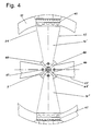
- FIGS. 3 and 4 show a guide 11 and 12, respectively in principle corresponds to the arrangements according to FIGS. 1 and 2.
- levels 14, 40 there are two at a distance from each other on each guide arranged levels 14, 40 in which the long Main spring elements 16 ', 16 "of the spring elements 15 are arranged are.
- the two levels 14, 40 run parallel to each other and approximately at right angles to the central axis 2 of the piston rod 7. From Fig. 4 it can be seen that in each of the Levels 14, 40 two spring elements 15 are arranged, which are perpendicular to each other, and in which between the Main spring parts 16 are included the same angle.
- Each of the spring elements 15 consists of two main spring parts 16 ', 16 ", two auxiliary spring parts 17 and two connecting elements 18.
- the connecting elements 18 opposite ends of the short auxiliary spring parts 17 are by means of Fastening elements 41, 42 and screws 43 on the housing 10 rigidly attached to the machine.
- the piston rod 7, which Part of the linear and oscillating moving machine element has a flange 27, as well as a Clamping element 28, which connects the inner ends 44 the main spring parts 16 ', 16 "is used with the flange 27.
- Die short auxiliary spring parts 17 are made of flat, rectangular Plates formed.
- the main spring parts 16 are trapezoidal and wider towards the outer end 24 than at inner end 44.
- the shape of the spring parts 16, 17 is known in the Way by the desired spring characteristics certainly.
- Ribs 45 are arranged on the centering plates 48, which stop surfaces 46 for the inner ends 44 of the Form main spring parts 16 ', 16 ". These ribs 45 and the corresponding stop surfaces 46 and the corresponding one Shape of the inner ends 44 of the main spring parts 16, is their position opposite the centering plates 48 or the piston rod 7 exactly determined. In this position the inner ends 44 of the main spring parts 16 with Using the two centering plates 48, the clamping element 28, and a spacer 49 and clamped by screws 47 and held.
- This arrangement shown in Figs. 3 and 4 A guide 11 or 12 can have greater longitudinal and transverse forces record, but leaves the same movements as described for Fig. 1.
- the two-part main spring parts 16 is in particular useful where on the central axis 2 before and 11 or 12 further machine elements behind the guides are arranged, which a plugging of continuous Do not allow spring elements 15 on the piston rod 7. in the The production of the main spring parts will also continue 16 facilitated because they have smaller dimensions, and if necessary, individual parts of a spring element 15 can be replaced are.
- Fig. 5 shows a guide in which the oscillating Machine element or the piston rod 7 stored at the end and is led.
- the tour consists of two Spring elements 15, which are perpendicular to each other and in turn arranged in a plane perpendicular to the central axis 2 are.
- Each of the spring elements 15 consists of a continuous main spring part 16, which the central axis 2nd cuts radially.
- At the outer ends 24 of the main spring parts 16 in turn connecting elements 18 are arranged, however, this in the example shown in Fig. 5 Support and positioning surfaces for two parallel, have short auxiliary spring parts 17.
- each of the Main spring parts 16 have a bore 51 which on the end pin 52 the piston rod 7 fits positively.
- clamping elements 53, 54 On both sides of the two main spring parts 16 there are clamping elements 53, 54, which are disc-shaped.
- the end pin 52 For positioning is a stop flange 55 on the piston rod 7 formed, and the end pin 52 has a screw 56 with which the clamping elements 53, 54 and the main spring parts 16 can be clamped and clamped.
- the main spring parts 16 are turned away Pages 57, 58 of the clamping elements 53, 54 with central Depressions 62, 62 'and on these sides 57, 58 then additional tensioning washers 59, 60 are arranged.
- the clamping force generated by the screw 56 by elastic deformation of the tensioning washers 59, 60 directed to the outer regions of the clamping elements 53, 54, and so that the main spring parts 16 in these outer areas perfectly tensioned.
- the arrangement of parallel auxiliary spring parts shown in FIG. 5 17 enables a significant increase in Lateral stiffness, in particular through an enlargement of the distance 63 between the spring parts 17 is positively influenced can be.
- the arrangement of an auxiliary spring part 17 according to FIGS. 1 and 2 represents the simplest embodiment represents.
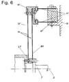
- FIG. 6 shows a further embodiment of an inventive one Guide shown, with in each spring element 15th both the main spring parts 16 and the auxiliary spring parts 17 arranged in pairs parallel and at a distance from each other are.
- the connection of the inner ends 44 of the main spring parts 16 with the flange 27 of the piston rod 7 takes place in the same Way, as described to FIGS. 3 and 4.
- the connecting element 18 between the outer ends of the main spring parts 16 and the abutting ends of the auxiliary spring parts 17 is designed accordingly and has contact surfaces for the arrangement of the parallel springs in pairs.
- the auxiliary spring parts 17 with the housing 10 are corresponding Fastening and tensioning elements 61 available.
- the Design of the guide with parallel springs 16 leads to a spring characteristic symmetrical in both longitudinal directions of movement with a correspondingly more favorable voltage curve.
- the simple spring shows because of the bending and force relationships in the clamping areas for the forward or Backward movement of the machine element is not the same Spring characteristic. In relation to the zero point the positive and negative characteristics of the single spring not symmetrical.
Landscapes
- Engineering & Computer Science (AREA)
- Power Engineering (AREA)
- Mechanical Engineering (AREA)
- General Engineering & Computer Science (AREA)
- Compressors, Vaccum Pumps And Other Relevant Systems (AREA)
- Springs (AREA)
- Electromagnetic Pumps, Or The Like (AREA)
- Catching Or Destruction (AREA)
- Sewing Machines And Sewing (AREA)
- Pinball Game Machines (AREA)
- Automatic Control Of Machine Tools (AREA)
- Support Of The Bearing (AREA)
- Actuator (AREA)
- Grinding Of Cylindrical And Plane Surfaces (AREA)
- Knitting Machines (AREA)
- Control Of Vending Devices And Auxiliary Devices For Vending Devices (AREA)
Applications Claiming Priority (3)
| Application Number | Priority Date | Filing Date | Title |
|---|---|---|---|
| CH339894 | 1994-11-14 | ||
| CH3398/94 | 1994-11-14 | ||
| PCT/CH1995/000258 WO1996015367A1 (de) | 1994-11-14 | 1995-11-09 | Vorrichtung zum führen und zentrieren eines maschinenelementes |
Publications (2)
| Publication Number | Publication Date |
|---|---|
| EP0739449A1 EP0739449A1 (de) | 1996-10-30 |
| EP0739449B1 true EP0739449B1 (de) | 1998-05-20 |
Family
ID=4255124
Family Applications (1)
| Application Number | Title | Priority Date | Filing Date |
|---|---|---|---|
| EP95935790A Expired - Lifetime EP0739449B1 (de) | 1994-11-14 | 1995-11-09 | Vorrichtung zum führen und zentrieren eines maschinenelementes |
Country Status (11)
| Country | Link |
|---|---|
| US (1) | US5779455A (da) |
| EP (1) | EP0739449B1 (da) |
| JP (1) | JP3844359B2 (da) |
| CN (1) | CN1071411C (da) |
| AT (1) | ATE166432T1 (da) |
| AU (1) | AU693275B2 (da) |
| CA (1) | CA2181183A1 (da) |
| DE (1) | DE59502252D1 (da) |
| DK (1) | DK0739449T3 (da) |
| ES (1) | ES2117880T3 (da) |
| WO (1) | WO1996015367A1 (da) |
Cited By (2)
| Publication number | Priority date | Publication date | Assignee | Title |
|---|---|---|---|---|
| DE102009047743A1 (de) * | 2009-12-09 | 2011-06-16 | BSH Bosch und Siemens Hausgeräte GmbH | Verdichter mit einem Tragegestell |
| DE102009047744A1 (de) * | 2009-12-09 | 2011-06-16 | BSH Bosch und Siemens Hausgeräte GmbH | Verdichter mit einer Pumpkammer |
Families Citing this family (47)
| Publication number | Priority date | Publication date | Assignee | Title |
|---|---|---|---|---|
| EP1020013B1 (en) * | 1997-10-04 | 2004-04-28 | Z & D Limited | Linear motor compressor |
| DE19839464C2 (de) * | 1998-08-29 | 2001-07-05 | Contitech Formteile Gmbh | Elektrodynamischer Aktuator mit schwingendem Feder-Masse-System |
| BR9803560A (pt) * | 1998-09-09 | 2000-04-18 | Brasil Compressores Sa | Compressor alternativo de acionamento por motor linear. |
| US6273688B1 (en) * | 1998-10-13 | 2001-08-14 | Matsushita Electric Industrial Co., Ltd. | Linear compressor |
| US6129527A (en) * | 1999-04-16 | 2000-10-10 | Litton Systems, Inc. | Electrically operated linear motor with integrated flexure spring and circuit for use in reciprocating compressor |
| JP3370653B2 (ja) * | 2000-01-06 | 2003-01-27 | 株式会社テクノ高槻 | 電磁振動型ポンプおよびその製法 |
| US6663361B2 (en) * | 2000-04-04 | 2003-12-16 | Baker Hughes Incorporated | Subsea chemical injection pump |
| TW504546B (en) * | 2000-10-17 | 2002-10-01 | Fisher & Amp Paykel Ltd | A linear compressor |
| US6746212B2 (en) * | 2002-03-22 | 2004-06-08 | Intel Corporation | High efficiency pump for liquid-cooling of electronics |
| US6885116B2 (en) * | 2002-05-06 | 2005-04-26 | Jeffrey G. Knirck | Moving coil linear motor positioning stage with a concentric aperture |
| DE10259071B4 (de) * | 2002-07-16 | 2006-05-04 | J. Eberspächer GmbH & Co. KG | Temperiersystem für ein Fahrzeug |
| JP4296902B2 (ja) * | 2003-02-28 | 2009-07-15 | 株式会社デンソー | 流体駆動装置、及び、熱輸送システム |
| US20060127252A1 (en) * | 2004-12-13 | 2006-06-15 | Hamilton Sundstrand Corporation | Reciprocating pump system |
| DE102004061940A1 (de) * | 2004-12-22 | 2006-07-06 | Aerolas Gmbh, Aerostatische Lager- Lasertechnik | Kolben-Zylinder-Einheit |
| DE102004062301A1 (de) * | 2004-12-23 | 2006-07-13 | BSH Bosch und Siemens Hausgeräte GmbH | Linearverdichter und Antriebsaggregat dafür |
| DE102004062298A1 (de) * | 2004-12-23 | 2006-07-13 | BSH Bosch und Siemens Hausgeräte GmbH | Linearverdichter |
| DE102004062300A1 (de) * | 2004-12-23 | 2006-07-13 | BSH Bosch und Siemens Hausgeräte GmbH | Linearverdichter |
| DE102004062305A1 (de) * | 2004-12-23 | 2006-07-13 | BSH Bosch und Siemens Hausgeräte GmbH | Verdichtergehäuse |
| DE102004062307A1 (de) * | 2004-12-23 | 2006-07-13 | BSH Bosch und Siemens Hausgeräte GmbH | Linearverdichter |
| US20080000348A1 (en) * | 2004-12-23 | 2008-01-03 | Bsh Bosch Und Siemens Hausgerate Gmbh | Linear Compressor |
| DE102004062302A1 (de) * | 2004-12-23 | 2006-07-13 | BSH Bosch und Siemens Hausgeräte GmbH | Linearverdichter und Antriebsaggregat dafür |
| US7213405B2 (en) * | 2005-05-10 | 2007-05-08 | Hussmann Corporation | Two-stage linear compressor |
| US7478539B2 (en) * | 2005-06-24 | 2009-01-20 | Hussmann Corporation | Two-stage linear compressor |
| US7628027B2 (en) * | 2005-07-19 | 2009-12-08 | Hussmann Corporation | Refrigeration system with mechanical subcooling |
| DE102005053837A1 (de) | 2005-11-09 | 2007-05-24 | BSH Bosch und Siemens Hausgeräte GmbH | Führungselement |
| SE529284C2 (sv) | 2005-11-14 | 2007-06-19 | Johan Stenberg | Membranpump |
| US7677039B1 (en) * | 2005-12-20 | 2010-03-16 | Fleck Technologies, Inc. | Stirling engine and associated methods |
| CN101275543B (zh) * | 2007-03-27 | 2012-02-29 | 德昌电机股份有限公司 | 电磁泵 |
| BRPI0902557B1 (pt) * | 2009-07-08 | 2020-03-10 | Embraco Indústria De Compressores E Soluções E Refrigeração Ltda. | Compressor linear |
| US8615993B2 (en) * | 2009-09-10 | 2013-12-31 | Global Cooling, Inc. | Bearing support system for free-piston stirling machines |
| KR101681588B1 (ko) * | 2010-07-09 | 2016-12-01 | 엘지전자 주식회사 | 왕복동식 압축기 |
| BRPI1103647A2 (pt) * | 2011-07-07 | 2013-07-02 | Whirlpool Sa | disposiÇço entre componentes de compressor linear |
| JP5754642B2 (ja) * | 2011-09-16 | 2015-07-29 | いすゞ自動車株式会社 | フリーピストン型スターリングエンジン |
| BRPI1105436A2 (pt) * | 2011-12-26 | 2014-04-08 | Whirlpool Sa | Compressor linear baseado em mecanismo oscilatório ressonante |
| JP5929241B2 (ja) * | 2012-01-30 | 2016-06-01 | ミツミ電機株式会社 | アクチュエーター及び電動理美容器具 |
| CN102606449A (zh) * | 2012-03-16 | 2012-07-25 | 中国电子科技集团公司第十六研究所 | 一种制冷用直线压缩机的中心法兰结构 |
| JP6029854B2 (ja) * | 2012-05-22 | 2016-11-24 | ミネベア株式会社 | 振動子及び振動発生器 |
| CN105332890A (zh) * | 2015-11-19 | 2016-02-17 | 沈阳工业大学 | 圆筒型磁悬浮永磁直线压缩机 |
| CN107762769B (zh) * | 2016-08-19 | 2020-06-02 | 青岛海尔智能技术研发有限公司 | 线性压缩机及其控制方法 |
| US20180094627A1 (en) * | 2016-10-04 | 2018-04-05 | James Kidd | Variable displacment fluid pump |
| CN108626092A (zh) * | 2017-03-15 | 2018-10-09 | 姚乐洁 | 一种电磁泵 |
| US20190093642A1 (en) * | 2017-09-27 | 2019-03-28 | Schaeffler Technologies AG & Co. KG | Reciprocating axial pump |
| CN110332090B (zh) * | 2019-07-05 | 2024-03-19 | 连伟 | 高效节能永磁直线双缸压缩机 |
| KR102269942B1 (ko) | 2020-01-15 | 2021-06-28 | 엘지전자 주식회사 | 압축기 |
| CN112727995A (zh) * | 2020-12-21 | 2021-04-30 | 兰州空间技术物理研究所 | 一种复合弹簧支撑振动系统 |
| SE545493C2 (en) * | 2021-12-10 | 2023-09-26 | Azelio Ab | An alpha type Stirling engine |
| CN115163298B (zh) * | 2022-07-07 | 2023-05-09 | 广西玉柴机器股份有限公司 | 直线发动机导向结构 |
Family Cites Families (6)
| Publication number | Priority date | Publication date | Assignee | Title |
|---|---|---|---|---|
| US3303990A (en) * | 1964-02-11 | 1967-02-14 | Mechanical Tech Inc | Resonant piston compressor |
| JPS5520958A (en) * | 1978-08-02 | 1980-02-14 | Mitsubishi Heavy Ind Ltd | Spiral spring and method of producing the same |
| EP0028144A1 (en) * | 1979-10-29 | 1981-05-06 | Gordon Davey | Support system for a reciprocating compressor piston |
| JP2531877Y2 (ja) * | 1988-12-15 | 1997-04-09 | 日東工器株式会社 | 電磁式ダイアフラムポンプ |
| JPH04366040A (ja) * | 1991-06-11 | 1992-12-17 | Mitsubishi Electric Corp | 大変形ばね |
| US5318412A (en) * | 1992-04-03 | 1994-06-07 | General Electric Company | Flexible suspension for an oil free linear motor compressor |
-
1995
- 1995-11-09 WO PCT/CH1995/000258 patent/WO1996015367A1/de not_active Ceased
- 1995-11-09 US US08/669,504 patent/US5779455A/en not_active Expired - Fee Related
- 1995-11-09 JP JP51561396A patent/JP3844359B2/ja not_active Expired - Fee Related
- 1995-11-09 CN CN95191204A patent/CN1071411C/zh not_active Expired - Fee Related
- 1995-11-09 AU AU37691/95A patent/AU693275B2/en not_active Ceased
- 1995-11-09 DK DK95935790T patent/DK0739449T3/da active
- 1995-11-09 CA CA002181183A patent/CA2181183A1/en not_active Abandoned
- 1995-11-09 AT AT95935790T patent/ATE166432T1/de not_active IP Right Cessation
- 1995-11-09 ES ES95935790T patent/ES2117880T3/es not_active Expired - Lifetime
- 1995-11-09 DE DE59502252T patent/DE59502252D1/de not_active Expired - Fee Related
- 1995-11-09 EP EP95935790A patent/EP0739449B1/de not_active Expired - Lifetime
Cited By (2)
| Publication number | Priority date | Publication date | Assignee | Title |
|---|---|---|---|---|
| DE102009047743A1 (de) * | 2009-12-09 | 2011-06-16 | BSH Bosch und Siemens Hausgeräte GmbH | Verdichter mit einem Tragegestell |
| DE102009047744A1 (de) * | 2009-12-09 | 2011-06-16 | BSH Bosch und Siemens Hausgeräte GmbH | Verdichter mit einer Pumpkammer |
Also Published As
| Publication number | Publication date |
|---|---|
| JP3844359B2 (ja) | 2006-11-08 |
| JPH09507893A (ja) | 1997-08-12 |
| CN1071411C (zh) | 2001-09-19 |
| CA2181183A1 (en) | 1996-05-23 |
| AU3769195A (en) | 1996-06-06 |
| EP0739449A1 (de) | 1996-10-30 |
| DK0739449T3 (da) | 1998-10-07 |
| WO1996015367A1 (de) | 1996-05-23 |
| ES2117880T3 (es) | 1998-08-16 |
| US5779455A (en) | 1998-07-14 |
| CN1138889A (zh) | 1996-12-25 |
| AU693275B2 (en) | 1998-06-25 |
| DE59502252D1 (de) | 1998-06-25 |
| ATE166432T1 (de) | 1998-06-15 |
Similar Documents
| Publication | Publication Date | Title |
|---|---|---|
| EP0739449B1 (de) | Vorrichtung zum führen und zentrieren eines maschinenelementes | |
| DE112010003623B4 (de) | Lagerungssystem für freikolben-stirling maschinen | |
| DE69403381T2 (de) | Linearer Kompressor mit Verdrängerkolben und bearbeitete Doppelwendelfeder für den Kolben | |
| EP0389414B1 (de) | Hubkolbenkompressor | |
| DE4225380A1 (de) | Hydrostatisches Aggregat mit einer Hauptpumpe und einer Nebenpumpe | |
| DE102016106650A1 (de) | Radialpresse | |
| WO2017032536A1 (de) | Rotor für eine permanenterregte elektrische maschine | |
| DE102022133723A1 (de) | Radialkolbenverdichter | |
| DE69401707T2 (de) | Zweiteilige pleuelstange für einen hermetischen verdrängerverdichter | |
| DE10221623A1 (de) | Schwingungsmotor | |
| DE19801398A1 (de) | Radialkolbenpumpe zur Kraftstoffhochdruckversorgung | |
| DE69301050T2 (de) | Exzentrische Kurbelwelle für einen Luftverdichter mit Verdrängerkolben | |
| EP2754235A2 (de) | Ultraschallmotor | |
| DE19816044A1 (de) | Radialkolbenpumpe zur Kraftstoffhochdruckerzeugung | |
| EP0739450B1 (de) | Dichtungsanordnung an einer kolben-zylinder-einheit | |
| EP0148348A1 (de) | Kolbenverdichter | |
| DE69526248T2 (de) | Kompressor | |
| DE602005005136T2 (de) | Verbindung zwischen Kolbenstange und Querspritzkopf einer hin- und hergehenden Maschine | |
| EP3580844B1 (de) | Piezomotor | |
| DE19844326A1 (de) | Radialkolbenpumpe | |
| DE202010011870U1 (de) | Vibrationsschweissmaschine | |
| DE102015119928B4 (de) | Schmiedehammer | |
| DE102007054308A1 (de) | Antriebsvorrichtung für Erodierwerkzeuge | |
| DE102016120354B4 (de) | Freikolbenvorrichtung | |
| DE2523999A1 (de) | Taumelplattenkompressor |
Legal Events
| Date | Code | Title | Description |
|---|---|---|---|
| PUAI | Public reference made under article 153(3) epc to a published international application that has entered the european phase |
Free format text: ORIGINAL CODE: 0009012 |
|
| 17P | Request for examination filed |
Effective date: 19960618 |
|
| AK | Designated contracting states |
Kind code of ref document: A1 Designated state(s): AT BE CH DE DK ES FR GB GR IE IT LI LU MC NL PT SE |
|
| GRAG | Despatch of communication of intention to grant |
Free format text: ORIGINAL CODE: EPIDOS AGRA |
|
| GRAG | Despatch of communication of intention to grant |
Free format text: ORIGINAL CODE: EPIDOS AGRA |
|
| GRAH | Despatch of communication of intention to grant a patent |
Free format text: ORIGINAL CODE: EPIDOS IGRA |
|
| 17Q | First examination report despatched |
Effective date: 19971013 |
|
| GRAH | Despatch of communication of intention to grant a patent |
Free format text: ORIGINAL CODE: EPIDOS IGRA |
|
| GRAA | (expected) grant |
Free format text: ORIGINAL CODE: 0009210 |
|
| AK | Designated contracting states |
Kind code of ref document: B1 Designated state(s): AT BE CH DE DK ES FR GB GR IE IT LI LU MC NL PT SE |
|
| REF | Corresponds to: |
Ref document number: 166432 Country of ref document: AT Date of ref document: 19980615 Kind code of ref document: T |
|
| REG | Reference to a national code |
Ref country code: CH Ref legal event code: NV Representative=s name: WERNER BRUDERER PATENTANWALT Ref country code: CH Ref legal event code: EP |
|
| ITF | It: translation for a ep patent filed | ||
| GBT | Gb: translation of ep patent filed (gb section 77(6)(a)/1977) |
Effective date: 19980520 |
|
| REF | Corresponds to: |
Ref document number: 59502252 Country of ref document: DE Date of ref document: 19980625 |
|
| REG | Reference to a national code |
Ref country code: ES Ref legal event code: FG2A Ref document number: 2117880 Country of ref document: ES Kind code of ref document: T3 |
|
| REG | Reference to a national code |
Ref country code: IE Ref legal event code: FG4D Free format text: GERMAN |
|
| ET | Fr: translation filed | ||
| REG | Reference to a national code |
Ref country code: DK Ref legal event code: T3 |
|
| REG | Reference to a national code |
Ref country code: PT Ref legal event code: SC4A Free format text: AVAILABILITY OF NATIONAL TRANSLATION Effective date: 19980819 |
|
| PLBE | No opposition filed within time limit |
Free format text: ORIGINAL CODE: 0009261 |
|
| STAA | Information on the status of an ep patent application or granted ep patent |
Free format text: STATUS: NO OPPOSITION FILED WITHIN TIME LIMIT |
|
| 26N | No opposition filed | ||
| PGFP | Annual fee paid to national office [announced via postgrant information from national office to epo] |
Ref country code: MC Payment date: 19991103 Year of fee payment: 5 |
|
| PG25 | Lapsed in a contracting state [announced via postgrant information from national office to epo] |
Ref country code: MC Free format text: LAPSE BECAUSE OF NON-PAYMENT OF DUE FEES Effective date: 20001006 |
|
| PGFP | Annual fee paid to national office [announced via postgrant information from national office to epo] |
Ref country code: LU Payment date: 20001114 Year of fee payment: 6 |
|
| PGFP | Annual fee paid to national office [announced via postgrant information from national office to epo] |
Ref country code: PT Payment date: 20011003 Year of fee payment: 7 |
|
| PGFP | Annual fee paid to national office [announced via postgrant information from national office to epo] |
Ref country code: IE Payment date: 20011005 Year of fee payment: 7 |
|
| PG25 | Lapsed in a contracting state [announced via postgrant information from national office to epo] |
Ref country code: LU Free format text: LAPSE BECAUSE OF NON-PAYMENT OF DUE FEES Effective date: 20011109 |
|
| PGFP | Annual fee paid to national office [announced via postgrant information from national office to epo] |
Ref country code: GR Payment date: 20011115 Year of fee payment: 7 |
|
| REG | Reference to a national code |
Ref country code: GB Ref legal event code: IF02 |
|
| PG25 | Lapsed in a contracting state [announced via postgrant information from national office to epo] |
Ref country code: IE Free format text: LAPSE BECAUSE OF NON-PAYMENT OF DUE FEES Effective date: 20021111 |
|
| PG25 | Lapsed in a contracting state [announced via postgrant information from national office to epo] |
Ref country code: PT Free format text: LAPSE BECAUSE OF NON-PAYMENT OF DUE FEES Effective date: 20030531 |
|
| PG25 | Lapsed in a contracting state [announced via postgrant information from national office to epo] |
Ref country code: GR Free format text: LAPSE BECAUSE OF NON-PAYMENT OF DUE FEES Effective date: 20030609 |
|
| REG | Reference to a national code |
Ref country code: PT Ref legal event code: MM4A Free format text: LAPSE DUE TO NON-PAYMENT OF FEES Effective date: 20030531 |
|
| REG | Reference to a national code |
Ref country code: IE Ref legal event code: MM4A |
|
| REG | Reference to a national code |
Ref country code: CH Ref legal event code: PUE Owner name: STIRLING SYSTEMS AG Free format text: STEIGER, ANTON#HORNSTRASSE 28#8308 ILLNAU (CH) -TRANSFER TO- STIRLING SYSTEMS AG#BEI DR. MICHAEL LORETAN SAENTISSTRASSE 50#8200 SCHAFFHAUSEN (CH) Ref country code: CH Ref legal event code: NV Representative=s name: DR. GRAF & PARTNER INTELLECTUAL PROPERTY |
|
| NLS | Nl: assignments of ep-patents |
Owner name: STIRLING SYSTEMS AG |
|
| REG | Reference to a national code |
Ref country code: ES Ref legal event code: PC2A |
|
| REG | Reference to a national code |
Ref country code: FR Ref legal event code: TP |
|
| REG | Reference to a national code |
Ref country code: GB Ref legal event code: 732E |
|
| PGFP | Annual fee paid to national office [announced via postgrant information from national office to epo] |
Ref country code: NL Payment date: 20081121 Year of fee payment: 14 Ref country code: DK Payment date: 20081119 Year of fee payment: 14 Ref country code: DE Payment date: 20081121 Year of fee payment: 14 Ref country code: CH Payment date: 20081121 Year of fee payment: 14 |
|
| PGFP | Annual fee paid to national office [announced via postgrant information from national office to epo] |
Ref country code: ES Payment date: 20081121 Year of fee payment: 14 Ref country code: AT Payment date: 20081124 Year of fee payment: 14 |
|
| PGFP | Annual fee paid to national office [announced via postgrant information from national office to epo] |
Ref country code: SE Payment date: 20081120 Year of fee payment: 14 Ref country code: IT Payment date: 20081125 Year of fee payment: 14 |
|
| PGFP | Annual fee paid to national office [announced via postgrant information from national office to epo] |
Ref country code: FR Payment date: 20081118 Year of fee payment: 14 |
|
| REG | Reference to a national code |
Ref country code: CH Ref legal event code: PUE Owner name: CLEANERGY AB Free format text: STIRLING SYSTEMS AG#BEI DR. MICHAEL LORETAN SAENTISSTRASSE 50#8200 SCHAFFHAUSEN (CH) -TRANSFER TO- CLEANERGY AB#VASAGATAN 43A#411 27 GOETEBORG (SE) |
|
| PGFP | Annual fee paid to national office [announced via postgrant information from national office to epo] |
Ref country code: GB Payment date: 20081117 Year of fee payment: 14 |
|
| REG | Reference to a national code |
Ref country code: GB Ref legal event code: 732E Free format text: REGISTERED BETWEEN 20090604 AND 20090610 |
|
| PGFP | Annual fee paid to national office [announced via postgrant information from national office to epo] |
Ref country code: BE Payment date: 20090126 Year of fee payment: 14 |
|
| NLS | Nl: assignments of ep-patents |
Owner name: CLEANERGY AB Effective date: 20090520 |
|
| REG | Reference to a national code |
Ref country code: FR Ref legal event code: TP |
|
| BERE | Be: lapsed |
Owner name: CLEANERGY A.B. Effective date: 20091130 |
|
| REG | Reference to a national code |
Ref country code: CH Ref legal event code: PFA Owner name: CLEANERGY AB Free format text: CLEANERGY AB#VASAGATAN 43A#411 27 GOETEBORG (SE) -TRANSFER TO- CLEANERGY AB#VASAGATAN 43A#411 27 GOETEBORG (SE) |
|
| REG | Reference to a national code |
Ref country code: NL Ref legal event code: V1 Effective date: 20100601 |
|
| EUG | Se: european patent has lapsed | ||
| REG | Reference to a national code |
Ref country code: CH Ref legal event code: PL |
|
| REG | Reference to a national code |
Ref country code: DK Ref legal event code: EBP |
|
| GBPC | Gb: european patent ceased through non-payment of renewal fee |
Effective date: 20091109 |
|
| REG | Reference to a national code |
Ref country code: FR Ref legal event code: ST Effective date: 20100730 |
|
| PG25 | Lapsed in a contracting state [announced via postgrant information from national office to epo] |
Ref country code: AT Free format text: LAPSE BECAUSE OF NON-PAYMENT OF DUE FEES Effective date: 20091109 |
|
| PG25 | Lapsed in a contracting state [announced via postgrant information from national office to epo] |
Ref country code: NL Free format text: LAPSE BECAUSE OF NON-PAYMENT OF DUE FEES Effective date: 20100601 Ref country code: LI Free format text: LAPSE BECAUSE OF NON-PAYMENT OF DUE FEES Effective date: 20091130 Ref country code: FR Free format text: LAPSE BECAUSE OF NON-PAYMENT OF DUE FEES Effective date: 20091130 Ref country code: CH Free format text: LAPSE BECAUSE OF NON-PAYMENT OF DUE FEES Effective date: 20091130 Ref country code: BE Free format text: LAPSE BECAUSE OF NON-PAYMENT OF DUE FEES Effective date: 20091130 |
|
| PG25 | Lapsed in a contracting state [announced via postgrant information from national office to epo] |
Ref country code: DE Free format text: LAPSE BECAUSE OF NON-PAYMENT OF DUE FEES Effective date: 20100601 |
|
| PG25 | Lapsed in a contracting state [announced via postgrant information from national office to epo] |
Ref country code: GB Free format text: LAPSE BECAUSE OF NON-PAYMENT OF DUE FEES Effective date: 20091109 |
|
| PG25 | Lapsed in a contracting state [announced via postgrant information from national office to epo] |
Ref country code: DK Free format text: LAPSE BECAUSE OF NON-PAYMENT OF DUE FEES Effective date: 20091130 |
|
| REG | Reference to a national code |
Ref country code: ES Ref legal event code: FD2A Effective date: 20110330 |
|
| PG25 | Lapsed in a contracting state [announced via postgrant information from national office to epo] |
Ref country code: IT Free format text: LAPSE BECAUSE OF NON-PAYMENT OF DUE FEES Effective date: 20091109 |
|
| PG25 | Lapsed in a contracting state [announced via postgrant information from national office to epo] |
Ref country code: SE Free format text: LAPSE BECAUSE OF NON-PAYMENT OF DUE FEES Effective date: 20091110 |
|
| PG25 | Lapsed in a contracting state [announced via postgrant information from national office to epo] |
Ref country code: ES Free format text: LAPSE BECAUSE OF NON-PAYMENT OF DUE FEES Effective date: 20110317 |
|
| PG25 | Lapsed in a contracting state [announced via postgrant information from national office to epo] |
Ref country code: ES Free format text: LAPSE BECAUSE OF NON-PAYMENT OF DUE FEES Effective date: 20091110 |