EP0738480B1 - Articulation device for connecting bracelet links - Google Patents
Articulation device for connecting bracelet links Download PDFInfo
- Publication number
- EP0738480B1 EP0738480B1 EP19960105860 EP96105860A EP0738480B1 EP 0738480 B1 EP0738480 B1 EP 0738480B1 EP 19960105860 EP19960105860 EP 19960105860 EP 96105860 A EP96105860 A EP 96105860A EP 0738480 B1 EP0738480 B1 EP 0738480B1
- Authority
- EP
- European Patent Office
- Prior art keywords
- links
- insert
- pins
- sleeves
- link
- Prior art date
- Legal status (The legal status is an assumption and is not a legal conclusion. Google has not performed a legal analysis and makes no representation as to the accuracy of the status listed.)
- Expired - Lifetime
Links
Images


Classifications
-
- A—HUMAN NECESSITIES
- A44—HABERDASHERY; JEWELLERY
- A44C—PERSONAL ADORNMENTS, e.g. JEWELLERY; COINS
- A44C5/00—Bracelets; Wrist-watch straps; Fastenings for bracelets or wrist-watch straps
- A44C5/02—Link constructions
- A44C5/10—Link constructions not extensible
- A44C5/107—Link constructions not extensible with links made of more than two elements including connecting elements
Definitions
- the present invention relates to a device of articulation between two links making up a bracelet not extensible, said device comprising first and second pins attached, the first to a first link, the second to a second link facing the first, and connecting members connecting said first and second pins.
- the articulation device is characterized in that it is completely covered by a cap surrounding the links, the cap further covering at least the edges of said links whatever the angle of rotation of these, this cap being maintained in placed by an insert crossing it and coming to grip between the first and second pins.
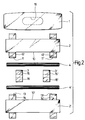
- FIG. 1 we see the articulation device according to the invention which essentially comprises a first link 2 to which is attached a first pin 4 and a second link 2 ' to which is attached a second pin 4 '.
- the first link 2 with its pin 4 faces the second link 2 'with its pin 4'.
- Pins 4 and 4 ' are connected together by means of connecting members 3 and 3 '.
- the figure 1 also shows that the articulation device is completely covered by a cap 1, cut in this figure so that only the parts are visible lateral of said cap. Cap 1 surrounds links 2 and 2 'completely and at least the edges 10 and 10 'of these, which appears better on the cuts Figures 1 and 5.
- Figure 5 shows more particularly that the edges 10 and 10 ′ of the links 2 and 2 'are covered by the cover 1 whatever the angle of rotation of links 2 and 2 '.
- Figures 1, 5 and 9 show that the cap 1 is held in place by an insert 5 which passes through the cap through an opening 19 and just locks between the first and second pins 4 and 4 '.
- FIG. 13 is a top view of a portion of this bracelet, the one that is apparent to the eye.
- caps 1 and links 2 and 2 ' the caps over the links and giving the bracelet a new aesthetic of a beautiful aspect.
- Headdresses and links can be made of the most various, for example stainless steel or gold.
- We could alternate these materials for example using steel for the links 2 and gold for the caps 1 and thus obtain a two-tone bracelet with the most beautiful effect. Synthetic materials could also be used profit, composites containing carbon fibers by example.
- Figure 14 is a bottom view of the bracelet assembled, the one that is against the wrist of the carrier. We see in this figure, in addition to the links 2 and caps 1 already mentioned, the inserts 5 or 6 serving to block the caps 1, these inserts being naturally hidden from view.
- the first link 2 is provided with first and second ears 11 and 11 'arranged substantially at the ends of said link 2. These ears 11 and 11 ′ are pierced holes 12 and 12 'respectively crossed by the first pin 4.
- the second link 2 ' has first and second ears 13 and 13' arranged substantially at the ends of said link 2 '.
- the ears 13 and 13 ' are pierced respectively with holes 14 and 14 'crossed by the second pin 4'.
- Of connecting members interconnect the pins.
- These organs consist of first and second sleeves 3 and 3 'each drilled with a first hole 15 and 15' which are crossed by the first pin 4 and a second hole 16 and 16 'which are crossed by the second pin 4'.
- this insert in two modes of execution, a first mode known as non-removable and a second so-called removable mode.
- the insert is present an oblong shape and passes through a hole 19 made under the cap 1.
- This hole 19 has the same oblong shape as the insert, the latter being fitted with a collar 20 stop under the cover 1 (see for example the Figures 11 and 12).
- insert 5 has an oblong shape whose elongated direction X (see figures 9 and 11) occupies the space left free between the first and second sleeves 3 and 3 '.
- the upper part 21 of insert 5 is elastic, this elasticity being conferred by a groove 30 made in said part upper 21.
- this upper part 21 is provided with first and second elongated cells 22 and 23 which turn on back. As can be seen in FIG.
- these cells 22 and 23 are arranged and sized to fit respectively in the first and second pins 4 and 4 'when the insert 5 is fully inserted under the cover 1.
- This system cannot be dismantled in the sense that it is very difficult to extract insert 5 without damaging it, even if this insert is made of plastic. We will therefore reserve this mode of execution for the part of the bracelet that does not need to be shortened or lengthened.
- the removable insert is illustrated in Figures 4, 8, 12 and 14 and can replace the non-removable insert illustrated in Figures 1, 5 and 9.
- this insert is produced in two parts: a cover 6 of oblong shape fitting into hole 19 of cap 1 with its support flange 20 and two screws 7 and 7 ' crossing this cover 6 in the direction of the arrows B.
- the screws 7 and 7 ' have a cylindrical head 31 and 31 'capable of fit in the bore 32 of the cover 6, the head being provided with a stop collar 33 and a slot 34 likely to receive a screwdriver.
- each screw 7 and 7 ' has the shape of a rectangular parallelepiped which is provided with first and second cells 25 and 26 as is well shown on Figures 8 and 12. These cells 25 and 26 turn the back ( Figure 8).
- the dimensions of the parallelepiped are arranged in such a way that when the screws are located in a determined position, they pass freely between the first and second pins 4 and 4 'then that they are notched by their first and second cells 25 and 26 respectively in the first and second pins 4 and 4 ', when the screws are turned a quarter turn, for example in the direction of the arrows E.
- first and second walls 17 and 18 which face the wall 40 of the link 2, as well as first and second walls 17 'and 18 'which face the wall 40' of the link 2 '.
- these walls 17, 17 'and 18, 18' have a configuration - here two planes forming a obtuse angle - limiting the angle of rotation of the links 2 and 2 '.
- the insert 5 (or the cover 6) also has the function prevent the 3 and 3 'sleeves from moving laterally, these sleeves themselves fixing the cover 1. In this way, a constant day can be guaranteed between cap 1 and links 2 and 2 '.
Description
La présente invention est relative à un dispositif d'articulation entre deux maillons composant un bracelet non extensible, ledit dispositif comportant des première et seconde goupilles attachées, la première à un premier maillon, la seconde à un second maillon faisant face au premier, et des organes de liaison reliant lesdites première et seconde goupilles.The present invention relates to a device of articulation between two links making up a bracelet not extensible, said device comprising first and second pins attached, the first to a first link, the second to a second link facing the first, and connecting members connecting said first and second pins.
On connaít déjà un dispositif d'articulation répondant à la définition générique donnée ci-dessus. Le document CH-A-661 184 décrit des maillons constitués chacun d'une coquille supérieure et d'une coquille inférieure. Des trous borgnes reçoivent des barrettes à ressort au nombre de deux par maillon. L'articulation entre deux maillons se compose donc de deux barrettes reliées ensemble par des brides de liaison qui sont des pièces de tôle découpées et pliées. Ce dispositif présente l'inconvénient de ne pas cacher au regard l'endroit de l'articulation et d'être fragile par l'utilisation d'une tôle qui peut se casser par fatigue.We already know an articulation device meeting the generic definition given above. The document CH-A-661 184 describes constituted links each of a top shell and a shell lower. Blind holes receive bars to comes out two in number per link. The articulation between two links therefore consists of two bars connected together by connecting flanges which are cut and folded sheet metal parts. This device presents the disadvantage of not hiding the place of the joint and to be fragile by the use of a sheet metal which can break by fatigue.
Pour éviter ces inconvénients et pour proposer un système d'articulation de haute qualité technique, le dispositif d'articulation selon l'invention est caractérisé en ce qu'il est entièrement recouvert par une coiffe entourant les maillons, la coiffe couvrant en outre au moins les bords desdits maillons quel que soit l'angle de rotation de ceux-ci, cette coiffe étant maintenue en place par un insert la traversant et venant se cranter entre les première et seconde goupilles.To avoid these drawbacks and to propose a high-quality articulation system, the articulation device according to the invention is characterized in that it is completely covered by a cap surrounding the links, the cap further covering at least the edges of said links whatever the angle of rotation of these, this cap being maintained in placed by an insert crossing it and coming to grip between the first and second pins.
L'invention va être décrite ci-après, à titre d'exemple et en se référant au dessin qui l'illustre dans lequel :
- la figure 1 est une vue de dessus du dispositif d'articulation selon l'invention, vue dans laquelle la partie supérieure de la coiffe a été coupée,
- la figure 2 est une vue de dessus montrant séparément tous les éléments utilisés pour former l'articulation de la figure 1, à l'exception de l'insert,
- les figures 3 et 4 sont des vues de dessus respectivement d'un premier et d'un second mode d'exécution de l'insert propre à maintenir la coiffe en place,
- la figure 5 est une vue de côté du dispositif d'articulation selon l'invention, coupé selon la ligne V-V de la figure 1,
- la figure 6 est une vue de côté montrant séparément les éléments utilisés pour former l'articulation de la figure 5, à l'exception de l'insert,
- les figures 7 et 8 sont des vues de côté respectivement d'un premier et d'un second mode d'exécution de l'insert,
- la figure 9 est une vue de face du dispositif d'articulation selon l'invention, coupé selon la ligne IX-IX de la figure 1,
- la figure 10 est une vue de face montrant séparément les éléments utilisés pour former l'articulation de la figure 9, à l'exception de l'insert,
- les figures 11 et 12 sont des vues de face respectivement d'un premier et d'un second mode d'exécution de l'insert,
- la figure 13 est une vue de dessus d'une portion de bracelet assemblé, et
- la figure 14 est une vue de dessous d'une portion de bracelet assemblé.
- FIG. 1 is a top view of the articulation device according to the invention, a view in which the upper part of the cap has been cut,
- FIG. 2 is a top view showing separately all the elements used to form the joint of FIG. 1, with the exception of the insert,
- FIGS. 3 and 4 are top views respectively of a first and of a second embodiment of the insert suitable for holding the cap in place,
- FIG. 5 is a side view of the articulation device according to the invention, cut along the line VV of FIG. 1,
- FIG. 6 is a side view showing separately the elements used to form the joint of FIG. 5, with the exception of the insert,
- FIGS. 7 and 8 are side views respectively of a first and of a second embodiment of the insert,
- FIG. 9 is a front view of the articulation device according to the invention, cut along the line IX-IX of FIG. 1,
- FIG. 10 is a front view showing separately the elements used to form the joint of FIG. 9, with the exception of the insert,
- FIGS. 11 and 12 are front views respectively of a first and of a second embodiment of the insert,
- FIG. 13 is a top view of a portion of assembled bracelet, and
- Figure 14 is a bottom view of a portion of assembled bracelet.
Si l'on se réfère maintenant à la figure 1, on voit
le dispositif d'articulation selon l'invention qui
comprend essentiellement un premier maillon 2 auquel est
attachée une première goupille 4 et un second maillon 2'
auquel est attachée une seconde goupille 4'. Le premier
maillon 2 avec sa goupille 4 fait face au second maillon
2' avec sa goupille 4'. Les goupilles 4 et 4' sont reliées
ensemble au moyen d'organes de liaison 3 et 3'. La figure
1 montre encore que le dispositif d'articulation est
entièrement recouvert par une coiffe 1, coupée dans cette
figure de sorte que ne sont visibles que les parties
latérales de ladite coiffe. La coiffe 1 entoure
complètement les maillons 2 et 2' et au moins les bords 10
et 10' de ceux-ci, ce qui apparaít mieux sur les coupes
des figures 1 et 5. La figure 5 fait apparaítre plus
particulièrement que les bords 10 et 10' des maillons 2 et
2' sont recouverts par la coiffe 1 quel que soit l'angle
de rotation des maillons 2 et 2'. Enfin les figures 1, 5
et 9 montrent que la coiffe 1 est maintenue en place par
un insert 5 qui traverse la coiffe par une ouverture 19 et
vient se cranter entre les première et seconde goupilles 4
et 4'.If we now refer to Figure 1, we see
the articulation device according to the invention which
essentially comprises a
Le dispositif d'articulation qui vient d'être décrit
dans sa généralité va se répéter de manière semblable pour
toutes les autres articulations du bracelet pour donner
l'aspect fini du bracelet montré aux figures 13 et 14. La
figure 13 est une vue de dessus d'une portion de ce
bracelet, celle qui est apparente au regard. On voit une
succession régulière de coiffes 1 et de maillons 2 et 2',
les coiffes surmontant les maillons et conférant au
bracelet une esthétique nouvelle d'un bel aspect. Coiffes
et maillons peuvent être réalisés en matériaux les plus
divers, par exemple de l'acier inoxydable ou de l'or. On
pourrait alterner ces matériaux, par exemple en utilisant
de l'acier pour les maillons 2 et de l'or pour les coiffes
1 et obtenir ainsi un bracelet bicolore du plus bel effet.
Des matières synthétiques pourraient aussi être mises à
profit, des composites contenant des fibres de carbone par
exemple. La figure 14 est une vue de dessous du bracelet
assemblé, celle qui se trouve contre le poignet du
porteur. On voit dans cette figure, en plus des maillons 2
et des coiffes 1 déjà cités, les inserts 5 ou 6 servant à
bloquer les coiffes 1, ces inserts étant naturellement
cachés au regard.The articulation device which has just been described
in general will repeat itself in a similar way for
all the other joints of the bracelet to give
the finished appearance of the bracelet shown in Figures 13 and 14. The
Figure 13 is a top view of a portion of this
bracelet, the one that is apparent to the eye. We see a
regular succession of
On va maintenant décrire plus en détail un mode de réalisation préféré du dispositif d'articulation selon l'invention. On se servira pour cela, non seulement des figures 1, 5 et 9 déjà citées, mais encore des figures 2, 6 et 10 qui présentent respectivement, des vues de dessus, de côté et de face des éléments utilisés pour former le dispositif d'articulation.We will now describe in more detail a mode of preferred embodiment of the articulation device according to the invention. We will use for this, not only the Figures 1, 5 and 9 already cited, but also Figures 2, 6 and 10 which respectively show top views, side and front of the elements used to form the articulation device.
Comme cela est bien apparent aux figures 1 et 2, le
premier maillon 2 est pourvu de première et seconde
oreilles 11 et 11' disposées sensiblement aux extrémités
dudit maillon 2. Ces oreilles 11 et 11' sont percées
respectivement de trous 12 et 12' traversés par la
première goupille 4. De façon analogue, le second maillon
2' est pourvu de première et seconde oreilles 13 et 13'
disposées sensiblement aux extrémités dudit maillon 2'.
Les oreilles 13 et 13' sont percées respectivement de
trous 14 et 14' traversés par la seconde goupille 4'. Des
organes de liaison relient entre elles les goupilles. Ces
organes consistent en des premier et second manchons 3 et
3' percés chacun d'un premier trou 15 et 15' qui sont
traversés par la première goupille 4 et d'un second trou
16 et 16' qui sont traversés par la seconde goupille 4'.
Ces manchons 3 et 3' sont situés entre les premières et
secondes oreilles référencées respectivement 11, 13 et
11', 13' et prennent appui contre elles. Dans l'espace
laissé libre entre les manchons 3 et 3' vient se loger
l'insert dont il a déjà été question, cet insert venant se
cranter entre les premier et second manchons 3 et 3' pour
fixer la coiffe 1 sur le dispositif d'articulation, comme
cela va être exposé ci-dessous.As is apparent from Figures 1 and 2, the
Il est prévu de proposer cet insert selon deux modes
d'exécution, un premier mode dit indémontable et un second
mode dit démontable. Dans les deux cas l'insert présente
une forme oblongue et traverse un trou 19 pratiqué sous la
coiffe 1. Ce trou 19 présente la même forme oblongue que
l'insert, ce dernier étant équipé d'une collerette 20
d'arrêt s'appuyant sous la coiffe 1 (voir par exemple les
figures 11 et 12). Ces deux modes d'exécution vont être
décrits maintenant dans le détail.It is planned to offer this insert in two modes
of execution, a first mode known as non-removable and a second
so-called removable mode. In both cases the insert is present
an oblong shape and passes through a
L'insert indémontable est illustré aux figures 1, 3,
5, 7, 9, 11 et 14. Il porte la référence 5 et est fait
d'une seule pièce. Comme mentionné ci-dessus, l'insert 5
présente une forme oblongue dont la direction allongée X
(voir figures 9 et 11) occupe l'espace laissé libre entre
les premier et second manchons 3 et 3'. Comme le montre
bien les figures 5 et 7, la partie supérieure 21 de
l'insert 5 est élastique, cette élasticité lui étant
conférée par une saignée 30 pratiquée dans ladite partie
supérieure 21. Comme le montrent bien les figures 5 et 7,
cette partie supérieure 21 est munie de première et
seconde alvéoles allongées 22 et 23 qui se tournent le
dos. Comme on peut le voir en figure 5, ces alvéoles 22 et
23 sont arrangées et dimensionnées pour venir se cranter
respectivement dans les première et seconde goupilles 4 et
4' quand l'insert 5 est introduit à fond sous la coiffe 1.
Ce système est indémontable en ce sens qu'il est très
difficile d'extraire l'insert 5 sans le détériorer, même
si cet insert est réalisé en matière plastique. On
réservera donc ce mode d'exécution pour la partie du
bracelet qui n'a pas besoin d'être raccourcie ou allongée.The non-removable insert is illustrated in Figures 1, 3,
5, 7, 9, 11 and 14. It bears the
L'insert démontable est illustré aux figures 4, 8, 12
et 14 et peut remplacer l'insert indémontable illustré aux
figures 1, 5 et 9. Comme le montrent les figures 4, 8 et
12, cet insert est réalisé en deux parties : un capot 6 de
forme oblongue s'ajustant dans le trou 19 de la coiffe 1
avec sa collerette d'appui 20 et deux vis 7 et 7'
traversant ce capot 6 dans le sens des flèches B. Comme on
le voit bien sur les figures 4, 8 et 12, les vis 7 et 7'
présentent une tête cylindrique 31 et 31' susceptible de
s'ajuster dans l'alésage 32 du capot 6, la tête étant
munie d'une collerette d'arrêt 33 et d'une fente 34
susceptible de recevoir un tournevis. La partie supérieure
24 de chaque vis 7 et 7' présente la forme d'un
parallélépipède rectangle qui est pourvu de première et
seconde alvéoles 25 et 26 comme cela est bien montré sur
les figures 8 et 12. Ces alvéoles 25 et 26 se tournent le
dos (figure 8). Les dimensions du parallélépipède sont
arrangées de telle façon que, lorsque les vis se trouvent
dans une position déterminée, elles passent librement
entre les première et seconde goupilles 4 et 4' alors
qu'elles se crantent par leurs première et seconde
alvéoles 25 et 26 respectivement dans les première et
seconde goupilles 4 et 4', quand les vis sont tournées
d'un quart de tour, par exemple dans le sens des flèches
E.The removable insert is illustrated in Figures 4, 8, 12
and 14 and can replace the non-removable insert illustrated in
Figures 1, 5 and 9. As shown in Figures 4, 8 and
12, this insert is produced in two parts: a
Si l'on se reporte maintenant plus particulièrement
au dispositif présenté en coupe à la figure 5 et aux
éléments composant ce dispositif présentés en figure 6, on
s'aperçoit que le manchon 3' (de même que le manchon 3 non
représenté sur ces figures) est pourvu de première et
seconde parois 17 et 18 qui font face à la paroi 40 du
maillon 2, ainsi que de première et seconde parois 17' et
18' qui font face à la paroi 40' du maillon 2'. Comme on
le voit bien en figure 5, ces parois 17, 17' et 18, 18'
présentent une configuration - ici deux plans formant un
angle obtus - limitant l'angle de rotation des maillons 2
et 2'. Ainsi on a représenté en figure 5 un maillon 2 en
position extrême vers le haut, la paroi 40 du maillon 2
venant s'appuyer contre la paroi 17 du manchon 3'. A
partir de cette position, le maillon 2 ne peut se mouvoir
que vers le bas dans le sens de la flèche F. Cette figure
montre de façon analogue un maillon 2' en position extrême
vers le bas, la paroi 40' du maillon 2' venant s'appuyer
contre la paroi 18' du manchon 3'. A partir de cette
position, le maillon 2' ne peut se mouvoir que vers le
haut, dans le sens de la flèche G. La disposition qui
vient d'être décrite fait comprendre que l'angle de
rotation des maillons 2 et 2' est donné par les manchons 3
et 3' de sorte que l'effort d'arrêt se porte sur les
maillons 2 et 2' et nullement sur la coiffe 1 qui n'est
donc pas sollicitée mécaniquement.If we now refer more particularly
to the device presented in section in FIG. 5 and to
components of this device presented in Figure 6, we
realizes that the sleeve 3 '(as well as the
Si l'on se reporte encore une fois aux figures 5 et
6, on remarque que les trous 12' et 14' percés dans les
oreilles 11' et 13' des maillons 2 et 2' sont oblongs. Il
en va de même pour les trous 12 et 14 percés dans les
oreilles 11 et 13 non représentées ici. Les figures
montrent aussi que la dimension allongée de la forme
oblongue des trous est dirigée dans le sens de l'épaisseur
des maillons 2 et 2'. Cette forme est importante, car on
comprendra qu'en plus de la rotation du maillon autour de
la goupille à laquelle il est attaché, le maillon est
susceptible de se mouvoir verticalement, dans le sens de
l'épaisseur du bracelet, ce qui réduit considérablement le
jour entre les maillons et la coiffe qui les recouvre.
Cela est illustré par la figure 5. On voit que le maillon
2 de gauche présente par rapport à la coiffe des jours à
peu près égaux sur le haut et sur le bas du maillon. La
goupille 4 est alors en contact avec le haut du trou
oblong 12'. En ce qui concerne le maillon 2' de droite, sa
partie basse touche la coiffe, alors que sa partie haute
présente un jour par rapport à la coiffe qui est à peu
près le double de ce qui est montré à gauche de la figure.
La goupille 4' est alors en contact avec le bas du trou
oblong 14'. En résumé cette disposition permet un angle de
rotation maximum des maillons pour un jour minimum entre
maillons et coiffe.If we refer again to Figures 5 and
6, we note that the holes 12 'and 14' drilled in the
ears 11 'and 13' of the
On va donner pour terminer quelques indications
concernant le montage du dispositif d'articulation. On
peut alors se référer à la figure 2. On fournit des
premier et second maillons 2 et 2', des première et
seconde goupilles 4 et 4', des premier et second manchons
3 et 3' et une coiffe 1. On introduit, par la gauche de la
figure la goupille 4 dans l'oreille 11 jusqu'à ce qu'elle
émerge assez pour y glisser les manchons 3 et 3' par leurs
trous 15 et 15'. On termine l'introduction de la goupille
4 dans l'oreille 11' à travers le trou 12' de cette
oreille. On approche de ce prémontage le maillon 2' pour
aligner les trous 13 et 13' de ce maillon 2' avec les
trous 16 et 16' des manchons 3 et 3'. On introduit la
goupille 4' dans les trous ainsi alignés. On glisse sur
l'assemblage ainsi réalisé la coiffe 1 jusqu'à ce que
l'ouverture 19 de cette coiffe soit centré sur les
goupilles 4 et 4'. Les goupilles sont alors prisonnières
de la coiffe 1. Par l'ouverture 19 on pousse les manchons
l'un à droite, l'autre à gauche pour qu'ils viennent en
appui respectivement sur les oreilles des maillons (voir
figures 1 et 9). On introduit l'insert 5 (figures 3, 7 et
11) par l'ouverture 19, jusqu'à ce que ses alvéoles 22 et
23 viennent se cranter sur les goupilles 4 et 4'. Le
montage est alors terminé.We will give to finish some indications
concerning the assembly of the articulation device. We
can then refer to Figure 2. We provide
first and
Si l'on choisit l'autre type d'exécution d'insert,
celui montré aux figures 4, 8 et 12, on commence par
introduire à fond le capot 6 dans l'ouverture 19. On
introduit les vis 7 et 7' dans les trous 32 du capot 6 de
manière à ce que le petit côté A de ces vis passe entre
les goupilles 4 et 4'. Au moyen d'un tournevis on tourne
ces vis d'un quart de tour, cette action ayant pour effet
de cranter les alvéoles 25 et 26 desdites vis dans les
goupilles 4 et 4'. On a déjà dit que cette forme
d'exécution est démontable. Il suffit pour cela de tourner
les vis 7 et 7' d'un nouveau quart de tour, ce qui a pour
effet de décranter les alvéoles 25 et 26 des goupilles 4
et 4', ce qui permet de retirer les vis 7 et 7', puis le
capot 6.If we choose the other type of insert execution,
the one shown in figures 4, 8 and 12, we start with
fully insert the
On signalera encore, voir par exemple la figure 9,
que l'insert 5 (ou le capot 6) a aussi pour fonction
d'empêcher les manchons 3 et 3' de se déplacer
latéralement, ces manchons eux-mêmes fixant la coiffe 1.
De cette manière, un jour constant peut être garanti entre
la coiffe 1 et les maillons 2 et 2'.We will also indicate, see for example Figure 9,
that the insert 5 (or the cover 6) also has the function
prevent the 3 and 3 'sleeves from moving
laterally, these sleeves themselves fixing the
Claims (8)
- Articulation device connecting links forming a non-extending bracelet, said device including first (4) and second (4') pins which are attached, the first to a first link (2), the second to a second link (2') facing the first, and connecting elements (3, 3') connecting said first and second pins, characterised in that said device is entirely covered by a cover (1) surrounding the links, the cover further covering at least the edges (10, 10') of said links whatever the angle of rotation thereof, said cover being held in place by an insert (5; 6, 7, 7') which passes through it and is caught between said first and second pins.
- Device according to claim 1, characterised in that the first pin (4) passes through first (11) and second (11') lugs pierced with holes (12, 12') and arranged substantially at the ends of the first link (2), in that the second pin (4') passes through first (13) and second (13') lugs pierced with holes (14, 14') and arranged substantially at the ends of the second link (2'), in that the connecting elements consist of first (3) and second (3') sleeves each pierced with a first hole (15, 15') for the first pin (4) to pass through and a second hole (16, 16') for the second pin (4') to pass through, said first (3) and second (3') sleeves being situated between the first (11, 13) and second (11', 13') lugs and abutting respectively against them, and in that the insert (5; 6, 7, 7') is caught between said first (4) and second (4') pins in the free space between said first (3) and second (3') sleeves.
- Device according to claim 2, characterised in that the walls (17, 17'; 18, 18') of the sleeves facing the links (2, 2') have a configuration which limits the angle of rotation of said links, these links abutting against said sleeves in their end positions.
- Device according to claim 2, characterised in that the holes (12, 12'; 14, 14') made in the lugs (11, 11'; 13, 13') of the links (2, 2') are oblong, the elongated dimension being directed in the direction of the thickness of the links.
- Device according to claim 2, characterised in that the insert (5; 6) has an oblong shape and in that it passes through a hole (19) made under the cover (1), this hole having the same oblong shape as the insert, the latter having a stop? flange (20) abutting under said cover.
- Device according to claim 5, characterised in that the insert is made in a single part (5) the elongated dimension (X) of which occupies the space left free between the first (3) and second (3') sleeves and in that the top part (21) of said insert is elastic, said top part being provided with first (22) and second (23) elongated bores arranged back-to-back, these bores being arranged and sized to be caught respectively in the first (4) and second (4') pins.
- Device according to claim 5, characterised in that the insert is made of a cap (6) of oblong shape and two screws (7, 7') passing through said cap, the top part (24) of each of these screws having the shape of a rectangular parallelepiped provided with first (25) and second (26) back-to-back bores, this parallelepiped being arranged and sized so as to pass between the first (4) and second (4') pins when the screws are arranged in a determined position and to be caught by first (25) and second (26) bores respectively in the first (4) and second (4') pins when the screws are turned by a quarter of a turn.
- Device according to claim 1, characterised in that the cover (1) is obtained by cutting up a drawn tube the inner profile of which is substantially equal to the outer profile of the links (2, 2').
Applications Claiming Priority (2)
| Application Number | Priority Date | Filing Date | Title |
|---|---|---|---|
| FR9504812A FR2733126B1 (en) | 1995-04-21 | 1995-04-21 | ARTICULATION DEVICE FOR CONNECTING BETWEEN THE LINKS OF A BRACELET |
| FR9504812 | 1995-04-21 |
Publications (2)
| Publication Number | Publication Date |
|---|---|
| EP0738480A1 EP0738480A1 (en) | 1996-10-23 |
| EP0738480B1 true EP0738480B1 (en) | 2000-07-26 |
Family
ID=9478348
Family Applications (1)
| Application Number | Title | Priority Date | Filing Date |
|---|---|---|---|
| EP19960105860 Expired - Lifetime EP0738480B1 (en) | 1995-04-21 | 1996-04-15 | Articulation device for connecting bracelet links |
Country Status (3)
| Country | Link |
|---|---|
| EP (1) | EP0738480B1 (en) |
| DE (1) | DE69609444T2 (en) |
| FR (1) | FR2733126B1 (en) |
Families Citing this family (3)
| Publication number | Priority date | Publication date | Assignee | Title |
|---|---|---|---|---|
| EP1186252A1 (en) | 2000-09-09 | 2002-03-13 | Conseils et Manufactures VLG SA | Bracelet with links |
| ATE366058T1 (en) * | 2005-06-06 | 2007-07-15 | Swatch Group Man Serv Ag | NON-EXPANDABLE LINK BRACELET |
| EP1977658B1 (en) | 2007-04-05 | 2016-08-10 | Glashütter Uhrenbetrieb GmbH | Bracelet made up of articulated links |
Family Cites Families (5)
| Publication number | Priority date | Publication date | Assignee | Title |
|---|---|---|---|---|
| US2537449A (en) * | 1948-07-06 | 1951-01-09 | Emil E Evenson | Ring |
| CH661184A5 (en) * | 1984-12-19 | 1987-07-15 | Finger H Fa | Bracelet, particularly a watch bracelet, and method for manufacturing this bracelet |
| US4969241A (en) * | 1990-02-28 | 1990-11-13 | Griffin Joetta R | Button cover assembly |
| FR2685614B1 (en) * | 1991-12-31 | 1994-03-04 | Rado Sa Montres | LINK STRAP, ESPECIALLY FOR A WATCH. |
| CH689105A5 (en) * | 1992-01-21 | 1998-10-15 | Complications Sa | Bracelet, including watchband. |
-
1995
- 1995-04-21 FR FR9504812A patent/FR2733126B1/en not_active Expired - Fee Related
-
1996
- 1996-04-15 DE DE1996609444 patent/DE69609444T2/en not_active Expired - Fee Related
- 1996-04-15 EP EP19960105860 patent/EP0738480B1/en not_active Expired - Lifetime
Also Published As
| Publication number | Publication date |
|---|---|
| FR2733126B1 (en) | 1997-06-20 |
| FR2733126A1 (en) | 1996-10-25 |
| DE69609444D1 (en) | 2000-08-31 |
| EP0738480A1 (en) | 1996-10-23 |
| DE69609444T2 (en) | 2001-03-08 |
Similar Documents
| Publication | Publication Date | Title |
|---|---|---|
| EP1005279B1 (en) | Ornamental chain consisting of successive elements each having a general spherical shape | |
| EP2082282B1 (en) | Elastic hinge member having a large amplitude for spectacles rims | |
| FR2704785A1 (en) | Improvements to tools for the realization of assembly points of sheets by cold creep. | |
| EP0466656A1 (en) | Bracelet fastener | |
| EP1136010B1 (en) | Articulated bracelet, particularly for watches | |
| EP0738480B1 (en) | Articulation device for connecting bracelet links | |
| WO2015185831A1 (en) | Spectacle frame having clipped-together removable temples made of metal strips | |
| CA2716470A1 (en) | Eyeglass frame | |
| FR2741459A1 (en) | Spring=loaded spectacle hinge | |
| FR2619292A1 (en) | Bracelet clasp | |
| FR2761720A1 (en) | LOCKING FITTING FOR SLIDING OPENING | |
| EP0234406B1 (en) | Non-expanding bracelet with visible joints | |
| WO1999004306A1 (en) | Elastic hinge for flat spectacle bow | |
| FR2705606A1 (en) | Device for the articulated joining together of a handle and a blade in particular | |
| EP2525247B1 (en) | Spectacle frame with joint | |
| FR2880138A1 (en) | Spectacle frame`s temple structures and nasal support unit fixing device for assembling spectacle frame, has sleeves whose bodies are of oblong shape, and protrusions presenting oblong shape so that they are not rotated in cavity | |
| FR2814138A1 (en) | READY-TO-FIT FOR FASTENING A CANISTER | |
| FR2718254A1 (en) | Lens retainer for spectacle frame | |
| FR2748128A1 (en) | Fixing for rigid connection between spectacle lens and frame | |
| FR2879415A1 (en) | Hair pin for maintaining mass of hair, has lock arm with body whose length is lower than that of hairpin body and fixed and free ends directed towards gripping and insertion ends of hair pin body, and engagement space engaging mass of hair | |
| WO2004040356A1 (en) | Shield for glasses and components for making such a shield | |
| FR2849510A1 (en) | Spectacle frame, has fixation unit constituted by adjustable slide including zone penetrating into blind hole, where penetration zone is in polygonal section and includes anchoring point in adhesive | |
| FR2558199A1 (en) | SCAFFOLDING ELEMENT, IN PARTICULAR CONSOLE, WITH TIP FOR ENGAGING ANOTHER ELEMENT AND DRILLING FOR IMPLANTING A PIN THROUGH THE SAME | |
| FR2548722A1 (en) | Butt and strap hinge | |
| FR2521660A1 (en) | METHOD FOR PRODUCING A BEARING LOCATED BETWEEN TWO REMOTE PARTITIONS AND DEVICE FOR IMPLEMENTING IT |
Legal Events
| Date | Code | Title | Description |
|---|---|---|---|
| PUAI | Public reference made under article 153(3) epc to a published international application that has entered the european phase |
Free format text: ORIGINAL CODE: 0009012 |
|
| AK | Designated contracting states |
Kind code of ref document: A1 Designated state(s): CH DE FR GB IT LI |
|
| 17P | Request for examination filed |
Effective date: 19970423 |
|
| GRAG | Despatch of communication of intention to grant |
Free format text: ORIGINAL CODE: EPIDOS AGRA |
|
| 17Q | First examination report despatched |
Effective date: 19990429 |
|
| GRAG | Despatch of communication of intention to grant |
Free format text: ORIGINAL CODE: EPIDOS AGRA |
|
| GRAH | Despatch of communication of intention to grant a patent |
Free format text: ORIGINAL CODE: EPIDOS IGRA |
|
| GRAH | Despatch of communication of intention to grant a patent |
Free format text: ORIGINAL CODE: EPIDOS IGRA |
|
| GRAA | (expected) grant |
Free format text: ORIGINAL CODE: 0009210 |
|
| AK | Designated contracting states |
Kind code of ref document: B1 Designated state(s): CH DE FR GB IT LI |
|
| REG | Reference to a national code |
Ref country code: CH Ref legal event code: EP |
|
| REF | Corresponds to: |
Ref document number: 69609444 Country of ref document: DE Date of ref document: 20000831 |
|
| ITF | It: translation for a ep patent filed |
Owner name: PROROGA CONCESSA IN DATA: 14.03.2001;BOTTI & FERRA |
|
| GBT | Gb: translation of ep patent filed (gb section 77(6)(a)/1977) |
Effective date: 20001024 |
|
| PLBE | No opposition filed within time limit |
Free format text: ORIGINAL CODE: 0009261 |
|
| STAA | Information on the status of an ep patent application or granted ep patent |
Free format text: STATUS: NO OPPOSITION FILED WITHIN TIME LIMIT |
|
| 26N | No opposition filed | ||
| REG | Reference to a national code |
Ref country code: GB Ref legal event code: IF02 |
|
| PGFP | Annual fee paid to national office [announced via postgrant information from national office to epo] |
Ref country code: GB Payment date: 20020327 Year of fee payment: 7 |
|
| PGFP | Annual fee paid to national office [announced via postgrant information from national office to epo] |
Ref country code: FR Payment date: 20020426 Year of fee payment: 7 |
|
| PGFP | Annual fee paid to national office [announced via postgrant information from national office to epo] |
Ref country code: DE Payment date: 20030409 Year of fee payment: 8 |
|
| PG25 | Lapsed in a contracting state [announced via postgrant information from national office to epo] |
Ref country code: GB Free format text: LAPSE BECAUSE OF NON-PAYMENT OF DUE FEES Effective date: 20030415 |
|
| GBPC | Gb: european patent ceased through non-payment of renewal fee |
Effective date: 20030415 |
|
| PG25 | Lapsed in a contracting state [announced via postgrant information from national office to epo] |
Ref country code: FR Free format text: LAPSE BECAUSE OF NON-PAYMENT OF DUE FEES Effective date: 20031231 |
|
| REG | Reference to a national code |
Ref country code: FR Ref legal event code: ST |
|
| PG25 | Lapsed in a contracting state [announced via postgrant information from national office to epo] |
Ref country code: DE Free format text: LAPSE BECAUSE OF NON-PAYMENT OF DUE FEES Effective date: 20041103 |
|
| REG | Reference to a national code |
Ref country code: CH Ref legal event code: PL |
|
| PGFP | Annual fee paid to national office [announced via postgrant information from national office to epo] |
Ref country code: CH Payment date: 20050113 Year of fee payment: 9 |
|
| REG | Reference to a national code |
Ref country code: CH Ref legal event code: AEN Free format text: LE BREVET A ETE REACTIVE SELON LA DEMANDE DE POURSUITE DE LA PROCEDURE DU 13.01.2005. |
|
| PG25 | Lapsed in a contracting state [announced via postgrant information from national office to epo] |
Ref country code: IT Free format text: LAPSE BECAUSE OF NON-PAYMENT OF DUE FEES Effective date: 20050415 |
|
| REG | Reference to a national code |
Ref country code: CH Ref legal event code: PL |
|
| REG | Reference to a national code |
Ref country code: CH Ref legal event code: PL Ref country code: CH Ref legal event code: PK Free format text: LA POURSUITE DE LA PROCEDURE APRES LE NON-PAIEMENT DE LA 9E ANNUITE A ETE ENREGISTREE PAR ERREUR. LE BREVET A ETE DEJA RADIE LE 30.04.2003 POUR LE NON |