EP2525247B1 - Spectacle frame with joint - Google Patents
Spectacle frame with joint Download PDFInfo
- Publication number
- EP2525247B1 EP2525247B1 EP12168311.4A EP12168311A EP2525247B1 EP 2525247 B1 EP2525247 B1 EP 2525247B1 EP 12168311 A EP12168311 A EP 12168311A EP 2525247 B1 EP2525247 B1 EP 2525247B1
- Authority
- EP
- European Patent Office
- Prior art keywords
- branch
- pin
- frame according
- joint body
- open
- Prior art date
- Legal status (The legal status is an assumption and is not a legal conclusion. Google has not performed a legal analysis and makes no representation as to the accuracy of the status listed.)
- Active
Links
- 239000002184 metal Substances 0.000 claims description 16
- 229910052751 metal Inorganic materials 0.000 claims description 16
- 239000000463 material Substances 0.000 claims description 6
- 239000004033 plastic Substances 0.000 claims description 4
- 230000014759 maintenance of location Effects 0.000 claims description 3
- 229910000831 Steel Inorganic materials 0.000 claims 1
- RTAQQCXQSZGOHL-UHFFFAOYSA-N Titanium Chemical compound [Ti] RTAQQCXQSZGOHL-UHFFFAOYSA-N 0.000 claims 1
- 239000010959 steel Substances 0.000 claims 1
- 239000010936 titanium Substances 0.000 claims 1
- 229910052719 titanium Inorganic materials 0.000 claims 1
- 239000011521 glass Substances 0.000 description 9
- 238000003466 welding Methods 0.000 description 3
- 238000004519 manufacturing process Methods 0.000 description 2
- 229910001040 Beta-titanium Inorganic materials 0.000 description 1
- 239000004952 Polyamide Substances 0.000 description 1
- 238000005219 brazing Methods 0.000 description 1
- 210000004027 cell Anatomy 0.000 description 1
- 239000013536 elastomeric material Substances 0.000 description 1
- 238000002347 injection Methods 0.000 description 1
- 239000007924 injection Substances 0.000 description 1
- 238000003754 machining Methods 0.000 description 1
- 229920002647 polyamide Polymers 0.000 description 1
- 230000001681 protective effect Effects 0.000 description 1
- 229910001220 stainless steel Inorganic materials 0.000 description 1
- 239000010935 stainless steel Substances 0.000 description 1
- 239000012815 thermoplastic material Substances 0.000 description 1
- 239000002023 wood Substances 0.000 description 1
Images


Classifications
-
- G—PHYSICS
- G02—OPTICS
- G02C—SPECTACLES; SUNGLASSES OR GOGGLES INSOFAR AS THEY HAVE THE SAME FEATURES AS SPECTACLES; CONTACT LENSES
- G02C5/00—Constructions of non-optical parts
- G02C5/22—Hinges
- G02C5/2209—Pivot bearings and hinge bolts other than screws
-
- G—PHYSICS
- G02—OPTICS
- G02C—SPECTACLES; SUNGLASSES OR GOGGLES INSOFAR AS THEY HAVE THE SAME FEATURES AS SPECTACLES; CONTACT LENSES
- G02C5/00—Constructions of non-optical parts
- G02C5/008—Spectacles frames characterized by their material, material structure and material properties
-
- G—PHYSICS
- G02—OPTICS
- G02C—SPECTACLES; SUNGLASSES OR GOGGLES INSOFAR AS THEY HAVE THE SAME FEATURES AS SPECTACLES; CONTACT LENSES
- G02C2200/00—Generic mechanical aspects applicable to one or more of the groups G02C1/00 - G02C5/00 and G02C9/00 - G02C13/00 and their subgroups
- G02C2200/04—Junctions between frame elements having a click function
-
- G—PHYSICS
- G02—OPTICS
- G02C—SPECTACLES; SUNGLASSES OR GOGGLES INSOFAR AS THEY HAVE THE SAME FEATURES AS SPECTACLES; CONTACT LENSES
- G02C2200/00—Generic mechanical aspects applicable to one or more of the groups G02C1/00 - G02C5/00 and G02C9/00 - G02C13/00 and their subgroups
- G02C2200/10—Frame or frame portions made from wire
Definitions
- the present invention relates to a spectacle frame, such as corrective glasses and protective glasses, for example sun glasses.
- a pair of glasses generally includes two lenses, commonly called lenses, housed in a front part of the frame to which temples are connected by hinges.
- the front part generally includes a central bridge connecting the two lenses to each other and side pins each connecting a hinge to one of the lenses.
- the front part includes rims each surrounding a lens.
- the straps are connected together by the trigger guard and are each connected to a hinge of a branch by a tenon.
- Extremely thin and light frames are also known in which the front part consists of a bridge fixed directly to the lenses and tenons each fixed directly to one of the lenses.
- Some frames are made from twisted metal pieces.
- hinges in thin frames is very delicate due to the little material which is present at the end of the tenons and at the end of the branches and which prevents the machining of all or part of the hinge at these ends.
- the hinges are therefore generally attached to the ends of the tenons and branches by welding or brazing.
- the small size of the parts makes the hinge and welding operation expensive.
- the welding operation is also delicate and may require additional finishing treatment to give the frame its final appearance.
- the metal parts are wires, which makes the making the hinges even more delicate and expensive.
- the document WO 98/19203 A1 discloses a spectacle frame comprising a tenon and a branch connected by a hinge body defining a pivot axis.
- the tenon is made in an almost closed loop and the branch in an open loop and the joint body has three annular grooves coaxial with the pivot axis.
- the loop of the branch is positioned between the loop of the tenon and the joint body is pressed along the pivot axis until each of the loops engages in a groove of the body. joint.
- WO 99/14628 A1 discloses a spectacle frame comprising a tenon with an open loop elastically clipped into a groove of a joint body. A branch is clipped onto a portion of the tenon loop by means of a stop.
- An aim of the invention is to provide a means for simplifying the production of hinges for spectacle frames based on twisted metal parts, such as wire frames.
- a spectacle frame comprising at least one tenon and one branch made from at least one twisted metal part and connected by a hinge comprising an articulation body defining an axis of pivoting.
- the articulation body comprises at least two annular grooves coaxial with the pivot axis and the tenon and the branch each have a portion shaped like an open loop to be elastically engaged in one of the grooves in a direction transverse to the pivot axis so as to ensure elastic retention of the tenon and the branch on the joint body and to allow pivoting of the branch relative to the tenon.
- the tenon and the branch are clipped onto the joint body which connects them to each other.
- the hinge is then particularly simple.
- the lateral engagement of the open loops on the joint body makes it possible to have relatively deep grooves, which improves the guidance of the loops relative to the joint body.
- the lateral engagement also allows better control of the clearances between the open loops and the joint body, and therefore also of the friction between the open loops and the joint body.
- At least one of the open loops has a free end curved to abut against the other open loop and limit an amplitude of pivoting of the branch relative to the tenon.
- the maximum amplitude of pivoting is thus defined by the end forming a stop in a single piece with the branch or the tenon.
- the curved free end belongs to the tenon.
- This embodiment is particularly simple.
- the joint body is made of one-piece plastic material.
- the body can then be produced by injection of thermoplastic material into a mold, which is particularly simple and economical.
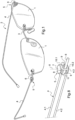
- the pair of glasses comprises two lenses 1 provided with a frame generally designated 2.
- the frame 2 includes a bridge 3 connecting the lenses 1 to each other and generally carrying support pads on the wings of the nose.
- the frame 2 also includes branches 4 each connected by a hinge generally designated at 5 to a tenon 6 fixed to one of the lenses 1.
- the trigger guard 3, the branches 4 and the tenons 6 are made from twisted metal wires as in the figures 1 to 4 , 8 And 9 to 15 representing the first, third and fourth embodiments, and from flat metal strips twisted as in the figures 5 to 7 representing the second embodiment.
- the metal used here is ⁇ titanium.
- the hinge 5 comprises a hinge body 7 defining a pivot axis 8.
- the hinge body 7 comprises annular grooves 9 coaxial with the pivot axis 8.
- the hinge body 7 is made of one-piece plastic material, for example polyamide.
- the grooves 9 are two in number and have a semi-circular cross section.
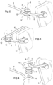
- the branch 4 and the tenon 6 each have one end shaped like an open loop 10, 11 respectively.
- Each of the open loops 10, 11 is elastically engaged in one of the grooves 9 in a direction transverse to the pivot axis 8 so as to ensure elastic retention of the tenon 6 and the branch 4 on the articulation body 5 and to allow pivoting of the branch 4 relative to the tenon 6.
- the opening of the open loops 10, 11 has a width less than the diameter at the bottom of the grooves 9 of the joint body 5 and the open loops 10, 11 have an internal diameter slightly less than the diameter at the bottom of the grooves 9 of the joint body 5 and much less than the external diameter of the joint body 5.
- the open loops 10, 11 have an internal diameter slightly greater than the diameter at the bottom of the grooves 9 of the joint body 5.
- the open loop 11 has a curved free end 12 to abut against the other open loop 10 and more particularly against the connection zone of a substantially rectilinear portion of the branch 4 to the open loop 10 (see the figure 2 ).
- This abutment makes it possible to limit an amplitude of pivoting of the branch 4 relative to the tenon 6.
- the plane of the open loop 10 is offset relative to a plane containing the branches 4 in such a way that each branch 4 unfolds is located in the extension of the tenon 6 to which it is connected.
- the grooves 9 of the joint body 5 are two in number and have a rectangular cross section.
- the branches 4 and the tenons 6 have the same geometry as in the previous embodiment but are made up of twisted flat metal blades, of rectangular section, instead of wires of circular section.
- each branch 4 is double branches each made by means of a metal rod twisted in such a way that each branch 4 comprises two longitudinal sections 4.1, 4.2 having ends shaped like loops open 10.1, 10.2 and connected to each other by a transverse section 4.3 and opposite ends joined by a sleeve, not visible in the figure, for contact with the wearer's head.
- the tenon 6 has a non-visible end connecting to the lens and an opposite end shaped like an open loop 11.
- the joint body 5 has three grooves 9, namely a central groove for receiving the loop 11 and two external grooves for each receiving a loop 10.
- transverse section 4.3 of the branch 4 in the open position abuts against the tenon 6 to limit the opening of said branch.
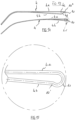
- the metal wire constituting the twisted metal part forming each branch 4 comprises two sections 4a, 4b.
- Sections 4a, 4b extend on either side of a portion intermediate forming the open loop 10.
- the sections 4a, 4b are adjacent to each other and extend facing each other, defining between them a passage 4c allowing the introduction between the sections 4a, 4b of the joint body 5 parallel to its central axis.
- the passage 4c is arranged in such a way that the open loop 10 opens laterally in the passage 4c through an opening of width less than the diameter at the bottom of the grooves 9 of the joint body 5.
- Sections 4a and 4b diverge from each other from the ear end of the branch towards open loop 10.
- Section 4b extends under section 4a, which is rectilinear, and connects to the open loop 10 by a connection portion 4d substantially in the shape of an S. This makes it possible to offer a passage 4c of large dimensions allowing easy introduction of the joint body 5.
- the connection portion 4d is connected to the open loop 10 by forming a angle 10' which is oriented towards the opposite end of the section 4a to define with the latter the opening of the open loop 10.
- the hinge body 5 can be engaged laterally in the open loop 10 in such a way that the open loop 10 is received in one of the grooves 9.
- the sections 4a, 4b are divergent with respect to a plane of the open loop 10 normal to the central axis of said open loop 10.
- the section 4a is connected to the open loop 10 by forming an angle 10" oriented to the opposite the section 4b.
- the angle 10" can serve as a stop for the pivoting of the branch 4 to define, by coming into support of the tenon 6, the closed position of the branch 4 (when it extends parallel to the lenses) .
- the structure of the frame may be different from that described: the joint body may for example be in at least two parts assembled together.
- the branches, tenons and trigger guard may have a shape other than those shown.
- the branches 4 may not be rectilinear and may have, for example, a wavy shape.
- the open loops of the branches may also extend in the plane containing the branches or in a plane offset from the branches.
- the open loop of the branch and the open loop of the tenon can both be pivotally received on the joint body, or only one of the two open loops.
- the metal used may be stainless steel or any other metal or material suitable for making a frame.
- the joint body may be made of plastic or elastomeric material, metal, wood or any other material.
- the curved free end of the open loop forming a stop may belong to the post or the branch, the branch and the post may be provided with a stop or the frame may not include a stop at all.
- the stop can also be integral with another part of the branch or the tenon and project beyond the open loop.
Description
La présente invention concerne une monture de lunettes, telles que des lunettes correctrices et des lunettes de protection par exemple solaire.The present invention relates to a spectacle frame, such as corrective glasses and protective glasses, for example sun glasses.
Une paire de lunettes comprend généralement deux lentilles, communément appelés verres, reçus dans une partie frontale de la monture à laquelle des branches sont reliées par des charnières. La partie frontale comprend généralement un pontet central reliant les deux verres l'un à l'autre et des tenons latéraux reliant chacun une charnière à un des verres.A pair of glasses generally includes two lenses, commonly called lenses, housed in a front part of the frame to which temples are connected by hinges. The front part generally includes a central bridge connecting the two lenses to each other and side pins each connecting a hinge to one of the lenses.
Dans certaines montures, la partie frontale comprend des cerclages entourant chacun un verre. Les cerclages sont reliés entre eux par le pontet et sont reliés chacun à une charnière d'une branche par un tenon.In certain frames, the front part includes rims each surrounding a lens. The straps are connected together by the trigger guard and are each connected to a hinge of a branch by a tenon.
Il est également connu des montures extrêmement fines et légères dans lesquelles la partie frontale est constituée d'un pontet fixé directement aux verres et des tenons fixées chacun directement sur un des verres.Extremely thin and light frames are also known in which the front part consists of a bridge fixed directly to the lenses and tenons each fixed directly to one of the lenses.
Certaines montures sont réalisées à partir de pièces métalliques tordues.Some frames are made from twisted metal pieces.
La réalisation des charnières dans les montures fines est très délicate du fait du peu de matière qui est présent à l'extrémité des tenons et à l'extrémité des branches et qui empêche l'usinage de tout ou partie de la charnière à ces extrémités.The production of hinges in thin frames is very delicate due to the little material which is present at the end of the tenons and at the end of the branches and which prevents the machining of all or part of the hinge at these ends.
Les charnières sont donc généralement rapportées sur les extrémités des tenons et des branches par soudage ou brasage.The hinges are therefore generally attached to the ends of the tenons and branches by welding or brazing.
La petite taille des pièces rend la charnière et l'opération de soudage coûteuses. L'opération de soudage est en outre délicate et peut entraîner la nécessité d'un traitement de finition supplémentaire pour donner à la monture son aspect définitif.The small size of the parts makes the hinge and welding operation expensive. The welding operation is also delicate and may require additional finishing treatment to give the frame its final appearance.
Dans certaines montures, dites filaires, les pièces métalliques sont des fils, ce qui rend la réalisation des charnières encore plus délicate et coûteuse.In certain frames, called wire frames, the metal parts are wires, which makes the making the hinges even more delicate and expensive.
Le document
Le document
Un but de l'invention est de fournir un moyen pour simplifier la réalisation des charnières des montures de lunettes à base de pièces métalliques tordues, telles que les montures filaires.An aim of the invention is to provide a means for simplifying the production of hinges for spectacle frames based on twisted metal parts, such as wire frames.
A cet effet, on prévoit, selon l'invention, une monture de lunettes comprenant au moins un tenon et une branche réalisés à partir d'au moins une pièce métallique tordue et reliés par une charnière comportant un corps d'articulation définissant un axe de pivotement. Le corps d'articulation comporte au moins deux gorges annulaires coaxiales à l'axe de pivotement et le tenon et la branche ont chacun une portion conformée en boucle ouverte pour être engagée élastiquement dans une des gorges selon une direction transversale à l'axe de pivotement de manière à assurer une retenue élastique du tenon et de la branche sur le corps d'articulation et à permettre un pivotement de la branche par rapport au tenon.For this purpose, according to the invention, there is provided a spectacle frame comprising at least one tenon and one branch made from at least one twisted metal part and connected by a hinge comprising an articulation body defining an axis of pivoting. The articulation body comprises at least two annular grooves coaxial with the pivot axis and the tenon and the branch each have a portion shaped like an open loop to be elastically engaged in one of the grooves in a direction transverse to the pivot axis so as to ensure elastic retention of the tenon and the branch on the joint body and to allow pivoting of the branch relative to the tenon.
Le tenon et la branche sont clipsés sur le corps d'articulation qui les relie l'un à l'autre. La charnière est alors particulièrement simple. En outre, l'engagement latéral des boucles ouvertes sur le corps d'articulation permet d'avoir des gorges relativement profondes, ce qui améliore le guidage des boucles par rapport au corps d'articulation. L'engagement latéral permet également une meilleure maîtrise des jeux entre les boucles ouvertes et le corps d'articulation, et donc aussi des frottements entre les boucles ouvertes et le corps d'articulation.The tenon and the branch are clipped onto the joint body which connects them to each other. The hinge is then particularly simple. In addition, the lateral engagement of the open loops on the joint body makes it possible to have relatively deep grooves, which improves the guidance of the loops relative to the joint body. The lateral engagement also allows better control of the clearances between the open loops and the joint body, and therefore also of the friction between the open loops and the joint body.
Avantageusement, au moins l'une des boucles ouvertes a une extrémité libre recourbée pour venir en butée contre l'autre boucle ouverte et limiter une amplitude de pivotement de la branche par rapport au tenon.Advantageously, at least one of the open loops has a free end curved to abut against the other open loop and limit an amplitude of pivoting of the branch relative to the tenon.
L'amplitude maximale de pivotement est ainsi définie par l'extrémité formant butée en une seule pièce avec la branche ou le tenon.The maximum amplitude of pivoting is thus defined by the end forming a stop in a single piece with the branch or the tenon.
De préférence alors l'extrémité libre recourbée appartient au tenon.Preferably then the curved free end belongs to the tenon.
Ce mode de réalisation est particulièrement simple.This embodiment is particularly simple.
Avantageusement, le corps d'articulations est en matière plastique monobloc.Advantageously, the joint body is made of one-piece plastic material.
Le corps peut alors être réalisé par injection de matière thermoplastique dans un moule, ce qui est particulièrement simple et économique.The body can then be produced by injection of thermoplastic material into a mold, which is particularly simple and economical.
D'autres caractéristiques et avantages de l'invention ressortiront à la lecture de la description qui suit de modes de réalisation particuliers non limitatifs de l'invention.Other characteristics and advantages of the invention will emerge on reading the following description of particular non-limiting embodiments of the invention.
Il sera fait référence aux dessins annexés, parmi lesquels :
- la
figure 1 est une vue en perspective d'une paire de lunettes équipée d'une monture conforme à un premier mode de réalisation de l'invention, les branches étant dépliées, - la
figure 2 est une vue en perspective partielle de cette paire de lunettes, - la
figure 3 est une vue analogue à lafigure 2 de la paire de lunettes, les branches étant repliées, - la
figure 4 est une vue analogue à lafigure 2 , avec un éclaté, - les
figures 5, 6 et 7 sont des vues analogues à celles desfigures 2 à 4 d'une monture conforme à un deuxième mode de réalisation de l'invention, - la
figure 8 est une vue analogue à lafigure 2 d'une monture conforme à un troisième mode de réalisation, - la
figure 9 est une vue en perspective d'une paire de lunettes équipée d'une monture conforme à un quatrième mode de réalisation de l'invention, les branches étant dépliées, - la
figure 10 est une vue de côté d'une branche de cette monture, - la
figure 11 est une vue de dessus d'une branche de cette monture, - la
figure 12 est une vue agrandie de la zone XII de lafigure 11 , - la
figure 13 est une vue de côté d'une branche d'une monture selon une variante du quatrième mode de réalisation, - la
figure 14 est une vue de dessus d'une branche de cette monture, - la
figure 15 est une vue agrandie de la zone XV de lafigure 14 .
- there
figure 1 is a perspective view of a pair of glasses equipped with a frame conforming to a first embodiment of the invention, the branches being unfolded, - there
figure 2 is a partial perspective view of this pair of glasses, - there
Figure 3 is a view analogous to thefigure 2 of the pair of glasses, the branches being folded, - there
figure 4 is a view analogous to thefigure 2 , with a burst, - THE
figures 5, 6 and 7 are views analogous to those offigures 2 to 4 a frame conforming to a second embodiment of the invention, - there
figure 8 is a view analogous to thefigure 2 of a mount conforming to a third mode of realization, - there
Figure 9 is a perspective view of a pair of glasses equipped with a frame conforming to a fourth embodiment of the invention, the branches being unfolded, - there
Figure 10 is a side view of a branch of this frame, - there
Figure 11 is a top view of a branch of this frame, - there
Figure 12 is an enlarged view of zone XII of theFigure 11 , - there
figure 13 is a side view of a branch of a frame according to a variant of the fourth embodiment, - there
Figure 14 is a top view of a branch of this frame, - there
Figure 15 is an enlarged view of zone XV of theFigure 14 .
En référence aux figures, la paire de lunettes comprend deux lentilles 1 pourvue d'une monture généralement désignée en 2.With reference to the figures, the pair of glasses comprises two
La monture 2 comprend un pontet 3 reliant les lentilles 1 l'une à l'autre et portant généralement des patins d'appui sur les ailes du nez.The
La monture 2 comprend également des branches 4 reliées chacune par une charnière généralement désignée en 5 à un tenon 6 fixé sur une des lentilles 1.The
Le pontet 3, les branches 4 et les tenons 6 sont réalisés à partir de fils métalliques tordus comme dans les
La charnière 5 comporte un corps d'articulation 7 définissant un axe de pivotement 8. Le corps d'articulation 7 comporte des gorges annulaires 9 coaxiales à l'axe de pivotement 8. Le corps d'articulation 7 est en matière plastique monobloc, par exemple en polyamide.The
En référence au premier mode de réalisation des
La branche 4 et le tenon 6 ont chacun une extrémité conformée en boucle ouverte 10, 11 respectivement. Chacune des boucles ouvertes 10, 11 est engagée élastiquement dans une des gorges 9 selon une direction transversale à l'axe de pivotement 8 de manière à assurer une retenue élastique du tenon 6 et de la branche 4 sur le corps d'articulation 5 et à permettre un pivotement de la branche 4 par rapport au tenon 6. L'ouverture des boucles ouvertes 10, 11 a une largeur inférieure au diamètre en fond de gorges 9 du corps d'articulation 5 et les boucles ouvertes 10, 11 ont un diamètre interne légèrement inférieur au diamètre en fond de gorges 9 du corps d'articulation 5 et très inférieur au diamètre externe du corps d'articulation 5. En variante, les boucles ouvertes 10, 11 ont un diamètre interne légèrement supérieur au diamètre en fond de gorges 9 du corps d'articulation 5.The
La boucle ouverte 11 a une extrémité libre recourbée 12 pour venir en butée contre l'autre boucle ouverte 10 et plus particulièrement contre la zone de raccordement d'une portion sensiblement rectiligne de la branche 4 à la boucle ouverte 10 (voir la
En référence au deuxième mode de réalisation des
Les branches 4 et les tenons 6 ont la même géométrie que dans le mode de réalisation précédent mais sont constitués de lames métalliques plates tordues, de section rectangulaire, au lieu de fils de section circulaire.The
A la
Le tenon 6 possède une extrémité, non visible, de liaison à la lentille et une extrémité opposée conformée en boucle ouverte 11.The
Le corps d'articulation 5 comporte trois gorges 9, à savoir une gorge centrale pour recevoir la boucle 11 et deux gorges extérieures pour recevoir chacune une boucle 10.The
On notera que le tronçon transversal 4.3 de la branche 4 en position ouverte vient en butée contre le tenon 6 pour limiter l'ouverture de ladite branche.Note that the transverse section 4.3 of the
En référence aux
Les tronçons 4a et 4b divergent l'un de l'autre depuis l'extrémité auriculaire de la branche vers la boucle ouverte 10. Le tronçon 4b s'étend sous le tronçon 4a, qui lui est rectiligne, et se raccorde à la boucle ouverte 10 par une portion de raccordement 4d sensiblement en forme de S. Ceci permet d'offrir un passage 4c de dimensions importantes permettant une introduction aisée du corps d'articulation 5. La portion de raccordement 4d est reliée à la boucle ouverte 10 en formant un angle 10' qui est orienté vers l'extrémité du tronçon 4a en regard pour définir avec cette dernière l'ouverture de la boucle ouverte 10.Sections 4a and 4b diverge from each other from the ear end of the branch towards
Ainsi, une fois que le corps d'articulation 5 a été introduit dans le passage 4c, le corps d'articulation 5 peut être engagé latéralement dans la boucle ouverte 10 de telle manière que la boucle ouverte 10 soit reçue dans une des gorges 9.Thus, once the
Dans la variante des
Bien entendu, l'invention n'est pas limitée aux modes de réalisation décrits mais englobe toute variante entrant dans le champ de l'invention telle que définie par les revendications.Of course, the invention is not limited to the embodiments described but encompasses any variant falling within the scope of the invention as defined by the claims.
En particulier, la structure de la monture peut être différente de celle décrite : le corps d'articulation peut par exemple être en au moins deux parties assemblées l'une avec l'autre.In particular, the structure of the frame may be different from that described: the joint body may for example be in at least two parts assembled together.
Les branches, les tenons et le pontet peuvent avoir une autre forme que celles représentées. En particulier les branches 4 peuvent ne pas être rectiligne et présenter par exemple une forme ondulée. Les boucles ouvertes des branches peuvent également s'étendre dans le plan contenant les branches ou dans un plan décalé par rapport aux branches.The branches, tenons and trigger guard may have a shape other than those shown. In particular, the
La boucle ouverte de la branche et la boucle ouverte du tenon peuvent être toutes deux reçues à pivotement sur le corps d'articulation, ou seulement l'une des deux boucles ouvertes.The open loop of the branch and the open loop of the tenon can both be pivotally received on the joint body, or only one of the two open loops.
En variante, le métal utilisé peut être l'acier inoxydable ou tout autre métal ou matériau adapté à la confection d'une monture.Alternatively, the metal used may be stainless steel or any other metal or material suitable for making a frame.
Le corps d'articulation peut être en matière plastique ou élastomérique, en métal, en bois ou en toute autre matière.The joint body may be made of plastic or elastomeric material, metal, wood or any other material.
L'extrémité libre recourbée de la boucle ouverte formant butée peut appartenir au tenon ou à la branche, la branche et le tenon peuvent être pourvus d'une butée ou la monture peut ne pas comprendre de butée du tout. La butée peut en outre être solidaire d'une autre partie de la branche ou du tenon et se projeter au-delà de la boucle ouverte.The curved free end of the open loop forming a stop may belong to the post or the branch, the branch and the post may be provided with a stop or the frame may not include a stop at all. The stop can also be integral with another part of the branch or the tenon and project beyond the open loop.
Claims (10)
- A spectacle frame comprising at least one pin (6) and a branch (4) made from at least one bent metal part and connected by a hinge (5) including a joint body (7) defining a pivot axis (8), the joint body comprising at least two annular grooves (9) coaxial with the pivot axis (8) and the branch having a portion shaped as an open loop (10), characterised in that the pin has a portion shaped as an open loop (11) and in that each portion shaped as an open loop (10, 11) can be resiliently clipped into one of the grooves (9) in a direction transverse to the pivot axis so as to ensure resilient retention of the pin and the branch on the joint body and to allow pivoting of the branch relative to the pin.
- The frame according to claim 1, wherein at least one of the open loops (11) has a curved portion (12) for abutting against a portion of the other loop (10) and limiting a pivoting amplitude of the branch relative to the pin (6).
- The frame according to claim 2, wherein the curved portion (12) is a free end of the open loop (11) belonging to the pin (6).
- The frame according to claim 1, wherein the bent metal part forming the branch (4) comprises two sections (4a, 4b) which extend on either side of an intermediate portion forming the open loops (10) in a plane perpendicular to the pivot axis (8) and which extend facing each other defining between them a passage (4c) allowing the introduction between the sections (4a, 4b) of the joint body (7) parallel to the pivot axis (8), the open loops opening laterally in the passage.
- The frame according to claim 4, wherein one of the sections (4b) extends under the other of the sections (4a) and is connected to the open loop (10) by a substantially S-shaped connecting portion (4d).
- The frame according to claim 1, wherein each branch (4) comprises two longitudinal sections (4.1, 4.2) having ends shaped as open loops and connected to each other by a transverse section (4.3) and the joint body (7) comprising three grooves (9), namely a central groove for receiving the buckle of the pin and two outer grooves for each receiving one of the loops of the branch.
- The frame according to claim 6, wherein the transverse segment (4.3) of the branch in the open position abuts against the pin (6) to limit the opening of said branch.
- The frame according to claim 1, wherein the joint body (7) is made of one-piece plastic material.
- The frame according to claim 1, wherein the branch (4) and the pin (6) are made of titanium.
- The frame according to claim 1, wherein the branch (4) and the pin (6) are made of steel.
Applications Claiming Priority (1)
| Application Number | Priority Date | Filing Date | Title |
|---|---|---|---|
| FR1154247A FR2975508B1 (en) | 2011-05-16 | 2011-05-16 | JOINT GLASSES MOUNT |
Publications (3)
| Publication Number | Publication Date |
|---|---|
| EP2525247A1 EP2525247A1 (en) | 2012-11-21 |
| EP2525247C0 EP2525247C0 (en) | 2024-02-28 |
| EP2525247B1 true EP2525247B1 (en) | 2024-02-28 |
Family
ID=46052669
Family Applications (1)
| Application Number | Title | Priority Date | Filing Date |
|---|---|---|---|
| EP12168311.4A Active EP2525247B1 (en) | 2011-05-16 | 2012-05-16 | Spectacle frame with joint |
Country Status (2)
| Country | Link |
|---|---|
| EP (1) | EP2525247B1 (en) |
| FR (1) | FR2975508B1 (en) |
Families Citing this family (2)
| Publication number | Priority date | Publication date | Assignee | Title |
|---|---|---|---|---|
| EP3588172A1 (en) * | 2018-06-21 | 2020-01-01 | Haffmans & Neumeister GmbH | Spectacle hinge, temple unit, spectacle rim unit, spectacle frame, pair of spectacles and method for manufacturing a spectacle hinge |
| DE102018117602B4 (en) * | 2018-07-20 | 2020-03-19 | Meyer Medical Gmbh | Spectacle frame and method for fitting glasses |
Citations (2)
| Publication number | Priority date | Publication date | Assignee | Title |
|---|---|---|---|---|
| GB2281979A (en) * | 1993-09-21 | 1995-03-22 | Nakanishi Optical Corp | Joints for spectacles sides |
| WO1999014628A1 (en) * | 1997-09-17 | 1999-03-25 | Silhouette International Schmied Gmbh & Co. Kg | Hinge between a side piece and an endpiece of glasses |
Family Cites Families (4)
| Publication number | Priority date | Publication date | Assignee | Title |
|---|---|---|---|---|
| AU4699597A (en) * | 1996-10-25 | 1998-05-22 | Pro Design International A/S | A pair of spectacles |
| ITPD980032A1 (en) * | 1998-02-17 | 1999-08-17 | Optiproject S R L | STRUCTURE OF GLASSES WITH METAL WIRE FRAME |
| EP1146380A1 (en) * | 2000-04-10 | 2001-10-17 | Beat Corpoation | Spectacles |
| PT1390799E (en) * | 2001-04-27 | 2010-04-08 | Lindberg As | An eyeglass frame, a hinge, an eyeglass and a method of manufacturing a hinge |
-
2011
- 2011-05-16 FR FR1154247A patent/FR2975508B1/en active Active
-
2012
- 2012-05-16 EP EP12168311.4A patent/EP2525247B1/en active Active
Patent Citations (2)
| Publication number | Priority date | Publication date | Assignee | Title |
|---|---|---|---|---|
| GB2281979A (en) * | 1993-09-21 | 1995-03-22 | Nakanishi Optical Corp | Joints for spectacles sides |
| WO1999014628A1 (en) * | 1997-09-17 | 1999-03-25 | Silhouette International Schmied Gmbh & Co. Kg | Hinge between a side piece and an endpiece of glasses |
Also Published As
| Publication number | Publication date |
|---|---|
| EP2525247A1 (en) | 2012-11-21 |
| FR2975508A1 (en) | 2012-11-23 |
| FR2975508B1 (en) | 2013-11-29 |
| EP2525247C0 (en) | 2024-02-28 |
Similar Documents
| Publication | Publication Date | Title |
|---|---|---|
| EP2404211B1 (en) | Frame for spectacles with telescopic hinges, and hinge for the frame | |
| EP2082282B1 (en) | Elastic hinge member having a large amplitude for spectacles rims | |
| FR2762348A1 (en) | EXTRA-FLAT EXTENSIBLE HINGE | |
| WO2007068808A1 (en) | Spectacles with interchangeable multilayer sides | |
| EP2525247B1 (en) | Spectacle frame with joint | |
| WO2007113396A1 (en) | Spectacles with flexible sides | |
| EP2678733B1 (en) | Sidepiece for eyeglasses, eyeglasses including at least one such sidepiece, and method for assembling such a sidepiece | |
| FR2951286A1 (en) | Spectacle frame has front side provided with flanges, of which each carries bracket with joint, where each flange ends with two bent pivoted heels and each of them is provided with bore | |
| FR2892162A1 (en) | Hinged articulation system for spectacle frame, has articulated element comprising prongs to receive lateral pins of another element that includes longitudinal slots defining flexible blade supported on side of former element | |
| WO2004113996A1 (en) | Spectacle frame comprising arms which can be opened out wide around an offset support point | |
| FR2965069A1 (en) | Spectacle frame for e.g. ophthalmic lens spectacles, has removable branch whose forked end is provided with extensions traversing hole, where extensions and hole are configured for assuring maintenance and assembling of branch with front | |
| EP2495606A1 (en) | Spectacle frame with clipped temple | |
| FR2846434A1 (en) | SCREEN FOR EYEGLASSES AND PARTS FOR THE MANUFACTURE OF SUCH A SCREEN | |
| FR2972273A1 (en) | JOINING DEVICE OF A WINDOW BRANCH | |
| FR3049726A1 (en) | JOINT FRAME JOINT | |
| EP1360541B1 (en) | Frame for retractable spectacles with endogenous articulations | |
| FR2931000A1 (en) | Spectacle frame, has ornament element mounted in translation with respect to wing and on interior face to slide element with respect to wing for being superimposed at opening for closing opening to modify exterior aspect of exterior face | |
| FR3057680B1 (en) | THREE-DIMENSIONAL HINGE FOR EYEGLASS MOUNT COMPRISING A GUIDE PART IN WHICH A SPHERE IS MOUNTED | |
| FR3092178A1 (en) | Eyeglass frame with over-opening flexibility | |
| WO2015044610A2 (en) | Modular eyeglasses frame with a system for removably securing the temples to the front | |
| FR2803920A1 (en) | Hinge for spectacle frame has curved rod on arm of spectacles forming pivot pin for bracket | |
| FR2565368A1 (en) | Spectacles formed from a frame and a saddle bridge | |
| FR3080689A3 (en) | EYEGLASS FRAME | |
| FR3128297A1 (en) | GLASSES FRAME WITH A SPECIAL HINGE | |
| FR2769722A1 (en) | Spectacle frame |
Legal Events
| Date | Code | Title | Description |
|---|---|---|---|
| PUAI | Public reference made under article 153(3) epc to a published international application that has entered the european phase |
Free format text: ORIGINAL CODE: 0009012 |
|
| AK | Designated contracting states |
Kind code of ref document: A1 Designated state(s): AL AT BE BG CH CY CZ DE DK EE ES FI FR GB GR HR HU IE IS IT LI LT LU LV MC MK MT NL NO PL PT RO RS SE SI SK SM TR |
|
| AX | Request for extension of the european patent |
Extension state: BA ME |
|
| 17P | Request for examination filed |
Effective date: 20130521 |
|
| STAA | Information on the status of an ep patent application or granted ep patent |
Free format text: STATUS: EXAMINATION IS IN PROGRESS |
|
| 17Q | First examination report despatched |
Effective date: 20170821 |
|
| STAA | Information on the status of an ep patent application or granted ep patent |
Free format text: STATUS: EXAMINATION IS IN PROGRESS |
|
| GRAP | Despatch of communication of intention to grant a patent |
Free format text: ORIGINAL CODE: EPIDOSNIGR1 |
|
| STAA | Information on the status of an ep patent application or granted ep patent |
Free format text: STATUS: GRANT OF PATENT IS INTENDED |
|
| INTG | Intention to grant announced |
Effective date: 20230522 |
|
| GRAJ | Information related to disapproval of communication of intention to grant by the applicant or resumption of examination proceedings by the epo deleted |
Free format text: ORIGINAL CODE: EPIDOSDIGR1 |
|
| STAA | Information on the status of an ep patent application or granted ep patent |
Free format text: STATUS: EXAMINATION IS IN PROGRESS |
|
| GRAP | Despatch of communication of intention to grant a patent |
Free format text: ORIGINAL CODE: EPIDOSNIGR1 |
|
| STAA | Information on the status of an ep patent application or granted ep patent |
Free format text: STATUS: GRANT OF PATENT IS INTENDED |
|
| INTC | Intention to grant announced (deleted) | ||
| INTG | Intention to grant announced |
Effective date: 20230925 |
|
| GRAS | Grant fee paid |
Free format text: ORIGINAL CODE: EPIDOSNIGR3 |
|
| GRAA | (expected) grant |
Free format text: ORIGINAL CODE: 0009210 |
|
| STAA | Information on the status of an ep patent application or granted ep patent |
Free format text: STATUS: THE PATENT HAS BEEN GRANTED |
|
| AK | Designated contracting states |
Kind code of ref document: B1 Designated state(s): AL AT BE BG CH CY CZ DE DK EE ES FI FR GB GR HR HU IE IS IT LI LT LU LV MC MK MT NL NO PL PT RO RS SE SI SK SM TR |
|
| REG | Reference to a national code |
Ref country code: GB Ref legal event code: FG4D Free format text: NOT ENGLISH |
|
| REG | Reference to a national code |
Ref country code: CH Ref legal event code: EP |
|
| REG | Reference to a national code |
Ref country code: DE Ref legal event code: R096 Ref document number: 602012080576 Country of ref document: DE |
|
| REG | Reference to a national code |
Ref country code: IE Ref legal event code: FG4D Free format text: LANGUAGE OF EP DOCUMENT: FRENCH |
|
| U01 | Request for unitary effect filed |
Effective date: 20240306 |