EP0738200B1 - Scherkraftmesssystem - Google Patents
Scherkraftmesssystem Download PDFInfo
- Publication number
- EP0738200B1 EP0738200B1 EP95936759A EP95936759A EP0738200B1 EP 0738200 B1 EP0738200 B1 EP 0738200B1 EP 95936759 A EP95936759 A EP 95936759A EP 95936759 A EP95936759 A EP 95936759A EP 0738200 B1 EP0738200 B1 EP 0738200B1
- Authority
- EP
- European Patent Office
- Prior art keywords
- workpiece
- robot
- force
- force sensor
- sensor
- Prior art date
- Legal status (The legal status is an assumption and is not a legal conclusion. Google has not performed a legal analysis and makes no representation as to the accuracy of the status listed.)
- Expired - Lifetime
Links
Images


Classifications
-
- B—PERFORMING OPERATIONS; TRANSPORTING
- B21—MECHANICAL METAL-WORKING WITHOUT ESSENTIALLY REMOVING MATERIAL; PUNCHING METAL
- B21D—WORKING OR PROCESSING OF SHEET METAL OR METAL TUBES, RODS OR PROFILES WITHOUT ESSENTIALLY REMOVING MATERIAL; PUNCHING METAL
- B21D5/00—Bending sheet metal along straight lines, e.g. to form simple curves
- B21D5/002—Positioning devices
-
- B—PERFORMING OPERATIONS; TRANSPORTING
- B21—MECHANICAL METAL-WORKING WITHOUT ESSENTIALLY REMOVING MATERIAL; PUNCHING METAL
- B21D—WORKING OR PROCESSING OF SHEET METAL OR METAL TUBES, RODS OR PROFILES WITHOUT ESSENTIALLY REMOVING MATERIAL; PUNCHING METAL
- B21D5/00—Bending sheet metal along straight lines, e.g. to form simple curves
- B21D5/004—Bending sheet metal along straight lines, e.g. to form simple curves with program control
-
- B—PERFORMING OPERATIONS; TRANSPORTING
- B21—MECHANICAL METAL-WORKING WITHOUT ESSENTIALLY REMOVING MATERIAL; PUNCHING METAL
- B21D—WORKING OR PROCESSING OF SHEET METAL OR METAL TUBES, RODS OR PROFILES WITHOUT ESSENTIALLY REMOVING MATERIAL; PUNCHING METAL
- B21D5/00—Bending sheet metal along straight lines, e.g. to form simple curves
- B21D5/04—Bending sheet metal along straight lines, e.g. to form simple curves on brakes making use of clamping means on one side of the work
-
- G—PHYSICS
- G01—MEASURING; TESTING
- G01L—MEASURING FORCE, STRESS, TORQUE, WORK, MECHANICAL POWER, MECHANICAL EFFICIENCY, OR FLUID PRESSURE
- G01L1/00—Measuring force or stress, in general
- G01L1/24—Measuring force or stress, in general by measuring variations of optical properties of material when it is stressed, e.g. by photoelastic stress analysis using infrared, visible light, ultraviolet
-
- G—PHYSICS
- G01—MEASURING; TESTING
- G01L—MEASURING FORCE, STRESS, TORQUE, WORK, MECHANICAL POWER, MECHANICAL EFFICIENCY, OR FLUID PRESSURE
- G01L5/00—Apparatus for, or methods of, measuring force, work, mechanical power, or torque, specially adapted for specific purposes
- G01L5/16—Apparatus for, or methods of, measuring force, work, mechanical power, or torque, specially adapted for specific purposes for measuring several components of force
- G01L5/166—Apparatus for, or methods of, measuring force, work, mechanical power, or torque, specially adapted for specific purposes for measuring several components of force using photoelectric means
-
- G—PHYSICS
- G01—MEASURING; TESTING
- G01L—MEASURING FORCE, STRESS, TORQUE, WORK, MECHANICAL POWER, MECHANICAL EFFICIENCY, OR FLUID PRESSURE
- G01L5/00—Apparatus for, or methods of, measuring force, work, mechanical power, or torque, specially adapted for specific purposes
- G01L5/22—Apparatus for, or methods of, measuring force, work, mechanical power, or torque, specially adapted for specific purposes for measuring the force applied to control members, e.g. control members of vehicles, triggers
- G01L5/226—Apparatus for, or methods of, measuring force, work, mechanical power, or torque, specially adapted for specific purposes for measuring the force applied to control members, e.g. control members of vehicles, triggers to manipulators, e.g. the force due to gripping
Definitions
- the present invention relates to force sensors for measuring shear forces.
- a sensor comprising the features of the preamble of claim 1 is known from US-A- 4 942 767.
- the present invention relates to a fingerpad force sensing system for providing electrical signals representative of the force of material in contact with a fingerpad force sensor. More particularly, the present invention relates to a fingerpad force sensing system which is used to provide an indication of the force applied to a planar object which is in contact with the fingerpad force sensor of the system.
- US-A-4,745,812 discloses a triaxial tactile sensor mounted on a gripper.
- the sensor is capable of determining shear forces. Further, a force vector is computed to reveal or yield the direction of the lateral load.
- US-A-4,942,767 relates to a pressure transducer apparatus comprising an interferometer sensor as a shear stress measuring device.
- Two single mode fibers are needed for measuring both the magnitude and the direction of deflection.
- the sensor requires a light source of coherent light. Light from an optical fiber is split by the fiber end, reflected and received by the same fiber end. The magnitude can then be measured by counting fringes in the generated interference patterns.
- the material used for fabricating the sensor is silicon.
- the fingerpad force sensor of the present invention can be used, in connection with, for example, an automated metal-bending work station that efficiently manufactures small-batch sheet metal parts described by computer aided design systems.
- the automated work station may include a process planner that selects the necessary punches, dies, grippers and sensors, determines the fabrication sequence and then generates the appropriate data for the software which operates the bending machine. After the process plan is formulated, a work station-based system provides real-time sensor-based control of the bending machine during the manufacturing process, while also recording the process history for later review by operators.
- the present invention addresses such workpiece position uncertainty by augmenting the sheet metal bending machine system with fingerpad force sensors.
- the fingerpad force sensor system of the present invention overcomes the above-described shortcomings of the art by detecting process variations which occur in, for example, the automated sheet metal bending manufacturing system described above.
- Several of those fingerpad force sensors are embedded in the gripping pads of the robot which forms part of the automated sheet metal bending manufacturing system. When external forces are applied to the sheet metal workpiece being held by the robot gripper, the deformation of the rubber pads produces a change in the outputs of the sensors.
- the sensors are designed as an integral part of the robot's gripper and therefore travel with the workpiece. The instant design thus allows the manufacturing system to monitor the "status" of the workpiece at any time during all phases of automated bending: material acquisition, material handling, machine loading and unloading.
- the sensors used with the present invention enable the manufacturing system to align the workpiece at the loading station and the press brake, to detect unplanned collisions between the workpiece and the manufacturing system and to also detect imminent workpiece slippage. Such imminent workpiece slippage in the robot gripper occurs when the robot accelerates large parts too quickly.
- a fingerpad force sensor system which forms a part of the gripping pads of a robot and which detect variations in the forces acting on a workpiece during, for example, a metal-bending manufacturing process.
- Another aspect of the present invention is to provide a reliable and relatively inexpensive process variation detector mechanism for use in detecting and overcoming various manufacturing process variations which occur in a metal-bending manufacturing process.
- a still further aspect of the present invention is to provide a system for monitoring the forces acting on a sheet metal workpiece during a metal-bending manufacturing process so as to correct for various manufacturing process variations such as workpiece misalignment during the manufacturing process, workpiece collisions with various components of the manufacturing system and workpiece slippage in the robot gripper.
- a set of sensors which are secured to the gripper of a robot for providing force and impact information for the workpiece held by the gripper.
- Each of the sensors is formed from a deformable rubber pad which includes an LED aligned opposite a position-sensitive detector such that, when the rubber pad and LED combination is deformed by a shear force, the output of the position-sensitive detector changes, thus providing an output current which is proportional to the effect of the force applied to the workpiece.
- the currents output by each of the position-sensitive detectors are separately converted to a voltage and the difference between the voltage calculated. That difference voltage signal is then applied to both a computer controlled offset nulling circuit and a DC filtering circuit to produce a DC signal representative of the amount of force experienced by the sensor and an AC signal representative of the impact of that force experienced by the sensor.
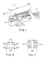
- Fig. 1 an automated sheet metal bending machine system 10 in which a material loader/unloader 100 is used to pick up a workpiece 102.
- the workpiece 102 is then taken from the material loader/unloader 100 by a five degree of freedom robot 104.
- the gripper 106 of the robot to which the fingerpad force sensor system of the present invention is secured, as will be discussed later herein, is used to grip the workpiece 102 and move it into position along the die rail 108 and against the backstops 110 of the press brake 112.
- the punch tools 114 are used to process the workpiece 102.
- the repositioning gripper 116 may be utilized.
- the workpiece 102 may be misaligned when acquired by the robot 104 at the material loading and unloading station 100 or when the robot 104 places the workpiece 102 into the press brake 112 for bending. Also, collisions occasionally occur between the workpiece 102 and the press 112, the robot 104 or other obstacles.
- An additional common manufacturing process variation is the slippage between the workpiece 102 and the gripper 106 of the robot 104, which can occur when the robot 104 accelerates too quickly while gripping a large workpiece 102.
- the fingerpad force sensor of the present invention as shown, for example, in Figs. 2 and 3, has been developed in order to provide real time compensation for those manufacturing process variations.
- the fingerpad force sensor system of the present invention will assist the robot 104 in properly aligning the workpiece 102, detecting and/or recovering from a collision between the workpiece and various components of the automated sheet metal bending system 10 and to prevent slippage of the workpiece 102 while in the gripper 106 of the robot 104.
- the foregoing goals can be achieved by integrating the fingerpad force sensing system hardware and software with that of the automated sheet metal bending machine 10.
- the hardware of the fingerpad force sensor system that is, the fingerpad force sensors 210 and the associated signal condition circuit board 1000, interface with the computer 1006 of the sheet metal bending machine by means of an analog-to-digital converter board 1002 and a digital output board 1004.
- the digital output board 1004 allows the bending machine's computer 1006 to control the offset nulling functionality of the force sensor's signal conditioning circuit board 1000.
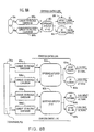
- the integration of the fingerpad force sensor system of the present invention with an automated metal bending machine is shown in Fig. 10.
- the fingerpad force sensor's software includes routines that permit the bending machine's computer 1006 to read the sensor output values, to convert the sensor output voltage values to equivalent force units, to control the offset nulling module of the signal conditioning circuit board 1000, and to perform sensor-based control strategies.
- the sensor software consists of a three-level hierarchy. At the lowest level is the first-level device drive software 1104 for the analog-to-digital board 1002 and the digitable output board 1004.
- the first-level device drivers define the commands that allow the bending machine's computer 1006 to communicate with the analog-to-digital board 1002 and the digital output board 1004.
- the next level 1102, called the second-level device driver software contains the device driver for the fingerpad sensor system.
- the sensor system's second-level device driver embodies the routines that allow the bending machine's computer 1006 to communicate with the signal conditioning circuit board 1000 of the fingerpad force sensor, including routines to read and convert the sensor outputs and to activate the offset nulling module of the signal conditioning board 1000.
- the second-level device driver builds upon the commands defined by the first-level device driver.
- the third level of software 1100 contains the real time application routines that are embedded in the bending machine's overall application software (e.g., the execution sequencer).
- the fingerpad force sensor's application routines include sensor-based control strategies for force sensing, as well as data acquisition routines.
- the application program uses the software routines defined in the second-level device drivers as building blocks for the more elaborate application routines. This is a common software paradigm which is described, for example, in CHIMERA II Real Time Programming Environment: Program Documentation, by David B. Stewart, Donald E. Schmitz, and Pradeep K. Khosla, released in 1991 by Carnegie Mellon University, at pages 154-167.
- a bent workpiece 102 may collide with the punch tool 114 when the robot 104 tries to remove it from the press brake 112. That collision causes a large and abrupt change in the sensor signals, which can be used to initiate a sensor-based control routine to help the bending machine recover from the collision.
- the sensor routine can also be used to interrupt the robot program such that the robot 104 moves away from the punch tool 114. That prevents damage to the workpiece 102, the robot 104, the punch tool 114 and the sensors 210.
- the sensor routine may then notify the process planner of the error and can then be used to adjust the path of the robot 104 by utilizing the sensor's information concerning the impact force direction in order to recover from a collision between the punch tool 114 and a bent workpiece 102. Also, the robot 104 can be instructed to move along the newly adjusted path using feedback obtained from the sensors 210 in order to "feel" its way out of the press brake 112.
- the fingerpad force sensor system of the present invention uses both the detection of the error during the manufacturing process and a sensor-based control scheme for compensating for a sensed error in order to prevent such an error from recurring.
- the fingerpad force sensor of the present invention is mounted to the gripper 106 of the robot 104.
- one set of sensors can be utilized for numerous force sensing applications.
- the gripper 106 of the robot 104 is an ideal place of the mounting of the force sensors since forces are transferred from the workpiece 102 to the gripper 106 when the workpiece 102 interacts with its environment.
- the set of the force sensors 210 travels with the workpiece 102 and is always present to measure the forces which affect the workpiece 102, and especially those which occur during the procedure of loading the workpiece 102 into the press brake 112 for bending.
- Each of the force sensors 210 is formed as integral component of the robot's parallel-jaw gripper 106 and forms, in effect, a fingerpad for the robot 104.
- the fingerpad force sensor of the present invention is fabricated by mounting one or more position-sensitive detectors 206 (only a single position-sensitive detector is shown for purposes of clarity) in an aluminum mounting plate 202. The aluminum mounting plate 202 is then secured to the bottom half 106b of the gripper 106 of the robot 104 using the existing screw holes (not shown) of the gripper 106.
- a rubber pad 200 having a recess 212 cut in it is mounted to a thin sheet metal base plate 304 by, for example, an adhesive.
- the base plate 304 has a hole cut in it to allow the light from the LED 300 to reach the position-sensitive device 206.
- the rubber pad 200 and its base 304 are secured to the top surface of the aluminum mounting plate 202 with screws 306.
- another rubber pad 208 may be likewise mounted to the aluminum plate to make the gripping surface even.
- a number of other rubber pads 208 may be mounted with an adhesive to the sheet metal base plates 204 which are in turn fastened to the gripper top 106a by any suitable means, such as with screws (not shown).
- the light from the LED 300 of the rubber pad 200 can be centered on the position-sensitive detector 206 by moving the rubber pad 200 and its base plate 304 within the confines of enlarged screw through holes by which the rubber pad base-plate is attached to the aluminum plate 202.
- the aluminum mounting plate 202 can be designed in such a way that small set screws can be inserted into its sides to push the position-sensitive device 206 into a centered position relative to the sensor pad LED 300.
- the aluminum mounting plates 202 are mounted to the bottom gripper 106b by suitable devices, such as the screw 308 shown in Fig. 3.
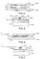
- Fig. 3 shows an enlarged portion of Fig. 2 which includes the rubber pad 200 having a recess 212 formed therein, as well as the position-sensitive detector 206 mounted on its aluminum plate 202.
- the force sensor 210 is formed from, for example, a one-dimensional position sensitive detector having a sensitive area of preferably 1 mm x 3.5 mm.
- a two-dimensional position-sensitive detector is utilized.
- the one-dimensional position-sensitive detector may be Part No. S3274-01 available from Hamamatsu Photonics KK of Japan.
- the two-dimensional position-sensitive detector may be Part No. S4744, also available from the same company.
- the infrared light emitting diode (LED) 300 which is embedded in the rubber pad 200 in that portion of the rubber pad 200 which bridges the recess 212 may preferably be a miniature 2 mm wide LED Part No. LD261-5 for use with the one-dimensional sensor and a miniature 1 mm wide LED, Part No. SFH405-3, for use in the two-dimensional sensor. Both of those components are available from Siemens Components, Inc. of Cupertino, California.
- the sensor 210 is designed such that when an external force acts on a workpiece 102 held by the gripper 106, the rubber pad deforms, thus causing LED 300 to shift along the sensitive area of the position-sensitive detector 206.
- the position-sensitive detector 206 detects the shifting the light source, as shown in Figs. 4 and 5, and the electrical output from the position-sensitive detector 206 is affected.
- Fig. 4 is a diagram of a cross-section of the instant force sensor 210 under a shear load F which issue applied to the left-hand side of the workpiece 102 which is gripped by the rubber pads 208 and 200. For purposes of simplicity, not all of the remaining components shown in Fig. 2 are shown in Fig. 4.
- Fig. 5 is an enlargement 500 of a portion of Fig. 4, including the rubber pad 200 which carries the LED 300, showing the skewed relationship between the LED 300 and the position-sensitive detector 206 when the shear load F is applied to workpiece 102 as shown in Fig. 4.
- the changes in the output from the position-sensitive detector 206 can then be utilized to determine the amount of force experienced by the workpiece 102 and its direction of application. It is preferred that the sensors 210 have a measurement resolution of at least 1 pound and a of range at least 10 pounds in each sensing direction.
- a typical rubber pad 200 may preferably measure 1/2 in. x 1 in. x 3/8 in. in size for the 1-D sensors (and 1 x 1 x 3/8 for 2-D sensors) and have a recess 212 cut into it for the LED 300 as well as a channel 302 for the wires connected to the LED 300.
- An epoxy adhesive may be utilized to embed the LED 300 into the rubber pad 200.
- the process of embedding the LED 300 into the rubber pad 200 involves removing as little rubber material as possible from the pad 200 and utilizing only a small amount of epoxy cement such that the mechanical properties of the rubber pad 200 do not change substantially.
- at least two one-dimensional sensors 210 are utilized on the front end of the gripper 106.
- Fig. 6 shows a diagram of a top view of the front end of the gripper 106. While the instant invention is described with the sensors 210 being secured to the gripper bottom 106b and the rubber pads 208 being secured to the gripper top 106a, it should be understood that the sensors 210 could alternatively be secured to the gripper top 106a while the rubber pads 208 could be secured to the gripper bottom 106b or the sensors 210 could be secured to both the top and bottom of the gripper 106.
- Fig. 7 shows a diagram of a top view of the front end of the gripper 106 illustrating the location and orientation of four two-dimensional force sensor 210a.
- the four two-dimensional sensors 210a are mounted to a mounting plate in a similar manners described in connection with the mounting of the sensors 210 to the mounting plate 202 in Fig. 2.
- the four two-dimensional sensors 210a and measuring the differences between the outputs from the top and bottom sets of sensors 210a it may be possible to distinguish between shear and normal forces being applied to the workpiece 102.
- the direction and magnitude of the forces detected by the top and bottom sensors is similar when shear forces are applied in the plane of the sensors 210a, while the magnitude and direction differs when a normal force is applied to the workpiece 102.
- the typical shear forces monitored by the sensors 210 and 210a assure 11b to 10 lbs.
- the rubber used to form the pads 200 and 208 may preferably be made from neoprene rubber having a 45 Shore A hardness rating. It has been found that such rubber pads exhibits both hysteresis and a creep characteristics, which effect the response time and recovery time of the sensor.
- the creep characteristic of the rubber pad 200 also results in a slow settling time for the sensor's output when the gripper 106 of the robot 104 first closes.
- the slow settling time of the sensor output can be reduced by pre-loading the sensor with a compression force greater than the typical nominal gripping force of 300 psi.
- a look-up table can be developed which contains the average change in the sensor's output for each different applied load. Such a table would include the changes that occurred during both the loading and unloading of the sensor, that is, changes due to both creep and recovery.
- Such a look-up table could be utilized with software used in connection with the output signals produced by the instant fingerpad force sensor system.
- a rubber pad can alternatively be made from castable urethane, also having a 45 Shore A hardness rating, by pouring liquid urethane into a mold into which the LED 300, its associated wires and the pad base-plate 304 have already been fixed in place. The rubber pad is then formed as the urethane cures. That method of manufacturing the sensor 210 minimizes the variability between LED-embedded rubber pads and ensures that the LED is located in the center of the rubber pad and is perpendicular to the position-sensitive detector 206.
- Liquid urethane is available from, for example, Conap, Inc., of Olean, New York under the Part No. CONATHANE TU-500.
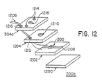
- Fig. 12 shows an alternative and preferred sensor pad design for use with the fingerpad force sensor system of the present invention (shown upside down).
- This design offers several improvements over the previously described LED-embedded rubber pad. Its improvements include easier fabrication, more accurate placement of the LED 300 in the sensor pad, and better shear displacement under a load.
- this alternative approach uses three layers of material to form the sensor pad 200a. The three layers are formed from a cork-rubber pad 1200, a copper surface printed circuit board (PCB) 1202, and a rubber pad 1204 made of natural gum rubber.
- PCB copper surface printed circuit board
- the cork-rubber pad 1200 provides a good gripping surface and absorbs the oils used on the sheet metal parts moved by the robot 104.
- the dimensions of the cork-rubber pad are preferably 1" x 1" x 1/16".
- the copper surface printed circuit board 1202 holds the LED 300 and connects the LED 300 to power and ground sources through the wires 1206.
- a line 1208 is etched away from the copper surface of the PCB 1202 in order to electrically isolate the board into two copper sections (one section for power and other for ground).
- the LED 300 is then snugly fitted into a hole on the copper side of the printed circuit board 1202.
- the leads of the LED 300 are then soldered to the copper board one lead to each side.
- the wires 1206 are soldered to each copper section to supply the power and ground signals for the operation of the LED 300.
- the dimensions of the copper PCB 1202 board are preferably 1" x 1" x 1/16".
- the third layer consists of a natural gum rubber pad 1204 of 45 Shore A hardness having a hole 1210 cut out of its center to allow the light from the LED 300 to pass through to the position-sensitive detector 206, 206a and a second hole 1212 near the corner of the pad 1204 for the wires 1206 to feed through to the copper PCB 1202.
- the dimensions of the rubber pad 1204 are preferably 1" x 1" x 1/8".
- the sensor pad 200a is formed by placing the three layers 1200-1204 together using a suitable adhesive. More specifically, the cork rubber pad 1200 is attached to the non-copper side of the printed circuit board layer 1202 and the rubber pad 1204 is attached to the copper side of the printed circuit board layer 1202. The natural gum rubber side of the layered sensor pad 200a is then attached to a sheet metal base plate 304a with suitable adhesive.
- the base plate 304a has a hole 1218 cut in its center to allow the light from the LED 300 to pass through to position-sensitive detector 206, 206a, screw holes 1214 on each end for attaching the base plate 304a to the sensor's aluminum mounting plate 202, and a fourth hole 1216 near its corner for the wires 1206 to feed through to copper plate 1202.
- Fig. 8A shows a schematic diagram of a one-dimensional force sensor signal conditioning circuit which may be used to convert the photo-current output signals of the position-sensitive detectors 206 into voltage signals.
- the force sensor signal conditioning circuit produces two signals for each sensor, a DC-level signal for measuring forces applied to the sensor and an AC signal for detecting collisions.
- Each of the one-dimensional sensitive detectors produces two output currents i1 and i2 which are fed respectively to first and second current-to-voltage converters 800a and 800b, which convert those currents to voltage values v1 and v2.
- Those output voltages v1 and v2 are fed to a difference amplifier 802 which, by subtracting the voltage v2 from the voltage v1, determines the relative light position of the LED 300 on the photo-sensitive detector sensitive area 206.
- the output from the difference amplifier 802 is fed to both an offset nulling module 804 and to a DC filtering module 806.
- the offset nulling module 804 is connected to be controlled by the bending machine computer.
- the offset nulling module 804 functions to remove the large DC component of the difference output (v1-v2) which occurs when the gripper 106 closes and compresses the rubber pads 200.
- the DC filtering module 806 functions to pass only the transitions in that difference voltage for purposes of collision detection. All of the stages 800-806 also function to amplify the signals which are input to them.
- Each of the force sensors 210 utilizes a respective force sensor signal conditioning circuit such as that shown in Fig. 8.
- circuitry shown in Fig. 8A is modified accordingly.
- the modifications to the circuit shown in Fig. 8A are minimal for the two-dimensional (2-D) position-sensitive device (PSD) 206a since its operational properties are similar to the one-dimensional (1-D) PSD 206.
- PSD position-sensitive device
- the circuitry in Fig. 8A is duplicated two times (once for each sensing direction) and for each module the amplification gains and capacitor values are adjusted.
- Such circuitry is shown in Fig. 8B.
- circuitry which can be used with the current-to-voltage converters 800 is shown in Fig. 9A; circuitry for use as the differential amplifiers 802 is shown in Fig. 9B; circuitry for use as the DC filtering modules 806 is shown in Fig. 9C; and circuitry for use as the computer-controlled offset nulling models 804 is shown in Fig. 9D.
- the fingerpad force sensing system of the present invention is useful for correcting workpiece misalignment at the loading station and press brake, for detecting unplanned workpiece collisions and for detecting imminent workpiece slippage.
- Each of those applications and a suggested sensing strategy is described below and illustrated in Tables 1-3.
- the gripper 106 of the robot 104 is equipped with four two-dimensional force detectors 210a, as shown and described in connection with Fig. 7.
- the first application which will be discussed is that of the alignment of the workpiece at the loading station.
- the loader/unloader 100 picks up an unbent workpiece 102 with its suction cups and feeds sheet workpiece 102 to the robot 104 for bending, in a known manner.
- the workpieces 102 are usually aligned in their bin before the loader/unloader 100 picks them up, positional information may be lost due to mechanical imperfections in the loading mechanism.
- the workpiece 102 thus passed to the robot 104 will be skewed. If the misalignment of the workpiece is not corrected, then a crooked bend will result and the workpiece 102 will have to be discarded as scrap material.
- an L-shaped bracket as shown in Table 1, can be used to align the workpiece 102 at the loading station 100.
- the robot 104 can fit a corner of the workpiece 102 into the corner of the alignment bracket, whose position is accurately known by the bending machine 112.
- the degree of misalignment is determined by calculating the difference between the robot's position and orientation before and after aligning the workpiece 102.
- a position and orientation offset value is then added to all other robot moves throughout the manufacturing process in order to correct for the initial workpiece misalignment. Correction of the workpiece misalignment at the loading station thus minimizes or eliminates the necessity for realignment of the workpiece 102 at the press brake 112 for each bend.
- Table 1 illustrates a five-step alignment procedure and the forces indicated by the sensors 210a during the procedure while accomplishing the alignment of a corner of the workpiece 102 with the corner of the alignment bracket.
- Step 2 in Table 1 after contact of the workpiece 102 has been made with the bracket, the robot 104 rotates the workpiece 102 in a counter-clockwise direction around the contact point until the side of the workpiece 102 is in full contact with the left side of the bracket. After such contact has occurred, the sensor readings will indicate one of three possibilities. First, the moment forward of the pivot point is greater than the moment below the pivot point, such that the sensors 210a read resultant forces in a clockwise direction. Second, the opposing moments about the pivot point are equal, so that all four of the sensors 210a read a force in the -y direction and possibly a small force in the +x direction.
- the third possibility is that the moment behind the pivot point is greater than the moment in front of the pivot point, so that the sensors 210a read a resultant force in the counter-clockwise direction greater than the initial contact forces.
- the robot 104 then rotates the workpiece 102 clockwise or counter-clockwise, as necessary, in order to cancel the opposing moments acting on the workpiece 102.
- This step establishes the orientation of the workpiece 102 and makes it easier to detect contact with the corner of the bracket in the next step.
- the robot 104 moves the workpiece 102 back, while maintaining contact with the side of the bracket, until the workpiece 102 touches the corner of the bracket. Contact between the bracket and the workpiece 102 is indicated by a clockwise resultant force reading generated by the sensors 210a.
- This step establishes the position of the workpiece 102. As previously discussed, an offset value corresponding to the position and orientation of the workpiece 102 is then used throughout the manufacturing process to compensate for the loading process variation.
- Step 5 the final step in the alignment procedure, is to push the workpiece 102 away from the corner before the robot 104 executes its next move. This step removes any force moments acting on the workpiece and prevents the rubber pads which form part of the sensors 210a from "springing back" when the robot 104 eventually moves the workpiece 102 away from the alignment bracket.
- Table 2 illustrates the three steps and the resultant sensor force readings which are used to align the workpiece 102 in the press break 112 such that the robot 104 places the workpiece 102 snugly against the backstops 110 of the press break 112.
- the workpiece is bent. A straight bend is desired.
- the steps for aligning the workpiece 102 to the backstops 110 of the press brake 112 are similar to alignment task described above in connection with the loading station 100. This tasks differs, however, because a workpiece 102 can be loaded into the press brake 112 in two ways. The first way to load a workpiece 102 into the press brake 112 is with the gripper 106 perpendicular to the desired bend line.
- That type of loading is called front loading.
- the second type of loading is that in which the gripper 106 is parallel to the bend line.
- That type of loading is termed side loading.
- the steps for accomplishing the front loading are shown in Table 2A, while the steps for accomplishing side loading are shown in Table 2B.
- each loading technique requires a slightly different sensing strategy, the goal is the same, that is, to place the side of the workpiece 102 against the backstops 110 of the press back 112.
- the front loading alignment procedure has three steps, which are illustrated in Table 2A.
- the robot 104 moves the workpiece 102 forward into the press brake 112 until the workpiece touches the backstops 110. If the workpiece is misaligned, it will either touch the right corner of the right backstop, thus producing a clockwise moment, or the left corner of the left backstop, thus producing a counter-clockwise moment.
- the point of contact can be determined, since the position of the backstops 110 is known.
- the robot 104 then rotates the workpiece 102 about the point of contact until it touches both backstops 110.
- the robot 104 adjust the position of the workpiece 102 until the opposing moments acting on workpiece 102 are within the desired tolerance. The workpiece 102 is thus aligned and the press brake 112 can then proceed to bend the workpiece.
- the robot 104 rotates the workpiece 102 towards the press brake 112 in order to ensure that the workpiece strikes the backstop 110 farthest from the gripper 106.
- the robot 104 then moves the workpiece 102 into the press brake 112 until the workpiece 102 touches the corner of the farthest of the two backstops 110.
- the robot 104 rotates the workpiece 102 about the point of contact until the workpiece 102 touches the second backstop 110.
- the robot 104 only manipulates the workpiece 102 until it touches both backstops 110.
- the robot 104 does not attempt to balance the opposing moments applied to the workpiece 102. Since contact of the workpiece 102 with both backstops 110 is indicated only by an increase in the measured force since there is no change in the force direction, supplementary contact sensors may also be utilized on each backstop 110.
- the fingerpad force sensing system of the present invention can also be utilized to detect impacts. That is desirable since such detection can prevent damage to the robot 104, the punch and die tools 108, 114 and the workpiece 102.
- the detection of an unplanned collision indicates that there is an error in the process planner software of an unanticipated process variation. Such errors, after being detected, can then be corrected before beginning the manufacturing process again with a new workpiece. It is therefore desirable to detect unplanned collisions with the workpiece 102 and, if possible, recover from those collisions by backing away from the impact.
- Table 3 shows an example of an unplanned collision between the workpiece or part 102 and an obstacle.
- the information generated by the sensors 210a in response to impact forces utilized.
- a threshold force value is set that is well above the noise level of the sensors 210a and the nominal sensor readings produced by mechanical vibrations in the manufacturing system. If a force grater than the threshold is registered by the sensors 210a during moves in free-space, then an impact has occurred.
- the sensor-based plan overrides the current robot 104 motion plan and, using the impact direction information obtained from the sensors 210a, moves the robot 104 away from the obstruction. Then, depending upon the robot motion in progress at the time of the collision, the sensors 210a may or may not be used to finish the desired robot move.
- the right corner of the workpiece 102 has incurred an unplanned collision with an unknown obstacle in what would normally be a "safe" or open space region with no known obstacles.
- the robot motion planner can then use the information generated by the sensors 210a to move the workpiece 102 over further to the left and then to try the front loading procedure again.
- the signals produced by the sensors 210a can be used to help the robot 104 "feel" its way out of the press brake 112.
- each force sensor's signal conditioning circuit namely a DC-level output for measuring forces and an AC signal that passes only the transitions in the force readings. That AC output can be used for impact detection by setting a threshold force value for a severe collision.
- the AC signal generated by the sensors 210a reaches preset thresholds, it can be used to trigger a system interrupt to stop the robot 104.
- the AC signal can be used as a safeguard that generates a hardware interrupt to shut down the robot 104 and the bending machine 112 upon the detection of a severe collision.
- the fourth detection application discussed above is that of detecting the workpiece 102 slipping within the gripper 106 of the robot 104 while the robot is rotating quickly. Such slippage occurs when the force acting on the workpiece 102 exceeds the frictional force between the rubber pads of the fingerpad force sensing system and the workpiece 102. If a workpiece 102 slips in the gripper 106, then information regarding the position of the workpiece 102 and its orientation is lost.
- the fingerpad force sensing system of the present invention can be used to prevent workpiece slippage by warning the robot system of an impending slippage condition. This warning mechanism can be used to control the speed or acceleration of the robot 104. For example, in order to operate efficiently, the robot 104 may be instructed to the move workpiece 102 as fast as it can until the sensors 210a generate a signal which is used to instruct the robot to decrease its speed since the workpiece 102 may be about to slip.
- the mechanism for detecting imminent workpiece slippage is similar to that discussed in connection with the detection of an impact.
- a force threshold that is below the nominal frictional force between the rubber pads and the sheet metal workpiece 102 may be used.
- the sensors 210a register a force at or above that threshold, the workpiece 102 is about to slip and the robot 104 is warned/instructed to slow down.
- the information generated by the fingerpad force sensor system of the present invention may be used in an open-loop system within the position-based control system of the robot 104. For example, during the alignment tasks as discussed above, the robot 104 is moved a small increment and then the values of the sensors 210a are read. Based on the signals generated by the sensors 210a, the next move of the robot 104 is determined.
- the information generated by the sensors 210a can be tied into the control loop of the robot 104 in order to improve the effectiveness of the sensors 210a and the response of the robot 104 to contact forces.
- a force-based control loop can be placed around the position controller of the robot 104. That can be accomplished by relating the desired incremental force with the desired incremental robot position through a proportionality constant.
- Such a scheme is termed a position-based proportional force control scheme, an example of which is shown in Table 4.
- This system operates as follows. When the motion of the robot 104 is constrained, for example, and the robot has pushed the workpiece 102 up against the backstops 110 of the press back 112, the robot controller can switch over to the force control scheme to assist the robot 104 in adjusting its movements until the desired force reading is reached.
- Such a method is desirable because it provides a natural way of implementing the application tasks, minimizes the possibility of missing an important event, such as an impact, and also eliminates the possibility of applying excessive forces to the workpiece 102.
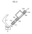
- the movement of the robot that grips a workpiece is appropriately controlled also during a bending operation in the workpiece. That is to say, as shown in FIG. 13, when a workpiece 102 gripped by the grippers 106a, 106b is being bent by a punch P and die D of the press brake 112, the workpiece 102 may be pulled by the punch P and die D in a direction indicated by A in FIG. 13. At this time, a shear force experienced by the workpiece 102 is detected by the sensors 210 provided in the grippers 106a, 106b.
- a signal of the sensor 210 is then transmitted to a controller to control the movement of the robot, and the gripper 106a, 106b is moved in the direction A so that the shear force experienced by the workpiece disappears.
- the workpiece 102 gripped by the grippers 106a, 106b is prevented from slipping between the grippers during the bending operation.
- the possible slippage of the workpiece relative to the grippers causes a problem that the controller that controls the robot looses the memory of a correct gripping position of the workpiece gripped by the grippers, that is, the problem that a gripping position of the workpiece stored in a memory of the controller differs form the actual gripping position of the workpiece gripped by the grippers.
Landscapes
- Physics & Mathematics (AREA)
- General Physics & Mathematics (AREA)
- Engineering & Computer Science (AREA)
- Mechanical Engineering (AREA)
- Manipulator (AREA)
- Bending Of Plates, Rods, And Pipes (AREA)
- Force Measurement Appropriate To Specific Purposes (AREA)
- Controlling Sheets Or Webs (AREA)
Claims (16)
- Kraftsensor zum Messen von Scherkräften, angewandt auf eine Platte eines ebenen Materiales, wobei der Kraftsensor aulweist:gekennzeichnet dadurch, daßein Stück (200) von ebenem Material;eine Ausnehmung (212), gebildet in dem Stück von ebenem Material;eine Lichtquelle (300); undeinen Positionserfassungs- Detektor (206, 206a), derart montiert, daß Licht, emittiert durch die Lichtquelle, auf den Positionserfassungs- Detektor auftrifft.
das ebene Material verformbar ist,
die Lichtquelle in der Ausnehmung des Stückes von verformbaren Material montiert ist,
der Positionserfassungs- Detektor benachbart zu der Ausnehmung montiert ist, und Scherkräfte, die auf die Platte aus ebenem Material aufgebracht werden, eine Verformung des Stückes aus verformbarem, ebenen Material verursachen, um so einen Auftreffort von Licht auf den Positionserfassungs- Detektor zu bewegen. - Kraftsensor von Anspruch 1, dadurch gekennzeichnet, daß die Lichtquelle eine infrarotes Licht emittierende Diode ist.
- Kraftsensor von Anspruch 1 oder 2, dadurch gekennzeichnet, daß das Stück aus verformbarem, ebenen Material aus einem Material gebildet ist, das eine Shorehärte von A 45 hat.
- Kraftsensor eines der Ansprüche 1 bis 3, außerdem gekennzeichnet durch eine Basisplatte (304), in der der Positionserfassungs- Detektor ausgenommen ist und an dem das Stück aus verformbarem, ebenen Material befestigt ist.
- Kraftsensor eines der Ansprüche 1 bis 4, dadurch gekennzeichnet, daß das Stück aus verformbarem, ebenen Material über dem Positionserfassungs- Detektor befestigt ist, derart, daß sich ein Ausgangssignal des Positionserfassungs- Detektors ändert, wenn die Scherkraft auf das Stück aus verformbarem, ebenen Material aufgebracht wird.
- Kraftsensor von Anspruch 5, außerdem gekennzeichnet durch einen Verarbeitungsschaltkreis, um das Ausgangssignal von dem Positionserfassungs- Detektor zu empfangen und um Signale zu erzeugen, die repräsentativ für die Größe und Richtung der Kraft und das Auftreten eines Aufschlages, erfahren durch den Kraftsensor, sind.
- Kraftsensor von Anspruch 6, dadurch gekennzeichnet, daß der Verarbeitungsschaltkreis aufweist:eine Mehrzahl von Strom- zu- Spannung- Umwandlem (800a, 800b, 800a2, 800b1, 800b2) zum Umwandeln der Ausgangssignale des Kraftsensors in Ausgangsspannungen;einen Differenzverstärker (802, 802a, 802b) zum Erfassen der Ausgangsspannungen und um ein Differenzsignal aus diesem zu erzeugen;einen computergesteuerten Versatz- Null- Schaltkreis (804, 804a, 804b), um das Differenzsignal aufzunehmen und um ein Gleichstrom- Signal zu erzeugen, dass die von dem Kraftsensor erfahrene Scherkraft repräsentiert.einen Filterschaltkreis (806, 806a, 806b) zum Aufnehmen des Differenzsignales und zum Herausfiltem einer Gleichstromkomponente, derart, dass ein Wechselstromsignal, repräsentativ für den von dem Kraftsensor erfahrenen Aufschlag erzeugt wird.
- Kraftsensor eines der Ansprüche 1 bis 7, dadurch gekennzeichnet, daß der Kraftsensor zweidimensionale Positionserfassungs- Detektoren enthält.
- Kraftsensor eines der Ansprüche 1 bis 8, außerdem gekennzeichnet durch:wobei das zweite Stück von ebenem Material mit seinem Bodenabschnitt an der Bodenoberfläche des ersten Stückes von ebenem Material befestigt ist;ein erstes Stück von ebenem Material, das ein Werkstück berührt; undein zweites Stück von ebenem Material, das einen Bodenabschnitt von dielektrischem Material und einen oberen Abschnitt von elektrisch leitendem Material hat,
wobei die Lichtquelle (300) an dem elektrisch leitenden oberen Abschnitt des zweiten Stückes von ebenen Material befestigt ist; und
die Ausnehmung, gebildet in dem Stück von verformbarem ebenen Material eine Öffnung ist, um darin Licht, emittiert durch die Lichtquelle, zu gestatten, dort hindurchzugehen, wobei das Stück von verformbaren ebenen Material an dem oberen Abschnitt des zweiten Stückes von ebenen Material befestigt ist. - Roboter, gekennzeichnet durch:einen Greifer (106) zum Halten eines Werkstückes (102); undzumindest einen Fingerdruckkissen- Kraftsensor (210, 210a) eines der vorhergehenden Ansprüche.
- Roboter von Anspruch 10, dadurch gekennzeichnet, daß der Sensor entsprechend einem der Ansprüche 1 bis 9 aufgebaut ist.
- Roboter von Anspruch 10 oder 11, außerdem gekennzeichnet durch eine Einrichtung zum Bestimmen eines Kraftgrenzwertes und um zu erfassen, daß ein Aufschlag oder eine Kollision aufgetreten ist, wenn eine durch den Sensor erfaßte Kraft größer als die Kraftgrenzwert ist.
- Roboter von einem der Ansprüche 10 bis 12, dadurch gekennzeichnet, daß vier der Fingerdruckkissen- Kraftsensoren auf einer Seite des Greifers befestigt sind, jeder ungefähr gleichbeabstandet von einem Mittelpunkt auf der einen Seite des Greifers.
- Roboter von einem der Ansprüche 10 bis 13, der ein Roboter für eine Biegepresse ist, wobei die Biegepresse ein Paar Werkzeuge (P, D) hat, die miteinander zusammenwirken, um ein dazwischen vorgesehenes Plattenwerkstück (102) zu biegen,
wobei der Roboter ein Paar von Greifem (106a, 106b) hat, die angepaßt sind das Werkstück dazwischen zu greifen und zumindest mit einen Fingerdruckkissen-Kraftsensor (210) zum Erfassen einer Scherkraft, erfahren von dem Werkstück, vorgesehen sind, wobei die Vorrichtung aufweist:eine Einrichtung, um den Roboter mit einem Signal zu versehen, um das durch die Greifer zwischen dem Werkzeugpaar gegriffene Werkstück anzuzeigen;eine Einrichtung, um die Biegepresse mit einem Signal zum Biegen des Werkstückes durch das Werkzeugpaar zu versehen;eine Einrichtung, um von dem Sensor ein Signal aufzunehmen, das die Scherkraft, erfahren durch das Werkstück während des Biegens, anzeigt; undeine Einrichtung, um den Roboter mit einem Signal zu versehen, um den Roboter in eine geeignete Richtung zu bewegen, so daß die Scherkraft, erfahren von dem Werkstück, verschwindet. - Roboter von einem der Ansprüche 10 bis 14, der in der Lage ist, durch
eine Steuerung gesteuert, um eine Scherkraft auf das durch den Greifer gehaltene Werkstück auszuüben, und eine Verformung der Fingerdruckkissen- Kraftsensors in Abhängigkeit von der durch das Werkstück erfahrene Scherkraft zu erfassen. - Roboter von einem der Ansprüche 10 bis 15, der ein Roboter für ein Biegepressen ist, wobei der Roboter in der Lage ist durch eine Steuerung gesteuert zu werden, um ein Werkstück zwischen den Greifern zu greifen, das Werkstück zwischen dem Werkzeugpaar zu präsentieren, das Werkstück durch ein Werkzeugpaar zu biegen, eine Scherkraft, erfahren durch das Werkstück während des Biegens, zu erfassen, und den Roboter in eine geeignete Richtung zu bewegen, so daß die von dem Werkstück erfahrene Scherkraft verschwindet.
Priority Applications (1)
| Application Number | Priority Date | Filing Date | Title |
|---|---|---|---|
| EP02002208A EP1236546A3 (de) | 1994-11-09 | 1995-11-09 | Verfahren und Vorrichtung zur Steuerung eines Greifers |
Applications Claiming Priority (3)
| Application Number | Priority Date | Filing Date | Title |
|---|---|---|---|
| US33809594A | 1994-11-09 | 1994-11-09 | |
| US338095 | 1994-11-09 | ||
| PCT/JP1995/002288 WO1996014968A1 (en) | 1994-11-09 | 1995-11-09 | Shear force sensing system |
Related Child Applications (1)
| Application Number | Title | Priority Date | Filing Date |
|---|---|---|---|
| EP02002208A Division EP1236546A3 (de) | 1994-11-09 | 1995-11-09 | Verfahren und Vorrichtung zur Steuerung eines Greifers |
Publications (2)
| Publication Number | Publication Date |
|---|---|
| EP0738200A1 EP0738200A1 (de) | 1996-10-23 |
| EP0738200B1 true EP0738200B1 (de) | 2003-02-12 |
Family
ID=23323389
Family Applications (2)
| Application Number | Title | Priority Date | Filing Date |
|---|---|---|---|
| EP95936759A Expired - Lifetime EP0738200B1 (de) | 1994-11-09 | 1995-11-09 | Scherkraftmesssystem |
| EP02002208A Withdrawn EP1236546A3 (de) | 1994-11-09 | 1995-11-09 | Verfahren und Vorrichtung zur Steuerung eines Greifers |
Family Applications After (1)
| Application Number | Title | Priority Date | Filing Date |
|---|---|---|---|
| EP02002208A Withdrawn EP1236546A3 (de) | 1994-11-09 | 1995-11-09 | Verfahren und Vorrichtung zur Steuerung eines Greifers |
Country Status (5)
| Country | Link |
|---|---|
| US (2) | US5844146A (de) |
| EP (2) | EP0738200B1 (de) |
| JP (1) | JP3727657B2 (de) |
| DE (1) | DE69529603T2 (de) |
| WO (1) | WO1996014968A1 (de) |
Cited By (3)
| Publication number | Priority date | Publication date | Assignee | Title |
|---|---|---|---|---|
| EP1301140B2 (de) † | 2000-04-19 | 2017-07-05 | OraMetrix, Inc. | Biegemaschine für eine medizinische Vorrichtung |
| DE102016013890A1 (de) * | 2016-11-21 | 2018-05-24 | Rheinisch-Westfälische Technische Hochschule (Rwth) Aachen | Verfahren zur Bestimmung der Achslast auf Linear- und Rundachsen |
| EP4134182A1 (de) | 2021-08-10 | 2023-02-15 | Fraunhofer-Gesellschaft zur Förderung der angewandten Forschung e.V. | Rollprofilierverfahren |
Families Citing this family (55)
| Publication number | Priority date | Publication date | Assignee | Title |
|---|---|---|---|---|
| DE69529603T2 (de) * | 1994-11-09 | 2003-06-26 | Amada Co., Ltd. | Scherkraftmesssystem |
| US5835684A (en) | 1994-11-09 | 1998-11-10 | Amada Company, Ltd. | Method for planning/controlling robot motion |
| US5761940A (en) | 1994-11-09 | 1998-06-09 | Amada Company, Ltd. | Methods and apparatuses for backgaging and sensor-based control of bending operations |
| DE69529607T2 (de) | 1994-11-09 | 2003-09-18 | Amada Co., Ltd. | Intelligentes system zur herstellung und ausführung eines metallplattenbiegeplans |
| US5798748A (en) * | 1995-06-07 | 1998-08-25 | Spacetec Imc Corporation | Force and torque converter with improved digital optical sensing circuitry |
| US6350242B1 (en) | 1995-09-28 | 2002-02-26 | Data Sciences International, Inc. | Respiration monitoring system based on sensed physiological parameters |
| EP0957757A1 (de) | 1995-09-28 | 1999-11-24 | Data Sciences International, Inc. | Anordnung zum überwachen der atmung mit hilfe von blutdruck-signalen |
| DE59910907D1 (de) * | 1998-07-09 | 2004-11-25 | Siemens Ag | Anordnung und verfahren zur ermittlung einer relativen lage zweier objekte |
| US6269677B1 (en) | 1999-12-28 | 2001-08-07 | Abb T&D Technology Ltd. | Press brake back gauge finger |
| TW482078U (en) * | 2001-02-20 | 2002-04-01 | Hon Hai Prec Ind Co Ltd | Structure for rear position gauge |
| US6456901B1 (en) * | 2001-04-20 | 2002-09-24 | Univ Michigan | Hybrid robot motion task level control system |
| US6466843B1 (en) * | 2001-10-16 | 2002-10-15 | General Electric Company | Method and apparatus for lifting objects |
| DE50310212D1 (de) * | 2002-05-13 | 2008-09-04 | Trumpf Maschinen Austria Gmbh | Verfahren zum Betrieb einer Fertigungseinrichtung |
| US6938454B2 (en) * | 2002-05-13 | 2005-09-06 | Trumpf Maschinen Austria Gmbh & Co. Kg. | Production device, especially a bending press, and method for operating said production device |
| EP1542918B1 (de) * | 2002-09-26 | 2016-11-16 | Trumpf Maschinen Austria GmbH & CO. KG. | Greifeinrichtung mit mitteln zum detektieren von doppelzufuhr und ihr betriebsverfahren |
| US7348498B2 (en) * | 2003-07-17 | 2008-03-25 | Hewlett-Packard Development Company, L.P. | Partially voided anti-pads |
| US6955094B1 (en) * | 2003-07-18 | 2005-10-18 | Cleveland Medical Devices Inc. | Sensor for measuring shear forces |
| NL1027733C2 (nl) * | 2004-12-13 | 2006-06-14 | Vmi Epe Holland | Snijinrichting. |
| US8181540B2 (en) * | 2006-03-28 | 2012-05-22 | University Of Southern California | Measurement of sliding friction-induced vibrations for biomimetic tactile sensing |
| WO2007126854A2 (en) * | 2006-03-28 | 2007-11-08 | Alfred E. Mann Institute For Biomedical Engineering At The University Of Southern California | Biomimetic tactile sensor |
| WO2008103943A1 (en) * | 2007-02-22 | 2008-08-28 | Cypress Semiconductor Corporation | Improved cursor control device and method |
| US8272278B2 (en) * | 2007-03-28 | 2012-09-25 | University Of Southern California | Enhancements to improve the function of a biomimetic tactile sensor |
| WO2009023334A2 (en) | 2007-05-18 | 2009-02-19 | University Of Southern California | Biomimetic tactile sensor for control of grip |
| JP5003336B2 (ja) | 2007-07-31 | 2012-08-15 | ソニー株式会社 | 検出装置、ロボット装置、および入力装置 |
| EP2378884A2 (de) | 2009-01-22 | 2011-10-26 | Laboratorios Miret, S.A. | Verwendung kationischer tenside als akarizidmittel |
| DE102010005673A1 (de) * | 2010-01-26 | 2011-07-28 | INA - Drives & Mechatronics GmbH & Co. OHG, 98527 | Greifer für eine Handhabungseinrichtung |
| WO2012013577A1 (en) | 2010-07-26 | 2012-02-02 | Laboratorios Miret, S.A. | Composition for coating medical devices containing lae and a polycationic amphoteric polymer |
| US20130201316A1 (en) | 2012-01-09 | 2013-08-08 | May Patents Ltd. | System and method for server based control |
| CN104271322B (zh) | 2012-03-08 | 2016-09-21 | 品质制造有限公司 | 触敏机器人抓手 |
| US9605952B2 (en) | 2012-03-08 | 2017-03-28 | Quality Manufacturing Inc. | Touch sensitive robotic gripper |
| JP5859134B2 (ja) * | 2012-09-21 | 2016-02-10 | 株式会社安川電機 | 力センサおよび力センサを有するロボット |
| US9625333B2 (en) | 2013-03-15 | 2017-04-18 | President And Fellows Of Harvard College | Tactile sensor |
| JP6450923B2 (ja) * | 2013-12-20 | 2019-01-16 | パナソニックIpマネジメント株式会社 | 電子部品実装システムおよび電子部品実装方法ならびに電子部品実装装置 |
| US9316488B1 (en) * | 2014-04-04 | 2016-04-19 | Softronics, Ltd. | Force measurement system |
| JP6421015B2 (ja) * | 2014-11-10 | 2018-11-07 | 名古屋油化株式会社 | マスキング材および該マスキング材の製造方法 |
| CN104483056B (zh) * | 2014-12-09 | 2017-02-01 | 郑州磨料磨具磨削研究所有限公司 | 一种超硬磨粒动态把持力测试系统及方法 |
| US10718359B2 (en) | 2015-08-21 | 2020-07-21 | Quality Manufacturing Inc. | Devices and systems for producing rotational actuation |
| EP3379222B1 (de) | 2017-03-22 | 2020-12-30 | Methode Electronics Malta Ltd. | Auf magnetoelastik basierte sensoranordnung |
| CN107297399B (zh) * | 2017-08-08 | 2018-10-16 | 南京埃斯顿机器人工程有限公司 | 一种机器人自动寻找折弯位置的方法 |
| EP3652721A1 (de) | 2017-09-04 | 2020-05-20 | NNG Software Developing and Commercial LLC | Verfahren und vorrichtung zum sammeln und verwenden von sensordaten von einem fahrzeug |
| EP3517888A1 (de) * | 2018-01-29 | 2019-07-31 | Sick Ag | Taktiles sensorsystem |
| DE18907724T1 (de) | 2018-02-27 | 2021-03-25 | Methode Electronics, Inc. | Schleppsysteme und Verfahren mit Verwendung von Magnetfeldmessung |
| US11135882B2 (en) | 2018-02-27 | 2021-10-05 | Methode Electronics, Inc. | Towing systems and methods using magnetic field sensing |
| US11491832B2 (en) | 2018-02-27 | 2022-11-08 | Methode Electronics, Inc. | Towing systems and methods using magnetic field sensing |
| US11084342B2 (en) | 2018-02-27 | 2021-08-10 | Methode Electronics, Inc. | Towing systems and methods using magnetic field sensing |
| US11221262B2 (en) | 2018-02-27 | 2022-01-11 | Methode Electronics, Inc. | Towing systems and methods using magnetic field sensing |
| US11014417B2 (en) | 2018-02-27 | 2021-05-25 | Methode Electronics, Inc. | Towing systems and methods using magnetic field sensing |
| CN110174196B (zh) * | 2018-04-10 | 2021-05-14 | 北京纳米能源与系统研究所 | 多应力传感的自驱动复合传感器 |
| WO2019244661A1 (ja) * | 2018-06-22 | 2019-12-26 | ソニー株式会社 | 制御装置、制御方法及びプログラム |
| CN109002596B (zh) * | 2018-06-28 | 2021-11-02 | 郑州云海信息技术有限公司 | 一种pcb中铜皮拐角转换实现方法及系统 |
| US12092544B2 (en) * | 2018-09-10 | 2024-09-17 | The University Of British Columbia | Optical force sensors |
| IT201900001187A1 (it) * | 2019-01-28 | 2020-07-28 | Univ Degli Studi Di Napoli Federico Ii | Elemento terminale per dispositivi di presa per interventi chirurgici, in particolare interventi a minima invasivita’ |
| WO2021126240A1 (en) * | 2019-12-20 | 2021-06-24 | Hewlett-Packard Development Company, L.P. | Printed circuit assembly detection |
| EP4286812A1 (de) * | 2022-06-03 | 2023-12-06 | Melexis Technologies SA | Weicher kraftsensor |
| US20240009864A1 (en) | 2022-07-05 | 2024-01-11 | GM Global Technology Operations LLC | Robotic end effector system and method with lockable compliance |
Family Cites Families (56)
| Publication number | Priority date | Publication date | Assignee | Title |
|---|---|---|---|---|
| US3438251A (en) * | 1965-07-26 | 1969-04-15 | Lord Corp | Optical transducer |
| US4369563A (en) * | 1965-09-13 | 1983-01-25 | Molins Limited | Automated machine tool installation with storage means |
| US4309600A (en) * | 1967-12-15 | 1982-01-05 | Cincinnati Milacron Inc. | Machine tool |
| US3654616A (en) * | 1970-06-29 | 1972-04-04 | Unimation Inc | Program selection arrangement for manipulator apparatus |
| US3890552A (en) * | 1972-12-29 | 1975-06-17 | George C Devol | Dual-armed multi-axes program controlled manipulators |
| GB1525044A (en) * | 1975-02-12 | 1978-09-20 | Bottomley A | Tool for working sheet metal |
| US4260940A (en) * | 1975-10-28 | 1981-04-07 | Unimation, Inc. | Programmable automatic assembly system |
| IT1122696B (it) * | 1979-08-02 | 1986-04-23 | Salvagnini Transferica Spa | Perfezionamento nelle presse-piegatrici |
| JPS5841927B2 (ja) * | 1979-10-25 | 1983-09-16 | 攻 牧野 | プレス曲げ加工用工具 |
| JPS57113116A (en) * | 1980-12-30 | 1982-07-14 | Fanuc Ltd | Robot control system |
| JPH065486B2 (ja) * | 1981-03-26 | 1994-01-19 | 株式会社安川電機 | ロボットの軌跡制御方法 |
| JPS5856003A (ja) * | 1981-09-30 | 1983-04-02 | Hitachi Ltd | 工業用ロボツトの制御方法 |
| US4501135A (en) * | 1982-02-09 | 1985-02-26 | L & F Industries | Stress sensor for yield-point detection in a stretch press |
| US4521685A (en) * | 1982-03-01 | 1985-06-04 | Lord Corporation | Tactile sensor for an industrial robot or the like |
| CH655874A5 (de) * | 1982-06-07 | 1986-05-30 | Haemmerle Ag Maschf | Werkzeugeinrichtung an einer abkantpresse. |
| JPS59114609A (ja) * | 1982-12-22 | 1984-07-02 | Hitachi Ltd | ロボットの制御装置 |
| JPS59189415A (ja) * | 1983-04-13 | 1984-10-27 | Hitachi Ltd | 工業用ロボツトの動作教示方法および装置 |
| US4588348A (en) * | 1983-05-27 | 1986-05-13 | At&T Bell Laboratories | Robotic system utilizing a tactile sensor array |
| CH654761A5 (fr) * | 1984-02-03 | 1986-03-14 | Beyeler Machines Sa | Presse-plieuse dont le dispositif de pliage permet un controle continu de l'angle de pliage de la piece a plier. |
| US4658625A (en) * | 1984-03-30 | 1987-04-21 | Amada Company, Limited | Bending machine and a die changing system for such bending machine |
| US5146670A (en) * | 1985-04-24 | 1992-09-15 | The Boeing Company | Profiling and deburring of workpieces |
| US4998206A (en) * | 1988-07-29 | 1991-03-05 | The Boeing Company | Automated method and apparatus for fabricating sheet metal parts and the like using multiple manufacturing stations |
| US4942767A (en) * | 1986-11-19 | 1990-07-24 | Massachusetts Institute Of Technology | Pressure transducer apparatus |
| US4745812A (en) * | 1987-03-25 | 1988-05-24 | The United States Of America As Represented By The Secretary Of The Army | Triaxial tactile sensor |
| US4802357A (en) * | 1987-05-28 | 1989-02-07 | The Boeing Company | Apparatus and method of compensating for springback in a workpiece |
| US4831549A (en) * | 1987-07-28 | 1989-05-16 | Brigham Young University | Device and method for correction of robot inaccuracy |
| US5092645A (en) * | 1987-09-18 | 1992-03-03 | Wacoh Corporation | Robotic gripper having strain sensors formed on a semiconductor substrate |
| DE3739173A1 (de) * | 1987-11-19 | 1989-06-01 | Feintool Int Holding | Verfahren und vorrichtung zum biegen von werkstuecken |
| GB2211002B (en) * | 1987-12-15 | 1992-01-08 | Amada Co Ltd | Device and method for controlling a manipulator for a plate bending machine |
| DE3902149C2 (de) * | 1988-01-29 | 2000-05-18 | Amada Co | Biegeeinrichtung und Verfahren zum Positionieren von Werkstücken in einer Blechbiegeeinrichtung |
| IT1219110B (it) * | 1988-03-15 | 1990-05-03 | Prima Ind Spa | Dispositivo manipolatore di pezzi di lamiera per una pressa piegatrice e procedimento per la fabbricazione di pezzi profilati di lamiera mediante piegatura alla pressa |
| US5047916A (en) * | 1988-03-25 | 1991-09-10 | Kabushiki Kaisha Toshiba | Method and apparatus of free space enumeration for collision avoidance |
| FR2630358B1 (fr) * | 1988-04-21 | 1993-12-10 | Picot Sa | Procede et dispositif pour le controle du retour elastique, lors du cintrage d'un element allonge tel que tube |
| AT389829B (de) * | 1988-05-03 | 1990-02-12 | Haemmerle Ag | Verfahren zum biegen von blechstuecken mit hilfe einer biegeeinrichtung |
| IT1219302B (it) * | 1988-05-16 | 1990-05-03 | Prima Ind Spa | Macchina per la fabbricazione di pezzi di lamiera piegata |
| US5031441A (en) * | 1988-07-29 | 1991-07-16 | The Boeing Company | Two arm robot |
| US4947666A (en) * | 1988-09-16 | 1990-08-14 | The Boeing Company | Method and apparatus for bending an elongate workpiece |
| IT1224044B (it) * | 1988-12-29 | 1990-09-26 | Prima Ind Spa | Pressa piegatrice di precisione per pezzi di lamiera lunghi |
| US5081763A (en) * | 1989-05-30 | 1992-01-21 | The Boeing Company | Automated drilling station |
| US5307282A (en) * | 1989-09-22 | 1994-04-26 | Hewlett-Packard Company | Method of computer-aided prediction of collisions between objects including fabrication tools and parts to be fabricated |
| JP2773917B2 (ja) * | 1989-09-22 | 1998-07-09 | 株式会社アマダ | ベンディング装置のワーク位置決め装置 |
| JP2727241B2 (ja) * | 1989-09-26 | 1998-03-11 | 株式会社小松製作所 | プレスブレーキシステムのワーク位置決め装置および方法 |
| JP2723994B2 (ja) * | 1989-10-06 | 1998-03-09 | 株式会社アマダ | ベンディング装置のゲージング処理方法 |
| US5009098A (en) * | 1989-11-27 | 1991-04-23 | Machinefabriek Wila B.V. | Press and curve-forming means therefor |
| IT1237750B (it) * | 1989-12-29 | 1993-06-15 | Prima Ind Spa | Procedimento di piegatura di una lamiera |
| US5261266A (en) * | 1990-01-24 | 1993-11-16 | Wisconsin Alumni Research Foundation | Sensor tip for a robotic gripper and method of manufacture |
| US5036694A (en) * | 1990-07-02 | 1991-08-06 | The Boeing Company | Method and apparatus for bending the flange of a workpiece |
| US5088181A (en) * | 1990-10-09 | 1992-02-18 | The Boeing Company | Sheet metal part machining system |
| JP2661395B2 (ja) * | 1991-04-09 | 1997-10-08 | ダイキン工業株式会社 | プレスブレーキシステムにおけるワーク位置決め方法およびその装置 |
| US5298964A (en) * | 1992-03-31 | 1994-03-29 | Geo-Center, Inc. | Optical stress sensing system with directional measurement capabilities |
| JP3181382B2 (ja) * | 1992-07-15 | 2001-07-03 | 株式会社アマダ | 折曲げ加工機のワーク位置決め装置 |
| IT1260677B (it) * | 1993-07-29 | 1996-04-22 | Antonio Codatto | Manipolatore per la movimentazione di lastre, particolarmente pannellidi lamiera, nei confronti di una macchina operatrice, quale una pressapiegatrice. |
| US5365059A (en) * | 1993-08-06 | 1994-11-15 | Bilanx Technology, Inc. | Parallel beam force measurement apparatus having an optical light sensor means |
| US5761940A (en) * | 1994-11-09 | 1998-06-09 | Amada Company, Ltd. | Methods and apparatuses for backgaging and sensor-based control of bending operations |
| US5835684A (en) * | 1994-11-09 | 1998-11-10 | Amada Company, Ltd. | Method for planning/controlling robot motion |
| DE69529603T2 (de) * | 1994-11-09 | 2003-06-26 | Amada Co., Ltd. | Scherkraftmesssystem |
-
1995
- 1995-11-09 DE DE69529603T patent/DE69529603T2/de not_active Expired - Fee Related
- 1995-11-09 EP EP95936759A patent/EP0738200B1/de not_active Expired - Lifetime
- 1995-11-09 JP JP51591196A patent/JP3727657B2/ja not_active Expired - Fee Related
- 1995-11-09 WO PCT/JP1995/002288 patent/WO1996014968A1/en not_active Ceased
- 1995-11-09 EP EP02002208A patent/EP1236546A3/de not_active Withdrawn
-
1996
- 1996-10-31 US US08/741,553 patent/US5844146A/en not_active Expired - Fee Related
-
1998
- 1998-11-13 US US09/190,211 patent/US6067862A/en not_active Expired - Fee Related
Cited By (4)
| Publication number | Priority date | Publication date | Assignee | Title |
|---|---|---|---|---|
| EP1301140B2 (de) † | 2000-04-19 | 2017-07-05 | OraMetrix, Inc. | Biegemaschine für eine medizinische Vorrichtung |
| DE102016013890A1 (de) * | 2016-11-21 | 2018-05-24 | Rheinisch-Westfälische Technische Hochschule (Rwth) Aachen | Verfahren zur Bestimmung der Achslast auf Linear- und Rundachsen |
| EP4134182A1 (de) | 2021-08-10 | 2023-02-15 | Fraunhofer-Gesellschaft zur Förderung der angewandten Forschung e.V. | Rollprofilierverfahren |
| DE102021208675A1 (de) | 2021-08-10 | 2023-02-16 | Fraunhofer-Gesellschaft zur Förderung der angewandten Forschung eingetragener Verein | Rollprofilierverfahren |
Also Published As
| Publication number | Publication date |
|---|---|
| JP3727657B2 (ja) | 2005-12-14 |
| JPH09509497A (ja) | 1997-09-22 |
| DE69529603D1 (de) | 2003-03-20 |
| DE69529603T2 (de) | 2003-06-26 |
| EP1236546A3 (de) | 2002-12-11 |
| US6067862A (en) | 2000-05-30 |
| US5844146A (en) | 1998-12-01 |
| WO1996014968A1 (en) | 1996-05-23 |
| EP1236546A2 (de) | 2002-09-04 |
| EP0738200A1 (de) | 1996-10-23 |
Similar Documents
| Publication | Publication Date | Title |
|---|---|---|
| EP0738200B1 (de) | Scherkraftmesssystem | |
| US6644080B2 (en) | Press brake worksheet positioning system | |
| US11633850B2 (en) | Tactile sensor module for robot-hand and grasping method using the same | |
| US6292716B1 (en) | Method and apparatuses for backgaging and sensor-based control of bending operations | |
| US4640663A (en) | Balancer and controlling method thereof | |
| EP4219093B1 (de) | Systeme und verfahren zur bereitstellung von kontaktdetektion in einem gelenkarm | |
| EP2868441A1 (de) | Robotersteuerung, Robotersystem und Roboter | |
| JP2003326486A (ja) | ワーク位置決め装置 | |
| EP0937974A3 (de) | Roboter und Verfahren zur Kalibrierung eines auf dem Roboter befestigten Kraftsensors | |
| WO2020209333A1 (ja) | ロボットハンド、ロボット及びロボットシステム | |
| US20200164512A1 (en) | Robot system and coordinate conversion method | |
| EP4596131A1 (de) | Abkantpresse, biegeverarbeitungssystem und verfahren zur steuerung der sensorbewegung | |
| JP2773917B2 (ja) | ベンディング装置のワーク位置決め装置 | |
| US20220203549A1 (en) | Suction pad and deformation measuring device | |
| GB2326491A (en) | Controlling tracking of robot along working path | |
| CN115605329A (zh) | 随动机器人 | |
| US6095396A (en) | Bonding load correction method and wire bonding apparatus | |
| JP3720099B2 (ja) | 曲げ加工機における板厚検出方法およびその装置並びに曲げ加工方法および曲げ加工機 | |
| JP2023151157A (ja) | 把持装置 | |
| CN220463963U (zh) | 用于机械手的二维测力传感器 | |
| KR20210087726A (ko) | 미세 로봇 관절용 센서장치 | |
| Murray | A Fingerpad Force Sensor For Manipulating Sheet Metal | |
| CN111054842B (zh) | 一种折弯上下料机器人轨迹自主生成方法 | |
| JP4543498B2 (ja) | パネルベンダ制御装置 | |
| JPH05123987A (ja) | 把持装置 |
Legal Events
| Date | Code | Title | Description |
|---|---|---|---|
| PUAI | Public reference made under article 153(3) epc to a published international application that has entered the european phase |
Free format text: ORIGINAL CODE: 0009012 |
|
| 17P | Request for examination filed |
Effective date: 19960808 |
|
| AK | Designated contracting states |
Kind code of ref document: A1 Designated state(s): DE |
|
| 17Q | First examination report despatched |
Effective date: 19991104 |
|
| GRAG | Despatch of communication of intention to grant |
Free format text: ORIGINAL CODE: EPIDOS AGRA |
|
| GRAG | Despatch of communication of intention to grant |
Free format text: ORIGINAL CODE: EPIDOS AGRA |
|
| GRAH | Despatch of communication of intention to grant a patent |
Free format text: ORIGINAL CODE: EPIDOS IGRA |
|
| GRAH | Despatch of communication of intention to grant a patent |
Free format text: ORIGINAL CODE: EPIDOS IGRA |
|
| GRAA | (expected) grant |
Free format text: ORIGINAL CODE: 0009210 |
|
| AK | Designated contracting states |
Designated state(s): DE |
|
| REF | Corresponds to: |
Ref document number: 69529603 Country of ref document: DE Date of ref document: 20030320 Kind code of ref document: P |
|
| PLBE | No opposition filed within time limit |
Free format text: ORIGINAL CODE: 0009261 |
|
| STAA | Information on the status of an ep patent application or granted ep patent |
Free format text: STATUS: NO OPPOSITION FILED WITHIN TIME LIMIT |
|
| 26N | No opposition filed |
Effective date: 20031113 |
|
| PGFP | Annual fee paid to national office [announced via postgrant information from national office to epo] |
Ref country code: DE Payment date: 20081223 Year of fee payment: 14 |
|
| PG25 | Lapsed in a contracting state [announced via postgrant information from national office to epo] |
Ref country code: DE Free format text: LAPSE BECAUSE OF NON-PAYMENT OF DUE FEES Effective date: 20100601 |