EP0738176B1 - Bewegbare spielfigur für brettspiel - Google Patents
Bewegbare spielfigur für brettspiel Download PDFInfo
- Publication number
- EP0738176B1 EP0738176B1 EP95905495A EP95905495A EP0738176B1 EP 0738176 B1 EP0738176 B1 EP 0738176B1 EP 95905495 A EP95905495 A EP 95905495A EP 95905495 A EP95905495 A EP 95905495A EP 0738176 B1 EP0738176 B1 EP 0738176B1
- Authority
- EP
- European Patent Office
- Prior art keywords
- playing
- section
- shaft
- game
- manipulating
- Prior art date
- Legal status (The legal status is an assumption and is not a legal conclusion. Google has not performed a legal analysis and makes no representation as to the accuracy of the status listed.)
- Expired - Lifetime
Links
- 230000007246 mechanism Effects 0.000 claims abstract description 20
- 210000002105 tongue Anatomy 0.000 description 9
- 238000010276 construction Methods 0.000 description 6
- 239000000463 material Substances 0.000 description 4
- 239000004033 plastic Substances 0.000 description 3
- 229920003023 plastic Polymers 0.000 description 3
- 239000002184 metal Substances 0.000 description 2
- DHKHKXVYLBGOIT-UHFFFAOYSA-N acetaldehyde Diethyl Acetal Natural products CCOC(C)OCC DHKHKXVYLBGOIT-UHFFFAOYSA-N 0.000 description 1
- 125000002777 acetyl group Chemical class [H]C([H])([H])C(*)=O 0.000 description 1
- 239000000853 adhesive Substances 0.000 description 1
- 230000001070 adhesive effect Effects 0.000 description 1
- 238000005452 bending Methods 0.000 description 1
- 230000035939 shock Effects 0.000 description 1
- 125000006850 spacer group Chemical group 0.000 description 1
Images


Classifications
-
- A—HUMAN NECESSITIES
- A63—SPORTS; GAMES; AMUSEMENTS
- A63F—CARD, BOARD, OR ROULETTE GAMES; INDOOR GAMES USING SMALL MOVING PLAYING BODIES; VIDEO GAMES; GAMES NOT OTHERWISE PROVIDED FOR
- A63F7/00—Indoor games using small moving playing bodies, e.g. balls, discs or blocks
- A63F7/06—Games simulating outdoor ball games, e.g. hockey or football
- A63F7/0684—Games simulating outdoor ball games, e.g. hockey or football with play figures slidable or rotatable about a vertical axis
-
- A—HUMAN NECESSITIES
- A63—SPORTS; GAMES; AMUSEMENTS
- A63F—CARD, BOARD, OR ROULETTE GAMES; INDOOR GAMES USING SMALL MOVING PLAYING BODIES; VIDEO GAMES; GAMES NOT OTHERWISE PROVIDED FOR
- A63F7/00—Indoor games using small moving playing bodies, e.g. balls, discs or blocks
- A63F7/22—Accessories; Details
- A63F7/36—Constructional details not covered by groups A63F7/24 - A63F7/34, i.e. constructional details of rolling boards, rims or play tables, e.g. frame, game boards, guide tracks
- A63F2007/3655—Collapsible, foldable or rollable parts
-
- A—HUMAN NECESSITIES
- A63—SPORTS; GAMES; AMUSEMENTS
- A63F—CARD, BOARD, OR ROULETTE GAMES; INDOOR GAMES USING SMALL MOVING PLAYING BODIES; VIDEO GAMES; GAMES NOT OTHERWISE PROVIDED FOR
- A63F2250/00—Miscellaneous game characteristics
- A63F2250/18—Use of resilient or deformable elements
- A63F2250/183—Foam
-
- A—HUMAN NECESSITIES
- A63—SPORTS; GAMES; AMUSEMENTS
- A63F—CARD, BOARD, OR ROULETTE GAMES; INDOOR GAMES USING SMALL MOVING PLAYING BODIES; VIDEO GAMES; GAMES NOT OTHERWISE PROVIDED FOR
- A63F7/00—Indoor games using small moving playing bodies, e.g. balls, discs or blocks
- A63F7/06—Games simulating outdoor ball games, e.g. hockey or football
- A63F7/0604—Type of ball game
- A63F7/0612—Basketball
-
- A—HUMAN NECESSITIES
- A63—SPORTS; GAMES; AMUSEMENTS
- A63F—CARD, BOARD, OR ROULETTE GAMES; INDOOR GAMES USING SMALL MOVING PLAYING BODIES; VIDEO GAMES; GAMES NOT OTHERWISE PROVIDED FOR
- A63F7/00—Indoor games using small moving playing bodies, e.g. balls, discs or blocks
- A63F7/06—Games simulating outdoor ball games, e.g. hockey or football
- A63F7/0604—Type of ball game
- A63F7/0632—Hockey
Definitions
- This invention relates to board game apparatus including game boards rehiring playing members to be moved over the surface of the boards by control rods.
- a variety of board games are known which require a number of playing pieces to be moved about the playing surface of the game board, often by means of some mechanical control mechanism such as a movable rod.
- the playing members are coloured or otherwise designed to represent two different teams of playing members.
- a well known game board of this type simulates the game of ice hockey and, in this particular game, there are five regular playing members on each team plus a goalie member that can be moved to protect the goal net from an incoming shot. In this game a small puck-like disc can be used and is movable around the board by the playing members.
- United States Patent No. 3,856,303 issued December 24, 1974 to Divid Games, Incorporated describes a game apparatus designed to simulate a basketball game. It also has a plurality of playing pieces that are movable along the playing surface by push rods slidably disposed under the game board and adapted to be operated at each end of the board. A basket-like device is arranged at each end of the board and is elevated above the playing surface. Small ramps are arranged on the board and these are used in conjunction with the playing pieces to raise the ball upwardly from the board in the general direction of the basket.
- a combination movable playing member and control mechanism therefor suitable for a board game comprising a base member and a movable manipulating member mounted to or in said base member, said base member and said manipulating member comprising the playing member, a shaft extending downwardly from said base member and sized to extend through a hole in a game board for said game, elongate tube means for moving said playing member relative to the game board, means for engaging said tube means with the shaft so that rotation of said tube means about its longitudinal axis causes a corresponding rotational movement of the shaft, said combination characterized by said shaft being hollow and by a flexible control line extending through said tube means and said shaft and into said base member, said line being connected at its inner end to said movable manipulating member and having means at other end of said tube means to enable said control line to be pulled and thereby pull said manipulating member in one direction, and means for biasing said manipulating member to move in a direction opposite to said one direction.
- a board game apparatus comprising a game board with a generally flat, upwardly facing playing surface and a number of combinations of the movable playing member and control mechanism as described above, each playing member being adapted to manipulate a small object for movement over or above said surface, characterized in that each base member is a body portion that extends upwardly from said playing surface, each manipulating member is an object manipulating portion pivotally connected to its respective body portion, said flexible control line comprises means for pivoting each manipulating portion relative to its respective body portion, each shaft extends vertically, each elongate tube means extends in a substantially horizontal direction and is provided for moving its respective playing member along a respective slot formed in said playing surface, and further including means for rotatably supporting each tube means below said playing surface.
- the game apparatus disclosed herein can be adapted to simulate a variety of sports-related games including basketball, hockey, football, soccer, baseball and cricket.
- a playing member on the simulated basketball court can be controlled to move horizontally across the game board, turn or pivot and raise arms. Because the arms can be raised or lowered, they can be used to block a ball, catch a ball, and to throw or shoot the ball.
- the players are manipulated by rods or tubes located under the playing surface in a manner similar to known simulated ice hockey games.
- the arms of a playing member can be raised by pulling on a control button arranged at the outer end of that player's control tube. This in turn pulls a control wire or line which raises the arms to an elevated position.
- each playing member has a manipulating portion which can be pivoted about a horizontal axis in a manner which permits this portion to strike an adjacent puck device or disc. Because of this pivoting action, it is possible to actually lift the puck device off of the playing surface and to more accurately control the power and direction of both passes and shots on goal.
- the slots in the game board are arranged in a particularly advantageous manner.
- Each half of the game board has at least five elongate slots extending generally in the lengthwise direction with two of these being formed on the left hand side of a longitudinal centre line, two being formed on the right hand side and the fifth slot being formed in the region of the centre line itself.
- At least one of the left hand slots and at least one of the right hand slots are formed with bends in central longitudinal regions of the slots so that two adjacent playing members arranged to move along either the left hand slots or the right hand slots can move closer together or further apart along the central regions and can interact one another in these central regions when they are closer to each other. This permits the playing members to "tackle" one another and to take the puck or ball away from the opposing playing member.
- a game board apparatus constructed in accordance with the invention can be made to more accurately simulate the real sport game. Moreover, the game board apparatus of the present invention can be made in an inexpensive manner to keep the costs of the game reasonable.
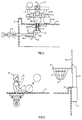
- Figure 1 illustrates a board game apparatus 10 laid out in the manner of a basketball court.
- the apparatus comprises a game board 12 having a generally flat, upwardly facing playing surface 14.
- a number of game playing members 16 are mounted on the playing surface and are capable of being moved parallel to the playing surface or horizontally in order to play the game. These playing members preferably depict a human figure or a partial figure, in this case a basketball player.
- each playing member includes a body portion 18 that extends upwardly from the playing surface and an object manipulating portion 20 pivotally connected to the body portion 18. As explained hereinafter, there are means for pivoting the manipulating portion 20 relative to the body portion.
- the object to be manipulated is a small ball that may depict or simulate a basketball.
- the object of this basketball game is to shoot the ball 22 through one of two basket members 24.
- Each of these basket members has an open bottom 26 that enables the ball 22 to fall through the basket member in the same manner that it does in a real basketball game.
- the basket members are located at two opposite ends of the game apparatus and they are elevated above the playing surface 14 as shown in Figure 3.
- each basket member is mounted on an upright, rigid panel 28 which can act as a backboard against which the ball can be bounced.
- the panel 28 is supported on an upright post 30 which in turn is supported by a centrally located post support 32 that can be formed on or attached to an end wall 34.
- the support 32 forms a socket with an open top and a closed bottom with the socket sized to closely accommodate the post 30.
- the preferred ball 22 is a small, sponge rubber ball that is light enough to be lifted by the playing member 16.
- the ball would normally have a diameter of 2 inches or less and in one preferred embodiment the diameter is about 1 inch.
- the diameter of the ball must be significantly less than the diameter of the rim 36 of the basketball net.
- the diameter would normally be slightly less than the diameter of the opening 26 in the bottom of the net device.
- the preferred form of the ball is made from low density sponge rubber.
- a number of slots 38 to 42 are formed in the game board 12 to allow for movement of the playing members 16.
- the slots are formed in a horizontal panel portion 48 of each section and they preferably extend to an inner edge 50 thereof so that the slots are open-ended at this inner edge. At least the majority of the slots 38 to 42 extend a major portion of the length of their respective principal section.
- two slots 38, 39 are formed on the left hand side of the longitudinal centre line of the section and two slots 41, 42 are formed on the right hand side of this longitudinal centre line.
- the fifth slot 40 is formed in the region of the longitudinal centre line.
- the two left hand slots 38, 39 and the two right hand slots 41, 42 are formed with bends forming obtuse angles in their central longitudinal regions.
- the slots are so formed that two adjacent playing members either in the left hand slots or the right hands slots can come closer together along the central regions compared to other slots regions on opposite sides of the central regions and can contact one another in the central regions.
- This arrangement of the slots is to improve the "flow" and play of the game. With this slot arrangement, each playing member has an area of safe-haven where he cannot be tackled or effectively blocked by another playing member of the opposite team.
- the slot 38 has a short curved section 52 near a rounded corner 54 of the game board and large obtuse angles formed by bends at 56, 58 and 60. There is a fourth bend forming a large obtuse angle at 62. With these bends, the slot has three straight sections 63 to 65 which are in substantially parallel alignment. It will be further noted that the slot 38 has a short extension at 66 which is formed in the other half section 46.
- the slot 39 has three bends forming obtuse angles at 68 to 70 with the bends at 69 and 70 being shown as sharper than those in the slot 38 but it will be understood that these two bends could form larger obtuse angles.
- the sections of the slot 39 at 71 and 72 can be in substantially parallel alignment while an initial section 74 of the slot extends parallel to the longitudinal centre line of the section.
- the preferred slot has two bends at 76 and 78 which form obtuse angles.
- slot end sections at 80 and 82 are in parallel alignment and are parallel to the longitudinal centre line of the section 44 or 46.
- the outer slot 42 has an initial straight section 84 and then there are four slight bends 85 to 88 forming large obtuse angles. Both the central slot 40 and the slot 42 have end extensions 90 and 92 formed in the opposite half section 46.
- the inner right hand slot 41 has a relatively short, straight initial section 94 and three bends 95 to 97 forming large obtuse angles.
- the five main slots in the other half section 46 are formed and laid out in a similar manner as shown and these slots also have some slot extensions in the half section 44.
- FIG 1 Also shown in Figure 1 are a number of substantially horizontal rod means 100 which are provided for moving the playing members 16, there being one rod means for each playing member.
- rod means 100 In the illustrated basketball game there are five such rod means projecting from each end of the game board and it will be understood that these rod means extend through openings formed in each end wall of the game board, these openings being similar to the openings shown in Figure 19.
- the surface 14 is surrounded by an upwardly extending perimeter wall 104, a portion of which is formed by the end walls 34, one of which is illustrated in Figure 3.
- the perimeter wall 104 extends downwardly from the playing surface as illustrated in Figure 5.
- Each principal section can be formed with short supporting legs 106 and 108 to elevate the playing surface a suitable distance above the ground or table on which the apparatus is supported.
- the playing support surface is further supported by transversely extending ribs indicated at 109 and 110. These ribs must be formed with suitable openings below the playing surface to permit the passage of the movable rod mechanisms 100.
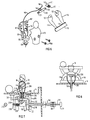
- the manipulating portion 20 includes two spaced-apart arm sections 114 and 116, a ball engaging section 118 extending between and connecting the two arm sections at their outer ends, and a horizontal shaft section 120 shown in Figure 6.
- the section 120 extends between and connects the arm sections at their inner ends and it has two non-circular end sections 121 and 122 which are fitted into correspondingly shaped holes 123 formed in the arm sections.
- the ball engaging section 118 is substantially straight and it has an elongate recess 124 formed in its upwardly facing surface to make ball manipulation easier.
- the shaft Extending downwardly from the body portion 18 is vertical shaft means 126 and it is this shaft which extends down through the playing surface via the respective slot.
- the playing member is pivotably mounted by means of this vertical shaft.
- the shaft which is hollow, preferably is formed with two or more vertically extending slots 128, which slots are designed to provide a shock absorbing capability. By providing this capability, contact between the playing members is less likely to cause damage to the playing member or its support.
- These slots 128 should not be unduly large so that they will not weaken the shaft to such an extent that it could fail during play of the game.
- first gear 130 preferably a bevelled gear.
- Each preferred rod means 100 includes a hollow tube and a second gear 132, also preferably a bevelled gear, is fixedly mounted on the inner end of this tube.
- the second gear operatively engages the first gear of the respective playing member.
- a bent coil spring instead of using the gears 130 and 132 to turn the axis of rotation, one can instead use a bent coil spring in a known manner to accomplish the same objective (see Figure 10 of the drawings).
- a tube support member 134 Arranged between the shaft 126 and the tube is a tube support member 134, the details of which can be seen from Figure 4.
- This member has a short passageway 135 located in a sleeve portion 136 and it is through this passageway that an inner end section of the tube 100 extends.
- the tube is free to rotate in this passageway.
- An angle portion 137 connects the bottom portion 136 to the shaft embracing section 138.
- the section 138 forms a vertical passageway at 140 through which the shaft means 126 extends.
- the shaft embracing section 138 is made from two halves which are detachably connected together by means of small bolts or screws 142.
- Outwardly extending arms 144 are formed on one half of the section 138 and these help keep the shaft means 126 and its playing member vertical.
- a flexible control line 146 is used and this line extends through the tube or rod 100, through the bevel gears 132, 130, through the vertical shaft means 126 and up into the main body portion 18.
- the line 146 is connected at its inner end 148 to the pivotable body portion 20 and in particular to the aforementioned shaft section 120 which is formed with a cantilever arm 150.
- a preferred form of the control line is one moulded from acetal, a plastics material which will not shrink if it becomes wet. Because the line is moulded, it can be formed with an end knob at one or both ends to help secure the line to the connecting part. One such knob is shown at the end 148 of Figure 6.
- control line 146 can be moulded with a thinner section 152 in the region of the line where the line bends upwardly between the inner end of the tube or rod and the vertical shaft and the remainder of the line can be made substantially thicker to permit ease of handling in the assembly of the control mechanism.
- the thinner section 152 can be no more than 1 mm thick and, in one preferred embodiment, it has a diameter of 0.030 inch (0.75 mm).
- the thicker portions of the line could, for example, be cross-shaped in cross-section and have a transverse dimension of 6 mm with a 1 mm leg thickness.
- a preferred form of enabling means is illustrated in Figure 4 and it includes a movable knob 156 which can be formed with a circumferential rim 157 that can be readily grasped by a player's fingers.
- the centre of this knob is hollow with a cylindrical passageway extending axially through it at 158.
- One end of this passageway may be split by a diagonally extending cross-piece 160 which connects the line 146 to the knob.
- the knob 156 is adapted to slide on the outer cylindrical surface of a short guide member 162.
- This member 162 is fixedly connected to the outer end of the tube or rod 100 by means of a connecting portion 164 which is of reduced diameter as compared to a longer, central section 165 on which the knob 156 slides.
- the diameter of the portion 164 corresponds closely to the internal diameter of the tube 100 and adhesive may be used to connect these two members.
- Both portions 164 and 165 are split by a longitudinally extending slot 166 into which the cross-piece 160 can slide.
- the guide member 162 is also formed with an end flange 168 so as to permit this member to be easily grasped between two fingers.
- both the tube 100 and the control line can vary in length depending upon the particular playing member that they are designed to control. For example, typically the tube 100 could vary in length from 385 mm to 744 mm.
- a spring biasing means in the form of a small coil spring 170. It will be understood that this coil spring fits over one end of the shaft section 120 and its inner end 171 is secured at a suitable location to this shaft section. Its outer end 172 is suitably secured to the main body section of the playing member, for example, in a slot 174 formed inside this body section.
- the spring is provided to bias the pivotable body section of the player to the lowered position, that is so that the ball engaging section 118 is immediately adjacent the playing surface.
- the player's arms can be raised by simply pulling on the movable knob 156 the desired amount. Upon release of this knob, the arms and the section 118 will return to the lowered position.
- a body section for a basketball player is illustrated in Figure 6 and it includes a frontal section 176 and a rear section 178, these two sections being detachably connected by means of small bolts or screws 180.
- the rear section 178 is formed with two, spaced apart C-shaped holders 181 and 182 adapted to support and secure the rounded portions of shaft section 120 which will snap into these holders.
- the rear section 178 is also provided with a circular base portion 183 which rests on the playing surface of the game board.
- the vertical shaft 126 is rigidly attached to the centre of this base portion.
- FIGs 7 and 8 illustrate an alternative construction for the controlling mechanism for each basketball playing member.
- the same reference numerals will be used to indicate components of the playing member that are constructed in substantially the same manner as that shown in Figures 2 and 6.
- the manipulating portion 20 is pivotally connected to a main body portion 18 which can rotate about a vertical axis defined by vertical shaft means 126.
- Fixedly mounted on the bottom end of this vertical shaft is a first bevelled gear 130 which engages a second bevelled gear 132 mounted on an inner end of a tubular member 184, a portion of which is broken away for sake of illustration.
- a knurled sleeve 186 can be fixedly mounted on the outer end of member 184 to permit easy rotation of the tubular member about is longitudinal axis.
- the inner end of the tubular member is rotatably supported by means of a Y-shaped support member 188 having tubular upper extension 190 sized to slide easily in a slot formed in the panel that forms playing surface 14.
- the Y-shaped member 188 has two downwardly extending support arms 192.
- the means for pivoting the manipulating portion of the playing member relative to the body portion 18 includes a straight, elongate first rod member 194 which extends through the tubular member 184 and out both ends thereof.
- a ramp member 196 with an inclined upper surface 198 is connected to the inner end of the rod 194 and is positioned below the respective playing member.
- a second vertically extending rod member 200 extends between the inclined upper surface 198 and the manipulating portion 20 whereby axial movement of the first rod member 194 is converted into vertical movement of the second rod member in order to pivot the manipulating portion.
- the second rod member 200 extends through the centre of the vertical shaft 126. It may be formed with an enlarged, rounded bottom end 202 and it may be formed with an elbow 204 at the top to enable it to engage a forwardly inclined lever 206 which is located inside the main body portion 18 and midway between the arm sections 114 and 116.
- a coil spring 208 extends around a cylindrical, central section of the ramp member and rests against one of the arms 192 at one end. This spring biases the ramp member and the attached rod to the right as seen in Figure 7.
- the ramp member 196 is further supported by the left arm 192 by means of a short flat-sided extension 210 extending through a matching hole in arm 192.
- the extension 210 is non-circular in cross-section in order to prevent rotation of the ramp member 196.
- An end cap 212 can be used to secure the extension 210 in the hole 220.
- the outer end of the first rod member 194 is fitted with a knurled knob 214 to permit easy manipulation by the user's fingers.
- Rotation of the tube 184 about its axis will rotate the gears and thereby cause rotation of the playing member about a vertical axis. Also, by pushing the rod member 194 inwardly, one can cause the playing member to lift its arm sections and the attached ball engaging section.
- the second rod member 200 should be made with a non-circular cross-section or vertically extending ribs so that it cannot rotate about its longitudinal axis in the vertical shaft 126.
- the central passageway extending through the shaft 126 must have a corresponding non-circular cross-section.
- a spacer or sleeve such as those indicated at 216 and 218 should be used to space the wide end of each bevel gear from the adjacent surface of the Y-shaped support member.
- the vertically extending rod member 200 could be made of a stronger material such as a suitable metal.
- the present invention can also be incorporated into a board game designed to simulate the sport of ice hockey and the game board for such a game is illustrated in Figures 9, 18 and 19.
- the hockey game board 222 is in many respects similar to the basketball game board described above and the same reference numerals will be used to indicate components which have the same or similar construction.
- the hockey game board has a flat, upwardly facing playing surface 14 on which a number of playing members 224 (see Figures 10 to 14) can be moved in order to manipulate a small object 226 which can be a disc or puck-shaped member having two, opposing flat sides.
- the board has a number of elongate slots formed therein for guiding the movement of the playing members 224 and, except for the differences noted hereinafter, these slots can be generally arranged in the same manner as already described in connection with the game board 12 of Figure 1.
- the right hand slots 228 and 230 are somewhat different in the ice hockey version of the game.
- the long slot 230 on the extreme right it has a rounded 90 degree bend 232 near the adjacent outer end of the board. This bend leads to an end section 234 that extends substantially parallel to the adjacent outer end of the board and that is behind simulated hockey net 236.
- the slot 228 has only two bends at 237 and 238, both forming large, obtuse angles. A long, straight section 239 of this slot extends to a point at the rear of the net 236. Some contact between the playing members of these two slots is thus permitted to the rear of the net.
- the ice hockey game is provided with an extra slot 240 at each end of the playing surface in front of the simulated hockey net.
- a suitable goalie member is movable in each of these slots by means of an extra control rod mechanism 242 located in the region of one of the adjacent corners of the game apparatus.
- the goalie member can be constructed in a similar manner to goalie members used in rod hockey games used in the past and it of course can be configured to have the appearance of a hockey goalie, ie. thick pads along the legs and a wider hockey stick.
- the control rod mechanism 242 can be a simple control rod or tube with no control line passing therethrough. In the alternative, it could be constructed in a similar manner to the other playing members but configured to have the appearance of a goalie.
- Figure 19 illustrates on end of the game board apparatus and shows a number of keyhole like apertures 244 to 248 formed in end wall 250 to hold and support the five rod means 100 that are used to control and operate the five playing members (apart from the goalie member) that form one team.
- the apertures 244 to 248 are formed with a large circular top section at 252 sized to permit passage of the larger end portions of the rod means during assembly of the game.
- the bottom portion of each aperture is narrower and sized to snugly accommodate the tube of the rod means which can be pushed into this portion.
- a suitable button member 254 can be pushed into the top section 252 to hold the rod means in the bottom portion of the aperture.
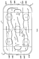
- Figure 18 shows one half of the bottom of a preferred game board apparatus for a hockey game.
- the five long slots formed in the horizontal panel include the aforementioned slots 228 and 230.
- Figure 18 also illustrates an alternative slot construction 256 for the goalie member wherein the slot is simply a curved arc spaced in front of the location for the goal net.
- Figure 18 illustrates how the region around the slots in the playing surface can be strengthened by means of ribs 262 located on both sides of each slot and spaced therefrom. If the playing surface is made from a plastics material, these ribs can be easily moulded onto the bottom of the panel forming the playing surface.
- the playing member 224 has a manipulating portion 264 which includes an elongate bent member 266 having an end section 268 extending parallel to the playing surface 14.
- the elongate-bent member 266 of course simulates a standard hockey stick used in ice hockey. It will be noted that the member 266 is located entirely on one side of the vertical axis extending through the shaft 270 that extends through the game board.
- a short pivot pin 272 projects from a round vertical side 274 of the manipulating portion, which side is located away from the bent member 266.
- the portion 264 is pivotally mounted on a main body portion 276 which can be configured to simulate the lower body and legs of a hockey player.
- control line 282 Extending through one of these legs 277 is a passageway 278 through which the control line 282 extends.
- the control line can be similar in its construction to the previously described control line 146.
- the line passes through the centre of a first gear 130 and a second gear 132 (as illustrated in Figure 2).
- the second gear is mounted on the inner end of tubular member 184.
- the control line 282 passes through a bent coil spring 283 which is used in a known fashion to connect the tubular member 184 to the shaft 270.
- the spring 283 provides the means for turning the axis of rotation 90 degrees or substantially 90 degrees.
- the control line is operated in the same manner as already described in connection with Figure 4.
- a small spring 292 mounted in the cavity 284 biases the stick or bent member 266 to the lower position shown in Figure 14.
- a player can raise the member 266 to the position shown in Figure 10.
- Projecting from the circular vertical side 274 is a pin member 286 to which the control line 282 is connected and which acts as a stop to limit the pivotal movement of the manipulating portion 264.
- This pin member 286 projects into a deeper section 288 of the cavity in the main body portion, the deeper portion being sector shaped and extending between radially extending cavity walls 289 and 290.
- the spring 292 is positioned in shallow recess 294 which extends generally vertically to the base of the cavity 284.
- One end of the spring can be mounted in a small hole 296 located at the bottom of recess 294.
- the other end of the spring can be fixed in a small hole 298 located at one side of the side 274 of manipulating portion 264.
- the playing members of the present game have a third action which enables the playing member to perform a shot similar to the so called "slap-shot" in regular ice hockey.
- This action allows a playing member to lift the puck or disc off the playing surface 14 and to more accurately control the power of passes and shots.
- This unique capability of at least the regular playing members 224 can result in a faster and more realistic hockey board game.
- the bent member 266 is made from a suitable metal to give it added strength and some flexibility.
- the board game preferably comprises two principal sections 44 and 46 which are detachably connected to produce the complete game board.
- the slots (not shown in Figure 16 for ease of illustration) are formed in a horizontal panel portion 48 of each section and these slots extend to the aforementioned inner edge 50 so the slots are open-ended at this edge.
- the sections are connected together at their inner edges and there are means for rigidly connecting the sections together.
- each horizontal panel portion 48 has at least two panel tongues 300 projecting horizontally from the inner edge thereof together with at least two recessed edge sections 302 also in the inner edge 50.
- These tongues and recessed edge sections form part of the connecting means with the tongues of one panel portion 48 interengaging the recessed edge sections of the other panel portion. It will be appreciated by one skilled in the art that these tongues and recessed edge sections help to prevent relative transverse movement of one game board section relative to the other.
- the connecting means for the two sections preferably also include a tongue member 304 formed at an inner end of one of the support walls 104 adjacent the inner edge of the panel portion and a further recess 306 adapted to receive the tongue member 304 on the support wall of the other principal section.
- the recess 306 is formed at an inner end of this support wall. Located in this recess is a small ramp like projection 308 which is adapted to snap into a rectangular hole 310 formed in the tongue member 304. It will be appreciated that the tongue 304 and recess 306 prevent relative vertical movement of one principal section with respect to the other and the engagement between the projection 308 and the opening 310 holds the two sections together in a detachable manner.
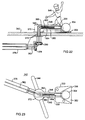
- the playing members that are moved along the two slots 230 which have a 90 degree bend at 232 employ a special rod means which is able to bend at the 90 degree bend.
- the bending mechanism for these particular playing members is illustrated in Figures 20 and 21 of the drawings.
- the relative lengths of the two rod sections 320 and 322 that make up this bendable rod means are illustrated by the dashed line which ends at the farthest position of the playing member located directly behind the opponent's goal net.
- the long section 320 is 744 mm measured from the outer end of the tube member to its inner end while the shorter section 322 is 111 mm measured between the two ends of the tube.
- the length of the rod sections actually used will depend upon the dimensions of the game board chosen.
- the two rod sections are connected together by means of a specially designed hinge member 324 made up of two pivotally connected parts 325 and 326. Rigidly connected to the top of part 326 is guide member 328 having a groove or slot 330 on each side thereof. It will be understood that the edges of the slot 230 fit into the grooves 330 and the guide member 328 is free to slide along the slot. It will be understood that the member 324 bends about a vertical axis X.
- Flanged sleeve members 332 and 334 are rotatably mounted in passageways formed in the member 324.
- the sleeve member 332 is rigidly connected to the inner end of rod section 320 while the sleeve member 334 is rigidly connected to the adjacent end of rod section 322.
- the adjacent ends of the two sleeve members are pivotally connected together by means of a coil spring 336 which extends through the vertical axis X.
- the flexible control line 146 extends through the coil spring 336 and through each of the sleeve members 332 and 334. It will be understood that because the sleeve members 332 and 334 are rotatable, rotation of the rod section 320 about its longitudinal axis is transmitted via the coil spring 336 to the rod section 322 in order to rotate the latter.
- the rules for playing the simulated hockey game with the apparatus of the invention can be similar to the rules for the sport of ice hockey or similar to the rules for previously known rod hockey games.
- the rules for the game of simulated basketball played with the apparatus of Figures 1 to 8 can be similar to the rules for regular basketball, modified to take into account the more limited degree of movement of the playing members 16 as compared to regular human players.
- the basketball game of the invention can simulate closely the play, strategy and excitement of regular basketball. By raising the arms of the playing members, these members can be used to block, tackle, dribble, throw and shoot the ball.
- playing members constructed in accordance with the invention can be made to represent and act like a cricket batman or a cricket bowler.
- playing members constructed in accordance with the invention can be made to represent and act like a batter and/or pitcher, and even like fielders in the case of a large game.
- Figures 22 and 23 illustrate a movable playing member that can be used in a simulated game of cricket, this playing member 340 acting as the bowler, that is the player that throws the ball toward the batsman.
- This playing member could also be used as a pitcher in a simulated baseball game.
- the playing member is designed to be mounted on a suitable game board 342 that has a slot 344 formed therein for the horizontal sliding movement of the bowler.
- the playing member 340 preferably includes a human figurine 346 but this figurine has no separate movement apart from the movement of the base member 348 on which it is mounted.
- the figurine 346 can be rigidly mounted on top of a horizontal plate 350 which is an extension of the base member 348.
- a shallow recess 352 is formed in plate 350 in order to receive and temporarily hold a small ball 354.
- the recess opens towards the front edge 356 of the plate.
- the ball 354 can be struck or rolled towards the batsman by means of a movable striking member 358 which is in the form of a pin member.
- the preferred base member in this embodiment includes a tubular section 360 that extends generally horizontally and that has a central passageway 362 to hold and guide the pin.
- the preferred biasing means is a coil spring 364.
- An annular shoulder or stop 366 is formed in the passageway and the rear end of the spring presses against this shoulder.
- the base member 348 has a short, downwardly extending, rear section 370 that includes a circular bottom flange 372.
- a hollow shaft 374 extends downwardly from the base member and is sized to extend through the slot 344 in the game board.
- An elongate tube or rod 376 is used to move this playing member relative to the game board.
- Two bevelled gears 378 and 380 are again used to engage the tube 376 with the shaft 374 so that rotation of the tube about its longitudinal axis causes a corresponding rotational movement of the shaft.
- a flexible control line 382 extends through the tube and the shaft and into the base member 348.
- This line is connected at its inner end to the rear end of the pin member 358 and thus acts to hold the pin member in the passageway against the force of the coil spring.
- the line 382 has means at the outer end of the tube 376 to enable the control line to be pulled and thereby pull the pin member 358 further into the passageway (away from the ball).
- the pin member is pushed quickly in the direction of the ball by the spring, thus causing the ball to roll in the direction of the batsman.
- a preferred form of the basketball game of the invention employs a game board measuring 30 inches by 18 inches and it is shaped and patterned like a basketball court.
- the basket rim is preferably 3 inches above the playing surface.
- a preferred height for the backboard is 10 cm from bottom to top.
- the present invention is also adaptable to make simulated board games similar to the games of soccer, baseball, cricket, football and golf.
- the pivoting manipulating portion of each playing member would represent the legs or leg of each soccer player.
- the batting player could be made to operate in a manner similar to the above described hockey player except that the pivot axis for the upper portion of the batter's body and the bat would extend at an angle (such as 45 degrees) to the horizontal plane.
- the players would resemble those used in the game of basketball, in that the players could throw, catch and move with the ball.
- the slots in the board would have a configuration that simulated the movement around the field made by real players and enable blocks and tackles to be made.
- the players would operate in a similar manner to the ice hockey player described above with a simulated golf club or putter substituted for a hockey stick.
- the batting player could also operate in a manner similar to the above described ice hockey player with a flat sided bat substituted for the hockey stick.
Landscapes
- Engineering & Computer Science (AREA)
- Multimedia (AREA)
- Pinball Game Machines (AREA)
- Toys (AREA)
Claims (14)
- Eine aus einer beweglichen Spielfigur und einem Steuermechanismus bestehende Kombination, die sich als Brettspiel eignet, da die besagte Kombination aus einem Standteil (18, 276, 348) und einem beweglichen Bedienelement (20, 264, 358) besteht, das an oder im besagten Standteil (18, 276, 348) befestigt ist. Das besagte Standteil und das besagte Bedienelement umfassen die Spielfigur, eine Welle (126, 270, 374), die von dem besagten Standteil aus nach unten weist und so dimensioniert ist, daß sie durch ein Loch in einem zum besagten Spiel gehörenden Spielbrett paßt, verlängerte Rohrteile (100, 184, 376), mit denen die besagte Spielfigur relativ zum Spielbrett bewegt werden kann, Bauteile (130, 132, 283, 378, 380) mittels derer die besagten Rohrteile mit der Welle durch Ineinandergreifen verbunden werden, so daß das Drehen der besagten Rohrteile entlang ihrer Längsachsen eine entsprechende Drehbewegung der Welle verursacht; diese besagte Kombination besteht aus der besagten Welle (126, 270, 374), d.h. einer Hohlwelle, und einer biegsamen Steuerleitung (146, 282, 382), die durch die besagten Rohrteile und die besagte Welle führt und im Standteil (18, 276, 348) endet. Das innen sitzende Ende (148) der besagten Leitung ist mit dem beweglichen Bedienelement (20, 264, 358) verbunden. Am anderen Ende der besagten Rohrteile (100, 376) besitzt sie Bauteile (156), mit deren Hilfe die besagte Steuerleitung gezogen werden kann, um so das Bedienelement in eine Richtung zu ziehen, sowie Bauteile (170, 292, 364) zum Lenken, damit das besagte Bedienelement in die der besagten Richtung gegenüberliegende Richtung bewegt werden kann.
- Die Kombination gemäß Anspruch 1 mit dem besagten Standteil (348), das mit einem runden Abschnitt (360) versehen ist, der sich generell horizontal ausdehnt; das besagte Bedienelement (358) ist ein im besagten runden Abschnitt gleitend befestigtes Stiffteil und das besagte Lenkteil ist eine Wickelfeder (364), die im besagten runden Abschnitt rückwärtig zum besagten Stiftteil angebracht ist und worin die besagte Leitung durch die besagte Wickelfeder (364) läuft und mit dem hinteren Ende des besagten Stiftteils verbunden ist.
- Die Kombination gemäß Anspruch 1 mit dem besagten Standteil besteht aus einem Hauptkörperabschnitt (18, 276), dem besagten Bedienelement in Form eines drehbaren Abschnitts (20, 264), der mit dem besagten Hauptkörperabschnitt verbunden ist, und der besagten Leitung, die an ihrem innen sitzenden Ende mit dem besagten drehbaren Abschnitt verbunden ist, um das besagte Drehen in eine Richtung zu ermöglichen.
- Die Kombination gemäß Anspruch 3 mit dem besagten Eingreifteil, das aus einem ersten Zahnrad (130) besteht, das an der besagten Welle (126, 270) angebracht ist, und aus einem zweiten Zahnrad (132), das ortsfest an einem innen sitzenden Ende der besagten Rohrteile (100, 184) befestigt ist, wobei das zweite Zahnrad (132) und das erste Zahnrad (130) betriebsbedingt ineinandergreifen.
- Die Kombination gemäß Anspruch 3 mit der besagten Freigabevorrichtung besteht aus einem beweglichen Knopf (156), der gleitend auf einem kurzen Führungsteil (162) befestigt ist, das an den besagten Rohrteilen (100, 184) angebracht ist, und zwar an deren anderen Enden.
- Die Kombination gemäß Anspruch 5 mit den besagten Lenkteilen (170, 292) besteht aus einer Feder, die zwischen dem besagten Hauptkörperabschnitt (18, 276) und dem besagten drehbaren Abschnitt (20, 264) angebracht ist, um den besagten drehbaren Körperabschnitt in eine ausgewählte normale Position zu lenken.
- Die Kombination gemäß Anspruch 4 mit den besagten ersten und zweiten Zahnrädern (130, 132) besteht aus Kegelrädern; die besagte Kombination besteht aus einem Rohrstützteil (134) mit einem kurzen Verbindungsgang (135), in dem das besagte innen sitzende Ende des besagten Rohrteils (100) drehbar befestigt ist, wobei das besagte Stützteil selbst durch die besagte Welle (126) gestützt wird.
- Die Kombination gemäß jedweder der Ansprüche 3 bis 7 mit dem besagten Bedienelement (264), das aus einem verlängerten Schlagteil (266) besteht, das mit einem schmalen, sich vertikal ausdehnenden Abschnitt und einem Endabschnitt (268) versehen ist, die so gestaltet sind, daß sie sich parallel zur Spielfläche des besagten Spielbretts verlängern, wobei das besagte verlängerte Schlagteil (266) sich ganz auf einer Seite einer Hauptachse der besagten Welle (270) befindet, und ein horizontaler Drehzapfen (272) verbindet den besagten drehbaren Abschnitt (264) mit dem besagten Hauptkörperabschnitt (276).
- Die Kombination gemäß Anspruch 5 mit der besagten Steuerleitung (146, 282), die aus einem dünneren Abschnitt (152) besteht, an dem sich die Leitung zwischen dem besagten innen sitzenden Ende der besagten Rohrteile (100, 184) und der Welle (126, 270) nach oben biegt; das verbleibende Stück der besagten Leitung ist wesentlich dicker.
- Ein Brettspielgerät, das aus einem Spielbrett (12, 222) mit einer generell flachen, nach oben zeigenden Spielfläche (14) und mehreren Kombinationen der sich bewegenden Spielfigur und dem Steuermechanismus gemäß Anspruch 1 besteht, wobei jede Spielfigur so gestaltet ist, daß mit ihr ein kleiner Gegenstand über oder entlang der besagten Fläche bewegt werden kann; jedes Standteil besteht aus einem Körperabschnitt (18, 276), der von der besagten Spielfläche aus nach oben weist; jedes Bedienelement ist ein den Gegenstand bewegendes Teil (20, 264), das drehbar am zu ihm gehörenden Körperteil befestigt ist; die besagte biegsame Steuerleitung besteht aus Bauteilen (146, 282), die jeden Bedienabschnitt (20, 264) relativ zum dazugehörigen Körperabschnitt drehen, jede Welle (126, 270, 374) ist vertikal ausdehnbar, jedes verlängerte Rohrteil (100, 184) dehnt sich beträchtlich in horizontale Richtung aus und dient zum Bewegen der ihm zugeordneten Spielfigur (16, 224) entlang eines entsprechenden Schlitzes, mit dem die besagte Spielfläche versehen ist; sowie Bauteile (34, 134) zum drehbaren Abstützen jedes Rohrteils unterhalb der besagten Spielfläche.
- Ein Spielgerät gemaß Anspruch 10 mit einem Innenabschnitt, der zur besagten Steuerleitung gehört und mit den besagten Bedienelementen (20, 264) verbunden ist, und einem Außenende der besagten Steuerleitung, das mit der Freigabevorrichtung (156) verbunden ist, die gleitend am Außenende der Rohrteile (100, 184) angebracht ist, wobei diese Freigabevorrichtungen mit einem beweglichen Steuerknopf versehen sind.
- Ein Spielgerät gemäß Anspruch 11 mit dem besagten Bedienelement (20), das mit zwei ausgestreckten Armen (114, 116) sowie einer Ballfangvorrichtung (118) versehen ist, die mit den äußeren Enden der besagten Arme verbunden ist, und einem horizontalen Wellenabschnitt (120), der zwischen den Armen (114, 116) hochragt und ihre inneren Enden miteinander verbindet; der Innenabschnitt der besagten Steuerleitung ist mit dem besagten Wellenabschnitt (120) verbunden.
- Ein Spielgerät gemäß Anspruch 11, bei dem jede Steuerleitung (146, 282) mit einem dünneren Abschnitt (152) ausgestattet ist, mittels dessen sich die Leitung vom inneren Ende ihres entsprechenden Rohrteils zu ihrer entsprechenden Welle (126, 270) hin nach oben biegt; das verbleibende Stück der Leitung ist wesentlich dicker.
- Ein Spielgerat gemäß Anspruch 10, 11 oder 12, bei dem jedes Eingreifteil aus einem ersten Zahnrad (130) besteht, das an einer dazugehörigen Welle (126) unterhalb der Spielfläche befestigt ist, und einem zweiten Zahnrad (132), das ortsfest am innen sitzenden Ende eines entsprechenden Rohrteils (100) befestigt ist; jedes zweite Zahnrad (132) greift betriebsbedingt in das erste Zahnrad (130) der entsprechenden Spielfigur ein.
Applications Claiming Priority (3)
| Application Number | Priority Date | Filing Date | Title |
|---|---|---|---|
| CA002113042A CA2113042C (en) | 1994-01-07 | 1994-01-07 | Movable player for board game |
| CA2113042 | 1994-01-07 | ||
| PCT/CA1995/000011 WO1995018656A2 (en) | 1994-01-07 | 1995-01-05 | Movable player for board game |
Publications (2)
| Publication Number | Publication Date |
|---|---|
| EP0738176A1 EP0738176A1 (de) | 1996-10-23 |
| EP0738176B1 true EP0738176B1 (de) | 1998-03-25 |
Family
ID=4152708
Family Applications (1)
| Application Number | Title | Priority Date | Filing Date |
|---|---|---|---|
| EP95905495A Expired - Lifetime EP0738176B1 (de) | 1994-01-07 | 1995-01-05 | Bewegbare spielfigur für brettspiel |
Country Status (8)
| Country | Link |
|---|---|
| US (1) | US5655767A (de) |
| EP (1) | EP0738176B1 (de) |
| AT (1) | ATE164319T1 (de) |
| AU (1) | AU1409995A (de) |
| CA (1) | CA2113042C (de) |
| DE (1) | DE69501876T2 (de) |
| FI (1) | FI108614B (de) |
| WO (1) | WO1995018656A2 (de) |
Families Citing this family (20)
| Publication number | Priority date | Publication date | Assignee | Title |
|---|---|---|---|---|
| WO1997027919A1 (en) * | 1996-01-22 | 1997-08-07 | 3281141 Canada Inc. | The skills hockey game |
| US6286832B1 (en) | 1999-11-03 | 2001-09-11 | David Willers | Cricket board game |
| FI114690B (fi) | 2001-01-18 | 2004-12-15 | Jarl Fredrik Serlachius | Jääkiekkopeli |
| TW581699B (en) * | 2002-03-06 | 2004-04-01 | Lore Tsai | Rotary rod for game table |
| US6623005B1 (en) * | 2002-06-21 | 2003-09-23 | Lore Tsai | Game playing member supporting device for a hockey game table |
| US20050269767A1 (en) * | 2004-06-04 | 2005-12-08 | Jonathan Bedford | Table game |
| WO2005000415A2 (en) | 2003-06-06 | 2005-01-06 | Mattel, Inc. | Mechanized ball-throwing game |
| US7219892B2 (en) * | 2003-08-05 | 2007-05-22 | Corr Table Sports, Llc | Hockey game |
| US7901290B2 (en) * | 2004-08-16 | 2011-03-08 | Robert Temple | Table game |
| US7264534B2 (en) * | 2004-12-30 | 2007-09-04 | Fertig Stubenfoll Design Group, L.L.C. | Toys with driven characters |
| WO2008120187A2 (en) * | 2007-04-02 | 2008-10-09 | Yair Menashe | Method and device for a game of boxing, football, hockey, and other sports |
| DE102008057389B4 (de) | 2008-11-14 | 2011-03-17 | Fraunhofer-Gesellschaft zur Förderung der angewandten Forschung e.V. | Transport eines Objekts über eine Oberfläche |
| US9266014B2 (en) | 2008-12-03 | 2016-02-23 | Throwmotion, Inc. | System and method for providing a table game |
| WO2010065783A1 (en) * | 2008-12-03 | 2010-06-10 | Throwmotion, Inc. | System and method for providing a table game |
| US9339721B2 (en) | 2013-11-21 | 2016-05-17 | Mattel, Inc. | Play set for launching an action figurine |
| JP6317023B1 (ja) * | 2017-10-03 | 2018-04-25 | 株式会社エポック社 | ゲーム盤 |
| WO2020235704A1 (ko) * | 2019-05-21 | 2020-11-26 | 엘지전자 주식회사 | 액션 로봇 |
| USD964491S1 (en) * | 2020-08-28 | 2022-09-20 | Christian Terry de Lanauze | Hockey drill trainer |
| US20230182033A1 (en) * | 2021-12-09 | 2023-06-15 | Moose Creative Management Pty Limited | Toy controller |
| US12064701B2 (en) * | 2022-03-17 | 2024-08-20 | Edwin Barahona | Football/soccer action board game |
Family Cites Families (14)
| Publication number | Priority date | Publication date | Assignee | Title |
|---|---|---|---|---|
| GB525790A (en) * | 1938-10-29 | 1940-09-04 | Klas August Widegren | Improved apparatus for a table game |
| US2431552A (en) * | 1945-12-11 | 1947-11-25 | Edward F Gosnell | Mechanical basketball game |
| GB800015A (en) * | 1957-01-02 | 1958-08-20 | Gerald Sidney Biggs | Improvements in, or relating to, table games apparatus simulating cricket, baseball and like games |
| US3811674A (en) * | 1971-09-27 | 1974-05-21 | E Trunzo | Simulated basketball game |
| US3810622A (en) * | 1972-08-11 | 1974-05-14 | Tudor Metal Prod Corp | Hockey game playing piece |
| US3856303A (en) * | 1973-04-12 | 1974-12-24 | Tudor Games Inc | Basketball game |
| DE2637971A1 (de) * | 1976-08-24 | 1978-03-02 | Jakob Deutsch | Tischfussballspiel |
| FI67303C (fi) * | 1978-12-05 | 1985-03-11 | Klas Isak Laine | Anvaendningsapparat foer bordsbollspel vilken apparat bygger pao friktion |
| US4976434A (en) * | 1988-05-19 | 1990-12-11 | Stiga Aktiebolag | Table game |
| US5046734A (en) * | 1988-11-30 | 1991-09-10 | Laine Klas I | Table hockey game |
| US5040794A (en) * | 1990-05-02 | 1991-08-20 | Albrecht Harold S | Removable player piece actuator for a slotted table top game |
| US5299967A (en) * | 1992-11-16 | 1994-04-05 | Gilbert John M | Movable figure |
| US5393058A (en) * | 1993-05-05 | 1995-02-28 | Rowland; Bruce | Robot golf game |
| US5449171A (en) * | 1994-05-31 | 1995-09-12 | Makhoulian; Boghos | Miniature golfer |
-
1994
- 1994-01-07 CA CA002113042A patent/CA2113042C/en not_active Expired - Fee Related
-
1995
- 1995-01-05 EP EP95905495A patent/EP0738176B1/de not_active Expired - Lifetime
- 1995-01-05 DE DE69501876T patent/DE69501876T2/de not_active Expired - Fee Related
- 1995-01-05 AU AU14099/95A patent/AU1409995A/en not_active Abandoned
- 1995-01-05 AT AT95905495T patent/ATE164319T1/de not_active IP Right Cessation
- 1995-01-05 WO PCT/CA1995/000011 patent/WO1995018656A2/en not_active Ceased
- 1995-01-05 US US08/669,438 patent/US5655767A/en not_active Expired - Fee Related
-
1996
- 1996-06-20 FI FI962579A patent/FI108614B/fi active
Also Published As
| Publication number | Publication date |
|---|---|
| ATE164319T1 (de) | 1998-04-15 |
| FI962579A7 (fi) | 1996-08-19 |
| FI962579A0 (fi) | 1996-06-20 |
| DE69501876T2 (de) | 1998-11-26 |
| WO1995018656A3 (en) | 1995-11-02 |
| AU1409995A (en) | 1995-08-01 |
| CA2113042C (en) | 2003-12-30 |
| DE69501876D1 (de) | 1998-04-30 |
| FI108614B (fi) | 2002-02-28 |
| EP0738176A1 (de) | 1996-10-23 |
| WO1995018656A2 (en) | 1995-07-13 |
| US5655767A (en) | 1997-08-12 |
| CA2113042A1 (en) | 1995-07-08 |
Similar Documents
| Publication | Publication Date | Title |
|---|---|---|
| EP0738176B1 (de) | Bewegbare spielfigur für brettspiel | |
| US4216961A (en) | Table baseball apparatus | |
| US20040160011A1 (en) | Simulated basketball game | |
| US7641199B1 (en) | Pendulum basketball game | |
| US9266014B2 (en) | System and method for providing a table game | |
| US5788242A (en) | Two-sided tabletop basketball game | |
| US5299967A (en) | Movable figure | |
| US5372364A (en) | Soccer table game with cue stick | |
| US4017074A (en) | Table baseball game | |
| US4790534A (en) | Table top golf game | |
| JPS6219191B2 (de) | ||
| JP5984270B2 (ja) | 野球ゲーム盤 | |
| US5556094A (en) | Hockey-type game | |
| US5482273A (en) | Lacrosse game table | |
| US3781010A (en) | Basketball game amusement device | |
| US6695308B2 (en) | Baseball game apparatus | |
| US5810362A (en) | Toy game | |
| US5125658A (en) | Baseball board game | |
| US3576325A (en) | Baseball game | |
| US4830374A (en) | Simulated baseball game apparatus | |
| US983250A (en) | Game apparatus. | |
| US7648141B2 (en) | Baseball simulation game | |
| US20020125633A1 (en) | Table soccer game | |
| JP2004237039A (ja) | 打球ゲーム用クラブ | |
| US20230293977A1 (en) | Tabletop shooting game |
Legal Events
| Date | Code | Title | Description |
|---|---|---|---|
| PUAI | Public reference made under article 153(3) epc to a published international application that has entered the european phase |
Free format text: ORIGINAL CODE: 0009012 |
|
| 17P | Request for examination filed |
Effective date: 19960618 |
|
| AK | Designated contracting states |
Kind code of ref document: A1 Designated state(s): AT CH DE DK FR GB LI NL SE |
|
| 17Q | First examination report despatched |
Effective date: 19961105 |
|
| GRAG | Despatch of communication of intention to grant |
Free format text: ORIGINAL CODE: EPIDOS AGRA |
|
| GRAG | Despatch of communication of intention to grant |
Free format text: ORIGINAL CODE: EPIDOS AGRA |
|
| GRAG | Despatch of communication of intention to grant |
Free format text: ORIGINAL CODE: EPIDOS AGRA |
|
| GRAH | Despatch of communication of intention to grant a patent |
Free format text: ORIGINAL CODE: EPIDOS IGRA |
|
| GRAH | Despatch of communication of intention to grant a patent |
Free format text: ORIGINAL CODE: EPIDOS IGRA |
|
| GRAA | (expected) grant |
Free format text: ORIGINAL CODE: 0009210 |
|
| AK | Designated contracting states |
Kind code of ref document: B1 Designated state(s): AT CH DE DK FR GB LI NL SE |
|
| PG25 | Lapsed in a contracting state [announced via postgrant information from national office to epo] |
Ref country code: NL Free format text: LAPSE BECAUSE OF FAILURE TO SUBMIT A TRANSLATION OF THE DESCRIPTION OR TO PAY THE FEE WITHIN THE PRESCRIBED TIME-LIMIT Effective date: 19980325 Ref country code: LI Free format text: LAPSE BECAUSE OF FAILURE TO SUBMIT A TRANSLATION OF THE DESCRIPTION OR TO PAY THE FEE WITHIN THE PRESCRIBED TIME-LIMIT Effective date: 19980325 Ref country code: FR Free format text: LAPSE BECAUSE OF FAILURE TO SUBMIT A TRANSLATION OF THE DESCRIPTION OR TO PAY THE FEE WITHIN THE PRESCRIBED TIME-LIMIT Effective date: 19980325 Ref country code: CH Free format text: LAPSE BECAUSE OF FAILURE TO SUBMIT A TRANSLATION OF THE DESCRIPTION OR TO PAY THE FEE WITHIN THE PRESCRIBED TIME-LIMIT Effective date: 19980325 Ref country code: AT Free format text: LAPSE BECAUSE OF FAILURE TO SUBMIT A TRANSLATION OF THE DESCRIPTION OR TO PAY THE FEE WITHIN THE PRESCRIBED TIME-LIMIT Effective date: 19980325 |
|
| REF | Corresponds to: |
Ref document number: 164319 Country of ref document: AT Date of ref document: 19980415 Kind code of ref document: T |
|
| REG | Reference to a national code |
Ref country code: CH Ref legal event code: EP |
|
| REF | Corresponds to: |
Ref document number: 69501876 Country of ref document: DE Date of ref document: 19980430 |
|
| PG25 | Lapsed in a contracting state [announced via postgrant information from national office to epo] |
Ref country code: DK Free format text: LAPSE BECAUSE OF FAILURE TO SUBMIT A TRANSLATION OF THE DESCRIPTION OR TO PAY THE FEE WITHIN THE PRESCRIBED TIME-LIMIT Effective date: 19980625 |
|
| EN | Fr: translation not filed | ||
| NLV1 | Nl: lapsed or annulled due to failure to fulfill the requirements of art. 29p and 29m of the patents act | ||
| REG | Reference to a national code |
Ref country code: CH Ref legal event code: PL |
|
| PLBE | No opposition filed within time limit |
Free format text: ORIGINAL CODE: 0009261 |
|
| STAA | Information on the status of an ep patent application or granted ep patent |
Free format text: STATUS: NO OPPOSITION FILED WITHIN TIME LIMIT |
|
| 26N | No opposition filed | ||
| PGFP | Annual fee paid to national office [announced via postgrant information from national office to epo] |
Ref country code: GB Payment date: 20011206 Year of fee payment: 8 |
|
| REG | Reference to a national code |
Ref country code: GB Ref legal event code: IF02 |
|
| PGFP | Annual fee paid to national office [announced via postgrant information from national office to epo] |
Ref country code: SE Payment date: 20020117 Year of fee payment: 8 |
|
| PGFP | Annual fee paid to national office [announced via postgrant information from national office to epo] |
Ref country code: DE Payment date: 20020328 Year of fee payment: 8 |
|
| PG25 | Lapsed in a contracting state [announced via postgrant information from national office to epo] |
Ref country code: GB Free format text: LAPSE BECAUSE OF NON-PAYMENT OF DUE FEES Effective date: 20030105 |
|
| PG25 | Lapsed in a contracting state [announced via postgrant information from national office to epo] |
Ref country code: SE Free format text: LAPSE BECAUSE OF NON-PAYMENT OF DUE FEES Effective date: 20030106 |
|
| PG25 | Lapsed in a contracting state [announced via postgrant information from national office to epo] |
Ref country code: DE Free format text: LAPSE BECAUSE OF NON-PAYMENT OF DUE FEES Effective date: 20030801 |
|
| GBPC | Gb: european patent ceased through non-payment of renewal fee |
Effective date: 20030105 |
|
| EUG | Se: european patent has lapsed |