EP0737264B1 - A block wall construction system and components thereof - Google Patents
A block wall construction system and components thereof Download PDFInfo
- Publication number
- EP0737264B1 EP0737264B1 EP95904366A EP95904366A EP0737264B1 EP 0737264 B1 EP0737264 B1 EP 0737264B1 EP 95904366 A EP95904366 A EP 95904366A EP 95904366 A EP95904366 A EP 95904366A EP 0737264 B1 EP0737264 B1 EP 0737264B1
- Authority
- EP
- European Patent Office
- Prior art keywords
- spacer
- blocks
- block
- edge
- interstitial
- Prior art date
- Legal status (The legal status is an assumption and is not a legal conclusion. Google has not performed a legal analysis and makes no representation as to the accuracy of the status listed.)
- Expired - Lifetime
Links
- 238000010276 construction Methods 0.000 title claims abstract description 37
- 125000006850 spacer group Chemical group 0.000 claims abstract description 233
- 239000011159 matrix material Substances 0.000 claims abstract description 24
- 230000002787 reinforcement Effects 0.000 claims description 63
- 239000011230 binding agent Substances 0.000 claims description 20
- 230000003014 reinforcing effect Effects 0.000 claims description 14
- 229920001296 polysiloxane Polymers 0.000 claims description 13
- 239000000463 material Substances 0.000 claims description 12
- 230000000295 complement effect Effects 0.000 claims description 10
- 239000011521 glass Substances 0.000 description 75
- 239000004570 mortar (masonry) Substances 0.000 description 10
- 229910052751 metal Inorganic materials 0.000 description 7
- 239000002184 metal Substances 0.000 description 7
- 230000008602 contraction Effects 0.000 description 6
- 238000000034 method Methods 0.000 description 6
- 239000002131 composite material Substances 0.000 description 4
- 239000011800 void material Substances 0.000 description 4
- 239000004743 Polypropylene Substances 0.000 description 2
- 239000004793 Polystyrene Substances 0.000 description 2
- 238000009432 framing Methods 0.000 description 2
- 239000004033 plastic Substances 0.000 description 2
- 229920003023 plastic Polymers 0.000 description 2
- -1 polypropylene Polymers 0.000 description 2
- 229920001155 polypropylene Polymers 0.000 description 2
- 229920002223 polystyrene Polymers 0.000 description 2
- 229920006327 polystyrene foam Polymers 0.000 description 2
- 230000000717 retained effect Effects 0.000 description 2
- 229910000831 Steel Inorganic materials 0.000 description 1
- 230000001154 acute effect Effects 0.000 description 1
- 239000004411 aluminium Substances 0.000 description 1
- 229910052782 aluminium Inorganic materials 0.000 description 1
- XAGFODPZIPBFFR-UHFFFAOYSA-N aluminium Chemical compound [Al] XAGFODPZIPBFFR-UHFFFAOYSA-N 0.000 description 1
- 239000011449 brick Substances 0.000 description 1
- 238000005336 cracking Methods 0.000 description 1
- 230000003247 decreasing effect Effects 0.000 description 1
- 229920002457 flexible plastic Polymers 0.000 description 1
- 238000004519 manufacturing process Methods 0.000 description 1
- 239000004800 polyvinyl chloride Substances 0.000 description 1
- 229920000915 polyvinyl chloride Polymers 0.000 description 1
- 239000010959 steel Substances 0.000 description 1
- 238000005728 strengthening Methods 0.000 description 1
Images


Classifications
-
- E—FIXED CONSTRUCTIONS
- E04—BUILDING
- E04C—STRUCTURAL ELEMENTS; BUILDING MATERIALS
- E04C5/00—Reinforcing elements, e.g. for concrete; Auxiliary elements therefor
- E04C5/16—Auxiliary parts for reinforcements, e.g. connectors, spacers, stirrups
-
- E—FIXED CONSTRUCTIONS
- E04—BUILDING
- E04C—STRUCTURAL ELEMENTS; BUILDING MATERIALS
- E04C1/00—Building elements of block or other shape for the construction of parts of buildings
- E04C1/42—Building elements of block or other shape for the construction of parts of buildings of glass or other transparent material
Definitions
- This invention relates to a block wall construction system and components thereof including a reinforcing interstitial spacer system and an interstitial junction spacer for use therewith.
- the invention has particular utility in the construction of glass block walls, but is not limited to walls constructed of such blocks, whereby the invention may also have utility in walls constructed from other types of blocks.
- glass block construction which is making it become increasingly popular, is its high aesthetic appeal. This is enhanced by the use of modular blocks of substantially identical size and shape which are bonded in a rectangular matrix as opposed to an offset bond, the latter being preferred for brickwork in order to maintain the strength thereof. Subsequently, the bonding of glass blocks in a rectangular matrix generally requires interstitial reinforcement between the blocks to maintain the strength thereof.
- binders Two principal types of binders are used with glass blocks namely mortar and silicone caulking.
- mortar a relatively strong bond can be achieved, however the appearance of mortar joints in glass block walls differs markedly from the appearance of silicone joints, and so these types of binder have different appeal to different people.
- Silicone can provide an aesthetically appealing joint between glass blocks, it being of a similar colour to glass or alternatively being able to be pigmented to any desirable colour, and is able to be used with smaller spaced joints so that the joints do not detract from the appearance of the glass blocks.
- a series of these glass block wall frames can be constructed and interconnected to form a matrix of glass block wall frames which in turn form a composite wall of the appropriate size.
- the spacers are required to be quite thick and bulky to achieve glass block spacings of the standard 10mm adopted for mortar joints, whereas with the use of silicone as a binder, the spacers are much thinner, requiring them to be more complex in design.
- the complexity of the design of spacers is due in part to accommodating reinforcement members and in part to the complex shape of the adjoining end faces of the glass blocks.
- a typical glass block comprises two parallel rectangular side faces which become the exposed faces of the block and four adjoining end faces which orthogonally adjoin the corresponding edges of the side faces.
- the ends of each of these side faces contiguously adjoin each other orthogonally to form a continuous circumferential edge of the block which is convexly curved at each of its corners.
- the profile of the circumferential edge is substantially concave whereby the corresponding edges of the side faces each define an outer cusp along the opposing sides of each end face as well as a central inner cusp which is disposed intermediate the opposing side faces of each end face. This inner cusp extends continuously along the circumferential edge of the block on each of the side faces of the block forming the same.
- spacers for glass block wall construction using this type of binder Due to the lesser reinforcement required with mortar joints, the design of spacers for glass block wall construction using this type of binder is relatively simple and consequently a variety of spacers are available on the market for this purpose.
- One of the better types of spacers for this purpose is the subject of Australian Patent No 608220.
- the spacer and reinforcement member are one and the same, in this case, being a member formed of a flexible plastics material such as flexible polyvinyl chloride.
- This member is dispensed in prescribed lengths which span the entire horizontal joint, being cut from a large roll of the same.
- the reinforcement is not as strong as can be achieved by the use of metal reinforcement bars and so the utility of this type of glass block wall construction is limited principally to internal walls, where the lateral loading requirements are not as critical as with external walls.
- discrete lengths of the member are cut and disposed between the blocks to form the vertical spacing. The discrete nature of the vertical spacers however provides no additional strength characteristics and so these members function solely as a spacer and not as reinforcement.
- the spacer which is connected to the bar is only capable of spacing the horizontal joints and hence a discrete spacer is required to provide the spacing for the vertical joints.
- discrete spacers are required to provide for the spacing of the horizontal joints.
- Another disadvantage of this system is that only one side of the spacer conforms to the complex shape of the end face profile of the glass block, the other side of the spacer by virtue of accommodating the flat bar, does not conform to the complex shape of the end face profile. Hence the maximum strength that could otherwise be obtained from the bar if it was to more positively engage the confronting faces of both adjacent blocks, is not achieved.
- an interstitial junction spacer for positioning and supporting a plurality of blocks in a matrix for a wall construction, said blocks being of the type having two parallel rectangular side faces and four adjoining end faces orthogonally adjoining the corresponding edges of the side faces and the ends of each other contiguously to form a continuous circumferential edge of the block, the profile of the circumferential edge being substantially concave, whereby the corresponding edges of. the side faces define an outer cusp along the opposing sides of each said end face; said spacer comprising:
- each edge member of one or the other said spacer means is tapered inwardly, form the proximal end of the edge member to the distal end of the edge member.
- the spacers can be used in the construction of a curved wall, whereby the inward tapering of the outer surface prevents the spacer from projecting outwardly from the wall which would otherwise arise in the absence of such tapering.
- said web portion forms part of said reinforcement member retaining means, being contiguously disposed between said edge members of said one spacer means in generally coplanar relationship therewith and being biased towards one side thereof having: (i) an outer surface of approximate complementary shape to said profile of said circumferential edge of a said block, whereby the profile of said outer surface is substantially convex to repose between the said outer cusps of a pair of rectilinearly aligned said end faces of adjacent said blocks, and (ii) an inner recessed surface to engage and connect said interstitial junction spacer to said reinforcement member and accommodate said reinforcement member within an interstice of a pair of abutting said blocks spaced apart by said one spacer means.
- the other spacer means is formed with a pair of opposing transverse grooves at the junction with the one spacer means, the longitudinal extent of each said groove being respectively disposed in parallel alignment with each edge member of said one spacer means, said grooves being sized and shaped for retainedly accommodating the opposing edges of the elongate reinforcement member.
- the spacer is for spacing an end interstitial junction, wherein the one spacer means projects from said other spacer means on only one side of the spacer, the opposing side of the spacer being planar to engage a planar surface confronting the end of the block.
- the web portion is provided with one or more holes to facilitate fixing the spacer to the confronting planar surface.
- said web portion is provided with a central aperture, through which said elongate reinforcement member may extend.
- the spacer is for an intermediate interstitial junction, whereby said interconnecting web portion is formed with a central longitudinal groove along its outer surface for accommodating a central inner cusp formed intermediate the opposing sides of each end face of a pair of adjacent blocks which are rectilinearly aligned, the inner cusp of each block extending continuously along the circumferential edge of each block.
- the spacer is provided with a plurality of outwardly projecting spacer tabs disposed along the outer surface of the interconnecting web portion at the junction of the web portion with said one spacer means, said spacer tabs being angularly disposed to project marginally inwardly from each of said edge members for engaging the concave surface of an end face of an adjacent block to facilitate positioning the spacer within the confines of the end face of the block.
- the spacer includes a plurality of opposing spacer tabs projecting outwardly from each of said edge members of said one spacer means proximate to the junction between the edge members and the interconnecting web portion adjacent to the inner recess surface of said web portion, said opposing spacer tabs being angularly disposed to project marginally inwardly from each of said edge members of engaging the concave surface of an end face of the adjacent block and for partly retaining the reinforcement member therein.
- the spacer includes a pair of retentioning tabs, one disposed along each inner edge of edge members of said other spacer means proximate to the junction with the inner edge of the corresponding edge members of said one spacer means, said retentioning tabs projecting marginally inwardly over said inner recessed surface of said web portion to define an overhanging surface substantially parallel with said inner recessed surface for retaining the reinforcement member in position.
- a reinforcing interstitial spacer system for positioning and supporting a plurality of blocks in a rectangular matrix for a wall construction, the blocks being of the type having two parallel rectangular side faces and four adjoining end faces orthogonally adjoining the corresponding edges of the side faces and the ends of each other contiguously to form a continuous circumferential edge of the block, the profile of the circumferential edge being substantially concave, whereby the corresponding edges of the side faces define an outer cusp along the opposing sides of each said end face;
- said system comprising:
- a block wall construction system comprising:
- said binder is a silicone caulking material.
- the embodiment is directed towards a glass block wall construction system which involves the erection of a plurality of glass blocks to construct a wall using a reinforcing interstitial spacer system and a binder.
- the interstitial spacer system comprises the use of a series of elongated reinforcement members and a plurality of interstitial junction spacers.
- the binder is in the form of silicone caulking material or similar which is suitable for binding glass blocks together.
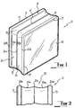
- a typical glass block 11 which is used in the present embodiment comprises two parallel rectangular side faces 13 and four adjoining end faces 15.
- the end faces 15 adjoin the corresponding edges 17 of both of the side faces 13 of the block, and furthermore adjoin the ends 19 of each other, contiguously, to form a continuous circumferential edge 21 around the block.
- the profile of the circumferential edge 21 is more clearly shown in figure 2 of the drawings and generally comprises an inner substantially concave portion 21a, a pair of outer cusps 21b and a central inner cusp 21c.
- the outer extremities of the outer cusps 21b are defined by the corresponding edges 17 of each of the side faces 13 and form a planar land along the opposing sides of each end face 15, substantially orthogonal to the outer surface of the side faces 13.
- the central inner cusp 21c is formed intermediate the outer cusps 21b and extends continuously along the circumferential edge 21 of the block, dividing the concave portion 21a of each end face 15 into two.
- This complex profile results from the method of construction of a glass block, whereby the block is actually formed from two rectangular shells which are disposed so that the open ends thereof confront each other and are welded together, the inner cusp constituting the weld seam between the adjoining edges of the two shells.
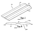
- the elongated reinforcement member 23 which is used in the present embodiment is shown in figures 7 and 8 of the drawings and essentially comprises a metal bar of aluminium or similar material.
- the bar is specially formed to adopt a cross-sectional shape which is substantially similar to the cross-sectional shape of the cavity or void formed between a pair of adjacent glass blocks, marginally spaced apart as best shown in figure 13 of the drawings.
- the reinforcement member 23 is of a flattened shape comprising a pair of thickened wings 25 which are interconnected by a central web 27.
- the web 27 is of thinner dimension than the wings 25, forming an elongated groove to be disposed within the space provided between a pair of confronting inner cusps 21c of a pair of adjacent blocks, accommodating the cusps.
- the wings 25 are generally convexly shaped to complement the shape of the concave portion 21a of a glass block on which the member reposes.
- the transverse extent of the member is commensurate to the distance between the outer cusps 21b so that the outer edges 25a of the member repose proximate to the junction between the outer cusps 21b and the respective concave portions 21a.
- the elongated reinforcement member essentially has a pair of opposing expansive sides 23a and 23b which are substantially complementary in shape to that portion of the end face 15 of a block which extends between the outer cusps thereof.
- each expansive side is substantially convex to repose between the outer cusps and the web portion 27 defines a central groove to accommodate the inner cusp
- the size of the member is marginally smaller than the resultant size of the cavity or void between the blocks to allow for expansion and contraction of the glass blocks with changes in temperature. This marginal difference in size is achieved by the arrangement of the interstitial junction spacers therewith, which now will be described.
- interstitial junction spacers are formed of polypropylene plastic material and are in two forms, one form being an intermediate junction spacer which is disposed at each internal junction of the matrix of glass blocks forming the wall, and the other form being an end junction spacer which is disposed at the end junctions between the glass blocks running along the sill and the jambs of the frame or surround within which the wall is constructed.
- the intermediate junction spacer 31 as shown in figures 3 and 4 essentially comprises a pair of intersecting spacer means which are integral with each other.
- Each spacer means has a pair of coplanar edge members 33 or 34 so that one pair of edge members 33 are formed as part of one spacer means and the other pair of edge members 34 are formed as part of the other spacer means.
- the intersection of the spacer means results in the edge members forming a cross as shown in the drawings, at each side of the spacer.
- the thickness of each edge member 33 and 34 is the same, in the present embodiment being 3mm. This thickness corresponds to the spacing required and achieved between the opposing edges 17 of adjacent blocks 11 in the manner that will be described in more detail later.
- the one spacer means comprising the edge members 33 is formed with an interconnecting web portion 35 extending between the two edge members 33.
- the web portion 35 is biased towards one side of the spacer means, its outer surface 35a being contiguous with corresponding outer surfaces 33a of the edge members 33, which are in themselves coplanar with respect to each other.
- the outer surface 35a of the web portion 35 is substantially complementary in shape to the confronting surface of the end face 15 of an adjacent glass block 11.
- the outer surface 35a is generally convex complementing the shape of the concave portions 23a of the end face of the block and being formed with a central elongate groove 37 to accommodate the inner cusp 23c of the same block.
- a plurality of outwardly projecting spacer tabs 39 are disposed at the junction between the outer surface 35a of the web portion 35 and the corresponding outer surface 33a of the edge members 33 of the one spacer means. These spacer tabs 39 are disposed one at each side of the edge members 34 of the other spacer means and project marginally inwardly to define an acute angle with the outer surface 35a of the web portion.
- the spacer tabs are sufficiently flexible and resilient by virtue of the inherent nature of the polypropylene material of which they are formed to take up any variance between the complementary shape of the outer surface of the web portion 35 and the concave portion 23a of an adjacent block.
- the inner surface 35b of the web portion 35 is recessed and is essentially of complementary shape to an expansive side 23a or 23b of the reinforcement member 23 so that the spacer 31 can engage and connect to the reinforcement member.
- the recess is terminated along its sides by opposing inner edges 33b of the edge members 33 substantially orthogonal to the corresponding outer surfaces 33a, so that the outer edges 25a of the reinforcement member 23 may situate proximate thereto.
- a plurality of outwardly projecting opposing spacer tabs 41 are angularly disposed along the inner edge 33b of each of the edge members 33 at their respective junction with the opposite outer surface 33c to the corresponding outer surface 33a. These opposing spacer tabs 41 project marginally angularly inwardly over the inner recessed surface 35b of the web portion 35, so as to define an obtuse angle with the adjacent opposite outer surface 33c of the respective edge members.
- the opposing spacer tabs 41 are disposed one to each side of the other edge member 34 and function not only to take up any variance between the complementary shape of the exposed expansive side of the reinforcement member 23, when disposed within the confines of the inner recessed surface 35b of the web portion, and the confronting concave portion 23a of an adjacent block, but also to partly retain the reinforcement member in this confined position.
- a pair of retentioning tabs 42 are provided one along each inner edge of the edge members 34 proximate to the junction with the inner edge 33b of the corresponding edge member 33.
- the retentioning tabs 42 have an outer tapered surface to allow the outer edges of the reinforcement member 23 to slide therealong when positioning the same, and an overhanging surface substantially parallel to the inner surface 35a of the web portion to retain the reinforcement in position once it engages the recess beneath the overhanging surface. Accordingly, the retentioning tabs 42 constitute the principal means by which the reinforcement member 23 is retained within the confines of the inner recessed surface 35b of the web portion 35.
- both the opposing spacer tabs 41 and the retentioning tabs 42 are sufficiently resilient to allow for the reinforcement member to be clicked into place within the inner recess where it is retained in position.
- the edge members 34 of the other spacer means are tapered from each proximal end thereof adjoining the edge members 33 of the one spacer means, to the distal ends thereof. This tapering is provided to enable the spacer 31 to be used when constructing a curved wall, whereby the one spacer means will be disposed vertically and the other spacer means disposed horizontally. In this way, the tapering of the edge members 34 takes up the curvature of the horizontal joints, which curvature is achieved by adjacent blocks being marginally angularly offset to each other about a vertical axis. Accordingly, the outer surface 34a of the edge members 34 will not project beyond the joint which would otherwise occur if the outer surface was not so tapered.
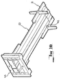
- the end junction spacer 43 is shown in figures 5 and 6 of the drawings and in principle is similar to the intermediate junction spacer 31 but includes some significant differences.
- the end junction spacer 43 comprises a pair of intersecting spacer means which are integrally formed, each comprising a pair of coplanar edge members 45 and 47, the edge members 45 forming part of one of the spacer means and the edge members 47 forming part of the other spacer means.
- the edge members 45 project from the other spacer means in only one direction, the opposing side 43a of the other spacer means being planar, as shown in figure 6 of the drawings, to facilitate engagement and affixment of the end junction spacer 43 to a planar surface which confronts the appropriate end of the block wall.
- the other spacer means is also provided with an interconnecting web portion 49, however, as opposed to the intermediate junction spacer, the web portion 49 is formed with a central aperture 51 extending between the edge members 47, so that the web portion is effectively divided into two parts 49a and 49b, respectively interconnecting the edge members 47 at their opposing ends.
- the web portion 49 is provided with a pair of holes 53 which are centrally disposed intermediate the edge members 47, one on each part 49a and 49b of the web portion. These holes 53 are provided to enable the junction spacer to be affixed to the confronting planar surface of the wall frame or the like.
- Both parts 49a and 49b of the web portion are each provided with a longitudinal rail 55 which similarly extends between the edge members 47 for strengthening purposes.
- the web portion 49 includes an end flange 57 disposed at either end thereof to project laterally from the side of each edge member 47. Accordingly, the extent of the spacer 43 between the end flanges 57 is commensurate to the distance between the opposing sides of the frame member 29 within which the corresponding end row of glass blocks will repose, in a manner which will be described in more detail later.
- the edge members 47 of the other spacer means are formed with a pair of opposing transverse grooves 59 which are disposed at the junction with the edge members 45 of the one spacer means.
- the longitudinal extent of each of the grooves 59 is respectively disposed in parallel alignment with each edge member 45 along the inner side of the edge members 47.
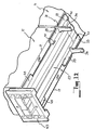
- the grooves 59 are particularly sized and shaped to retainedly accommodate the opposing edges 25a of the elongate reinforcement member 23, as best shown in figures 9 and 10 of the drawings.
- the end junction spacer 43 is fitted onto the end of a reinforcement member 25 whereby the reinforcement member may project through the central aperture 51 of the web portion 49 if necessary with the edge members 45 being disposed and projecting outwardly from the outer edges 25a of the member to still provide the requisite spacing between adjacent blocks which are situated on either side of the edge members 45.
- edge members 47 still provide a spacing function, but instead of them defining the spacing between adjacent glass blocks, as is the case with both spacer means of the intermediate junction spacer, they define the spacing between the outer face of the end blocks and the wall frame or surround confronting the ends of the glass block.
- the glass blocks 11 are laid within a rectangular frame 29, as best shown in figure 14 of the drawings.
- the present embodiment describes the use of a rectangular frame 29, the invention is not so limited and accordingly, finds equal utility where a glass block wall is desired to be constructed directly within a window or wall surround or the like, whereby the rectangular frame 29 is dispensed within entirely and the glass blocks are required to abut directly to the brickwork or other member forming the surround.
- the end junction spacers 43 may be affixed directly to the outer surface of the confronting brickwork or the like by the use of fixing screws which are mounted through the holes 53 to securely position the end junction spacer and to provide a guide for the subsequent positioning of the blocks.
- the frame 29 is used and essentially comprises a head member, (not shown) which is disposed along the top of the glass wall to be constructed, a sill member 29a which is disposed along the bottom of the glass wall to be constructed, and a pair of jambs 29b which are disposed at either end of the glass wall to be constructed to define its sides.
- the frame effectively forms a U-shaped channel and the distance between the opposing jambs and the opposing head and sill members is predetermined to allow for the exact number of glass blocks to form a rectangular matrix within the frame 29, taking into account the prescribed spacing therebetween, which in the present embodiment is 3mm.
- a strip of polystyrene foam 61 conforming to the spacing between the sides of the frame 29 is disposed within the channel members of each jamb member 29b.
- one of the end junction spacers 23 is taken and modified to form a corner spacer.
- the other spacer means has one end of it removed, by simply sawing through it with a hacksaw or the like. More particularly, the edge members 47 are transversely cut a prescribed distance from the junction with the edge members 45 removing one of the interconnecting web portion 49 from the spacer. Consequently, the modified spacer will have a pair of shortened legs formed by the remainder of the edge members 47 at one side of the other spacing member, of a length commensurate to the height of the edge members 47.
- This modified spacer is then disposed within the corner of the frame so that the planar side 43a of the spacer sits upon the inner web of the sill member 29a and the shortened legs of the other spacer means abut up against the outer surface of the polystyrene 61 on the jamb member 29b.
- the distance between the end flanges 57 is commensurate to the distance between the sides of the frame, and consequently, the modified spacer will sit precisely within the confines of the channel of the sill.
- a complete end junction spacer 43 is similarly disposed along the web of the sill, a distance approximating the size of one side of a glass block.
- the edge members 45 will project upwardly and the edge members 47 will extend in parallel relationship with the sides of the sill to provide a base on which the outer cusps of the glass block may repose.
- a glass block is then positioned so that the respective edge members 45 and 47 support the block along its corresponding outer cusps 23b at each corner of the block.
- edge members 47 are of greater height and hence thickness than the edge members 45 due to the increased loading of the block thereon, and the need to space the bottom of the block from the inner web of the sill at a distance greater than the 3mm adopted for the remaining spacing.
- the distance between the outer sides of the opposing edge members 45 and 47 is marginally less than the transverse extent of a block, but greater than the overall concave extent of the end face of the block, so that the end members can support the block adequately along its outer cusps.
- a sufficient recess is provided along the joint where the spacers are disposed to allow for the silicone binder to be caulked into the recess in the known manner.
- the unit as shown in part in figures 9 and 10 is assembled and positioned along the top of the glass blocks 11 so that the planar surface 43a of the end junction spacers engage the respective strips of polystyrene 61 and the edge members 47 are slid along the outer cusps of the end glass blocks, at the same time as the edge members 34 of the intermediate junction spacers are aligned and positioned between the confronting vertical outer cusps of adjacent blocks to provide the spacing for the vertical joints.
- the complementary shape of the spacers and the reinforcement member allow the assembled unit to position itself along the composite upper circumferential edge formed by the glass blocks, supporting and in turn accurately positioning the glass blocks themselves to allow the next row of blocks to be laid thereon.
- the next row of glass blocks is laid by simply inserting one block at a time between the exposed upwardly projecting edge members 34 of the intermediate junction spacers and the upwardly projecting'edge members 47 of the end junction spacers 43 of the positioned unit. This method is then repeated for subsequent rows until the top row is laid, whereby the sequence needs to be modified by making the last glass block to be erected, one of the blocks intermediate the corner blocks. In addition, positioning spacers and the reinforcement member along the very top of the top row is dispensed with to facilitate locating the glass blocks within the head of the frame.
- the silicone binder can be inserted by caulking along the grooves formed by the spacing between the blocks which results from the positioning of the various spacers.
- the spacers have utility not only in the construction of planar faced walls, but also can be used in the construction of curved walls.
- the reinforcement members will be disposed within the vertical joints so that with respect to the intermediate junction spacers, these will be disposed with the one spacer means thereof extending vertically to accommodate the reinforcement members and the other spacer means disposed horizontally.
- the tapered outer surface 34a of each edge member 34, and in the case of the edge junction spacers, the edge members 45 enable a block to be marginally offset angularly to achieve the curvature, without the outer surface of the edge members projecting outwardly beyond the confines of the joint.
- an intermediate junction spacer can be conceived using some of the features of the end junction spacer described, whereby the interconnecting web portion is provided with a central aperture through which a reinforcement member may pass, the web being substantially orthogonal to the reinforcement member.
Landscapes
- Engineering & Computer Science (AREA)
- Architecture (AREA)
- Civil Engineering (AREA)
- Structural Engineering (AREA)
- Finishing Walls (AREA)
- Securing Of Glass Panes Or The Like (AREA)
- Lining And Supports For Tunnels (AREA)
- Revetment (AREA)
- Reinforcement Elements For Buildings (AREA)
- Building Environments (AREA)
- Joining Of Building Structures In Genera (AREA)
- Filling Or Discharging Of Gas Storage Vessels (AREA)
- Supports For Pipes And Cables (AREA)
- Forms Removed On Construction Sites Or Auxiliary Members Thereof (AREA)
- Storage Of Harvested Produce (AREA)
Applications Claiming Priority (4)
| Application Number | Priority Date | Filing Date | Title |
|---|---|---|---|
| AUPM3206/93 | 1993-12-31 | ||
| AUPM320693 | 1993-12-31 | ||
| AUPM3206A AUPM320693A0 (en) | 1993-12-31 | 1993-12-31 | A block wall construction system and components thereof |
| PCT/AU1994/000788 WO1995018278A1 (en) | 1993-12-31 | 1994-12-22 | A block wall construction system and components thereof |
Publications (3)
| Publication Number | Publication Date |
|---|---|
| EP0737264A1 EP0737264A1 (en) | 1996-10-16 |
| EP0737264A4 EP0737264A4 (en) | 1997-04-02 |
| EP0737264B1 true EP0737264B1 (en) | 2003-05-02 |
Family
ID=3777830
Family Applications (1)
| Application Number | Title | Priority Date | Filing Date |
|---|---|---|---|
| EP95904366A Expired - Lifetime EP0737264B1 (en) | 1993-12-31 | 1994-12-22 | A block wall construction system and components thereof |
Country Status (19)
| Country | Link |
|---|---|
| US (1) | US5907937A (enExample) |
| EP (1) | EP0737264B1 (enExample) |
| KR (1) | KR100241591B1 (enExample) |
| CN (2) | CN1143400A (enExample) |
| AT (1) | ATE239153T1 (enExample) |
| AU (1) | AUPM320693A0 (enExample) |
| CA (1) | CA2180129C (enExample) |
| CZ (1) | CZ292496B6 (enExample) |
| DE (1) | DE69432603T2 (enExample) |
| EG (1) | EG20463A (enExample) |
| ES (1) | ES2201095T3 (enExample) |
| IN (1) | IN192353B (enExample) |
| JO (1) | JO1845B1 (enExample) |
| MY (1) | MY124438A (enExample) |
| NZ (1) | NZ277736A (enExample) |
| SA (1) | SA95160049B1 (enExample) |
| SG (1) | SG46418A1 (enExample) |
| TW (1) | TW274109B (enExample) |
| WO (1) | WO1995018278A1 (enExample) |
Cited By (1)
| Publication number | Priority date | Publication date | Assignee | Title |
|---|---|---|---|---|
| CN103912077A (zh) * | 2014-04-08 | 2014-07-09 | 深圳市岭巅科技发展有限公司 | 隔墙装置 |
Families Citing this family (30)
| Publication number | Priority date | Publication date | Assignee | Title |
|---|---|---|---|---|
| NO20003213L (no) * | 2000-06-21 | 2001-12-24 | Jon Cato Olsen | Fremgangsmåte og element for bygging med glassbygger-sten |
| US6684929B2 (en) | 2002-02-15 | 2004-02-03 | Steelcase Development Corporation | Panel system |
| US7509780B2 (en) * | 2002-10-09 | 2009-03-31 | Athanasios Leontaridis | Joint for the angular connection of door window profile frames and the like |
| US6922961B2 (en) * | 2002-10-22 | 2005-08-02 | Seattle Glass Block | Vertical and horizontal spacers to form curved glass block walls |
| US6823634B2 (en) * | 2002-11-07 | 2004-11-30 | Seattle Glass Block | Horizontal spacer to form angled glass block walls |
| US20040088936A1 (en) * | 2002-11-07 | 2004-05-13 | Brian Wright | Spacer system for glass block walls |
| US20060010810A1 (en) * | 2002-12-18 | 2006-01-19 | Arkadiusz Muszynski | Wall construction using hollow glass building elements |
| US6840019B2 (en) * | 2003-03-19 | 2005-01-11 | Thomas J. Berg | Method and apparatus to achieve consistent spacing between layers of modular construction |
| GB0306423D0 (en) * | 2003-03-20 | 2003-04-23 | Proffer Glass Engros As | System for building with glass blocks |
| USD494042S1 (en) * | 2003-04-30 | 2004-08-10 | Seattle Glass Block | Glass block spacer |
| US20050241268A1 (en) * | 2004-04-21 | 2005-11-03 | Horace Tjakra | Rigid spacer for glass block window assemblies |
| US7555872B1 (en) * | 2005-01-04 | 2009-07-07 | Jeffrey Beach | Spacer for aligning concrete blocks |
| US20060272250A1 (en) * | 2005-05-09 | 2006-12-07 | John Friesen | Glass block panel anchor and reinforcing system |
| US20070032138A1 (en) * | 2005-08-05 | 2007-02-08 | Armando Quinones | Apparatus and Method for Stabilizing, Strengthening, and Reinforcing Block/Brick (CMU) Wall Construction |
| US7587870B2 (en) * | 2006-02-21 | 2009-09-15 | Extech/Exterior Technologies, Inc. | Grid system for mounting building blocks |
| GB2441604A (en) * | 2006-08-05 | 2008-03-12 | Terence David Wall | A spacer for laying bricks and blocks |
| CA2570653A1 (en) * | 2006-12-08 | 2008-06-08 | Global Plastics | Spacer assembly for glass blocks |
| US7870696B2 (en) * | 2007-08-28 | 2011-01-18 | Chia-Yen Lin | Panel assembly for decoration glass |
| US20110076447A1 (en) * | 2007-08-28 | 2011-03-31 | Chia-Yen Lin | Panel assembly for decoration |
| US20090255448A1 (en) * | 2008-04-10 | 2009-10-15 | Loomis Nicholas T | Blast resistant glass block panel |
| US8297021B2 (en) * | 2009-01-23 | 2012-10-30 | Armando Quinones | System for constructing and reinforcing block wall construction |
| WO2010089431A1 (es) * | 2009-02-05 | 2010-08-12 | Vetroclick, S.L. | Dispositivo para el montaje de ladrillos de vidrio |
| IT1397562B1 (it) * | 2009-12-21 | 2013-01-16 | Giotto S R L | Perfezionamenti a dispositivo di giunzione reciproca di vetromattoni. |
| US20120073230A1 (en) * | 2010-09-24 | 2012-03-29 | Fmi Products, Llc | Pre-engineered brick panel and methods of making and installing same |
| US9086268B2 (en) * | 2013-10-02 | 2015-07-21 | Jonathan E Jones | Concrete block spacer system |
| CN106812280B (zh) * | 2016-12-29 | 2022-08-16 | 佛山市盛画世纪建材有限公司 | 一种适用于砖板间拼接安装的u型构件 |
| CN106522413B (zh) * | 2016-12-29 | 2019-01-29 | 佛山市盛画世纪建材有限公司 | 建墙体系中最后一块积木砖的安装方式 |
| US9903111B1 (en) * | 2017-02-14 | 2018-02-27 | Orial Nir | Construction assembly and method for laying blocks |
| KR102633420B1 (ko) * | 2023-01-31 | 2024-02-06 | 한상홍 | 유리블럭 시공부재 |
| KR102816033B1 (ko) * | 2024-08-26 | 2025-06-04 | 김종대 | 시공 편의성을 높인 유리블록용 셀프 시공 키트 |
Family Cites Families (21)
| Publication number | Priority date | Publication date | Assignee | Title |
|---|---|---|---|---|
| US2239637A (en) * | 1940-04-30 | 1941-04-22 | John H Zesewitz | Spindle seal for fluid pressure motors |
| US2314238A (en) * | 1940-05-03 | 1943-03-16 | Julius J Ohlis | Glass panel construction |
| US4019302A (en) * | 1973-04-03 | 1977-04-26 | Meyer Leon J | Metal flange web connection |
| AT343876B (de) * | 1975-12-15 | 1978-06-26 | Schoeller Fa Geb | Verlorener distanzhalter fur mauersteine, insbesondere glasziegel |
| FR2542353B1 (fr) * | 1983-03-09 | 1985-10-25 | Manon Gerard | Element de verre en particulier brique ou pave de verre |
| AU3127984A (en) * | 1983-08-23 | 1985-02-28 | Arthur Kenneth Gallagher | Brick laying apparatus |
| US4570406A (en) * | 1983-12-12 | 1986-02-18 | Acorn Building Components, Inc. | Screen frame corner connector key |
| AU7003387A (en) * | 1986-03-13 | 1987-09-17 | Douglas Harvey | Spacer for brick courses |
| US4774793A (en) * | 1986-03-24 | 1988-10-04 | Emil Mayer | Glass block panel construction and device for use in same |
| JPS62244935A (ja) * | 1986-04-17 | 1987-10-26 | 千葉 春海 | 硝子ブロツク壁の組立工法 |
| DE3806711A1 (de) * | 1987-05-27 | 1988-12-15 | Willi Schwarz | Vorrichtung zum errichten einer wand, insbesondere aus glasbausteinen |
| DE8707630U1 (de) * | 1987-05-27 | 1987-07-23 | Schwarz, Willi, 2300 Kiel | Montagestück zum Verlegen von Glasbausteinen |
| US4793104A (en) * | 1988-06-15 | 1988-12-27 | Delberg, Inc. | Guide for laying glass blocks |
| DE8902153U1 (de) * | 1989-02-23 | 1989-05-03 | Schwarz, Willi, 2300 Kiel | Verlegestück für eine Vorrichtung zum Errichten einer Wand aus Glasbausteinen |
| FR2645195A1 (fr) * | 1989-03-29 | 1990-10-05 | Riboh Samuel | Paroi translucide en carreau de verre |
| DE8906727U1 (de) * | 1989-06-01 | 1989-07-27 | Siemens AG, 1000 Berlin und 8000 München | Vorrichtung zum Antrieb eines Druckerwagens entlang einer Schreibwalze in einer Druckeinrichtung |
| US4986048A (en) * | 1990-01-11 | 1991-01-22 | Pittsburgh Corning Corporation | Method and apparatus for erecting a glass block wall |
| US5031372A (en) * | 1990-09-04 | 1991-07-16 | Mccluer Steve | Modular frame assembly for mounting glass blocks |
| US5259161A (en) * | 1991-06-03 | 1993-11-09 | Carter Frank P | Vertical and horizontal reinforcement and spacing guide for panels constructed of blocks |
| US5224314A (en) * | 1992-02-18 | 1993-07-06 | Chen Syu A | Wasted spacer member for wall elements |
| US5485702A (en) * | 1994-03-25 | 1996-01-23 | Glenn Sholton | Mortarless glass block assembly |
-
1993
- 1993-12-31 AU AUPM3206A patent/AUPM320693A0/en not_active Abandoned
-
1994
- 1994-12-22 WO PCT/AU1994/000788 patent/WO1995018278A1/en not_active Ceased
- 1994-12-22 KR KR1019960703620A patent/KR100241591B1/ko not_active Expired - Fee Related
- 1994-12-22 CN CN94195044.1A patent/CN1143400A/zh active Pending
- 1994-12-22 EP EP95904366A patent/EP0737264B1/en not_active Expired - Lifetime
- 1994-12-22 DE DE69432603T patent/DE69432603T2/de not_active Expired - Lifetime
- 1994-12-22 ES ES95904366T patent/ES2201095T3/es not_active Expired - Lifetime
- 1994-12-22 AT AT95904366T patent/ATE239153T1/de not_active IP Right Cessation
- 1994-12-22 SG SG1996004524A patent/SG46418A1/en unknown
- 1994-12-22 US US08/669,356 patent/US5907937A/en not_active Expired - Fee Related
- 1994-12-22 CA CA002180129A patent/CA2180129C/en not_active Expired - Fee Related
- 1994-12-22 NZ NZ277736A patent/NZ277736A/en not_active IP Right Cessation
- 1994-12-22 CZ CZ19961925A patent/CZ292496B6/cs not_active IP Right Cessation
- 1994-12-23 IN IN1682DE1994 patent/IN192353B/en unknown
- 1994-12-24 TW TW083112178A patent/TW274109B/zh active
- 1994-12-29 EG EG83394A patent/EG20463A/xx active
- 1994-12-30 MY MYPI94003569A patent/MY124438A/en unknown
- 1994-12-31 JO JO19941845A patent/JO1845B1/en active
-
1995
- 1995-06-18 SA SA95160049A patent/SA95160049B1/ar unknown
-
2001
- 2001-06-29 CN CN01117561.3A patent/CN1128909C/zh not_active Expired - Fee Related
Cited By (1)
| Publication number | Priority date | Publication date | Assignee | Title |
|---|---|---|---|---|
| CN103912077A (zh) * | 2014-04-08 | 2014-07-09 | 深圳市岭巅科技发展有限公司 | 隔墙装置 |
Also Published As
| Publication number | Publication date |
|---|---|
| WO1995018278A1 (en) | 1995-07-06 |
| EP0737264A4 (en) | 1997-04-02 |
| JO1845B1 (en) | 1995-07-05 |
| DE69432603D1 (de) | 2003-06-05 |
| CZ192596A3 (en) | 1997-02-12 |
| EG20463A (en) | 1999-05-31 |
| AUPM320693A0 (en) | 1994-01-27 |
| SA95160049B1 (ar) | 2006-11-04 |
| MY124438A (en) | 2006-06-30 |
| CA2180129C (en) | 2005-03-22 |
| CA2180129A1 (en) | 1995-07-06 |
| MX9500042A (es) | 1997-10-31 |
| ATE239153T1 (de) | 2003-05-15 |
| SG46418A1 (en) | 1998-02-20 |
| DE69432603T2 (de) | 2004-05-13 |
| NZ277736A (en) | 1996-11-26 |
| CZ292496B6 (cs) | 2003-10-15 |
| CN1128909C (zh) | 2003-11-26 |
| KR100241591B1 (ko) | 2000-02-01 |
| US5907937A (en) | 1999-06-01 |
| EP0737264A1 (en) | 1996-10-16 |
| ES2201095T3 (es) | 2004-03-16 |
| CN1356443A (zh) | 2002-07-03 |
| CN1143400A (zh) | 1997-02-19 |
| IN192353B (enExample) | 2004-04-10 |
| TW274109B (enExample) | 1996-04-11 |
Similar Documents
| Publication | Publication Date | Title |
|---|---|---|
| EP0737264B1 (en) | A block wall construction system and components thereof | |
| CA2033839C (en) | Method and apparatus for erecting a glass block wall | |
| US5259161A (en) | Vertical and horizontal reinforcement and spacing guide for panels constructed of blocks | |
| JP2649586B2 (ja) | 集成用ブロック | |
| US5704180A (en) | Insulating concrete form utilizing interlocking foam panels | |
| CA1092846A (en) | Foamed plastic concrete form and connectors therefor | |
| RU2347869C2 (ru) | Система образования изолированной бетонной стены и соединительные перемычки на шарнирах | |
| CA2191914C (en) | Insulated concrete form | |
| US5181362A (en) | Interlocking building blocks | |
| US4604843A (en) | Lost-form concrete falsework | |
| EP0713553B1 (en) | A glass brick wall | |
| US20120311949A1 (en) | Thermal insulated building wall construction method | |
| US8171693B2 (en) | Interlocking masonry blocks | |
| US5218806A (en) | Glass-block panels and method of fabrication thereof | |
| CA1177661A (en) | Method and apparatus for erecting walls made of glass bricks and at least one joint-mortar, together with a joint lining and, if nesessary, reinforcing elements | |
| US4580373A (en) | Building element and roof structure comprising a plurality of such elements | |
| US6293068B1 (en) | Foam panel and channel concrete form system | |
| US2088625A (en) | Building brick | |
| KR100395854B1 (ko) | 흙구조물의외장재 | |
| GB2092201A (en) | Building block | |
| AU680088B2 (en) | A block wall construction system and components thereof | |
| US2140998A (en) | Wall or the like | |
| GB2285072A (en) | Cavity closer | |
| MXPA95000042A (en) | Wall construction system based on blocks and their components | |
| US4056909A (en) | Surface waterstops |
Legal Events
| Date | Code | Title | Description |
|---|---|---|---|
| PUAI | Public reference made under article 153(3) epc to a published international application that has entered the european phase |
Free format text: ORIGINAL CODE: 0009012 |
|
| 17P | Request for examination filed |
Effective date: 19960629 |
|
| AK | Designated contracting states |
Kind code of ref document: A1 Designated state(s): AT BE CH DE DK ES FR GB GR IE IT LI LU MC NL PT SE |
|
| A4 | Supplementary search report drawn up and despatched |
Effective date: 19970213 |
|
| AK | Designated contracting states |
Kind code of ref document: A4 Designated state(s): AT BE CH DE DK ES FR GB GR IE IT LI LU MC NL PT SE |
|
| 17Q | First examination report despatched |
Effective date: 19990716 |
|
| GRAH | Despatch of communication of intention to grant a patent |
Free format text: ORIGINAL CODE: EPIDOS IGRA |
|
| GRAH | Despatch of communication of intention to grant a patent |
Free format text: ORIGINAL CODE: EPIDOS IGRA |
|
| GRAH | Despatch of communication of intention to grant a patent |
Free format text: ORIGINAL CODE: EPIDOS IGRA |
|
| GRAA | (expected) grant |
Free format text: ORIGINAL CODE: 0009210 |
|
| AK | Designated contracting states |
Designated state(s): AT BE CH DE DK ES FR GB GR IE IT LI LU MC NL PT SE |
|
| PG25 | Lapsed in a contracting state [announced via postgrant information from national office to epo] |
Ref country code: NL Free format text: LAPSE BECAUSE OF FAILURE TO SUBMIT A TRANSLATION OF THE DESCRIPTION OR TO PAY THE FEE WITHIN THE PRESCRIBED TIME-LIMIT Effective date: 20030502 Ref country code: LI Free format text: LAPSE BECAUSE OF FAILURE TO SUBMIT A TRANSLATION OF THE DESCRIPTION OR TO PAY THE FEE WITHIN THE PRESCRIBED TIME-LIMIT Effective date: 20030502 Ref country code: CH Free format text: LAPSE BECAUSE OF FAILURE TO SUBMIT A TRANSLATION OF THE DESCRIPTION OR TO PAY THE FEE WITHIN THE PRESCRIBED TIME-LIMIT Effective date: 20030502 Ref country code: AT Free format text: LAPSE BECAUSE OF FAILURE TO SUBMIT A TRANSLATION OF THE DESCRIPTION OR TO PAY THE FEE WITHIN THE PRESCRIBED TIME-LIMIT Effective date: 20030502 |
|
| REG | Reference to a national code |
Ref country code: GB Ref legal event code: FG4D |
|
| REG | Reference to a national code |
Ref country code: CH Ref legal event code: EP |
|
| BECA | Be: change of holder's address |
Owner name: 19 EXCHANGE ROAD, MALAGA, WESTERN AUSTRALIA 6090 Effective date: 20030502 Owner name: *GLASS BLOCK CONSTRUCTIONS (AUST) PTY LTD62 MCCOY Effective date: 20030502 Owner name: W. *LOFTUS & CO. PTY LTD Effective date: 20030502 |
|
| REF | Corresponds to: |
Ref document number: 69432603 Country of ref document: DE Date of ref document: 20030605 Kind code of ref document: P |
|
| REG | Reference to a national code |
Ref country code: IE Ref legal event code: FG4D |
|
| PG25 | Lapsed in a contracting state [announced via postgrant information from national office to epo] |
Ref country code: GR Free format text: LAPSE BECAUSE OF FAILURE TO SUBMIT A TRANSLATION OF THE DESCRIPTION OR TO PAY THE FEE WITHIN THE PRESCRIBED TIME-LIMIT Effective date: 20030802 Ref country code: DK Free format text: LAPSE BECAUSE OF FAILURE TO SUBMIT A TRANSLATION OF THE DESCRIPTION OR TO PAY THE FEE WITHIN THE PRESCRIBED TIME-LIMIT Effective date: 20030802 |
|
| PG25 | Lapsed in a contracting state [announced via postgrant information from national office to epo] |
Ref country code: PT Free format text: LAPSE BECAUSE OF FAILURE TO SUBMIT A TRANSLATION OF THE DESCRIPTION OR TO PAY THE FEE WITHIN THE PRESCRIBED TIME-LIMIT Effective date: 20030804 |
|
| REG | Reference to a national code |
Ref country code: SE Ref legal event code: TRGR |
|
| RAP2 | Party data changed (patent owner data changed or rights of a patent transferred) |
Owner name: GLASS BLOCK CONSTRUCTIONS (AUST) PTY LTD Owner name: W. LOFTUS & CO. PTY LTD |
|
| NLV1 | Nl: lapsed or annulled due to failure to fulfill the requirements of art. 29p and 29m of the patents act | ||
| REG | Reference to a national code |
Ref country code: CH Ref legal event code: PL |
|
| PG25 | Lapsed in a contracting state [announced via postgrant information from national office to epo] |
Ref country code: LU Free format text: LAPSE BECAUSE OF NON-PAYMENT OF DUE FEES Effective date: 20031222 Ref country code: IE Free format text: LAPSE BECAUSE OF NON-PAYMENT OF DUE FEES Effective date: 20031222 |
|
| PG25 | Lapsed in a contracting state [announced via postgrant information from national office to epo] |
Ref country code: MC Free format text: LAPSE BECAUSE OF NON-PAYMENT OF DUE FEES Effective date: 20031231 |
|
| PLBE | No opposition filed within time limit |
Free format text: ORIGINAL CODE: 0009261 |
|
| STAA | Information on the status of an ep patent application or granted ep patent |
Free format text: STATUS: NO OPPOSITION FILED WITHIN TIME LIMIT |
|
| ET | Fr: translation filed | ||
| REG | Reference to a national code |
Ref country code: ES Ref legal event code: FG2A Ref document number: 2201095 Country of ref document: ES Kind code of ref document: T3 |
|
| 26N | No opposition filed |
Effective date: 20040203 |
|
| REG | Reference to a national code |
Ref country code: IE Ref legal event code: MM4A |
|
| REG | Reference to a national code |
Ref country code: HK Ref legal event code: WD Ref document number: 1014567 Country of ref document: HK |
|
| PGFP | Annual fee paid to national office [announced via postgrant information from national office to epo] |
Ref country code: SE Payment date: 20091218 Year of fee payment: 16 Ref country code: ES Payment date: 20091224 Year of fee payment: 16 |
|
| PGFP | Annual fee paid to national office [announced via postgrant information from national office to epo] |
Ref country code: GB Payment date: 20091221 Year of fee payment: 16 |
|
| PGFP | Annual fee paid to national office [announced via postgrant information from national office to epo] |
Ref country code: DE Payment date: 20091222 Year of fee payment: 16 Ref country code: BE Payment date: 20091223 Year of fee payment: 16 |
|
| PGFP | Annual fee paid to national office [announced via postgrant information from national office to epo] |
Ref country code: FR Payment date: 20110314 Year of fee payment: 17 Ref country code: IT Payment date: 20101230 Year of fee payment: 17 |
|
| BERE | Be: lapsed |
Owner name: *GLASS BLOCK CONSTRUCTIONS (AUST) PTY LTD Effective date: 20101231 Owner name: W. *LOFTUS & CO. PTY LTD Effective date: 20101231 |
|
| GBPC | Gb: european patent ceased through non-payment of renewal fee |
Effective date: 20101222 |
|
| REG | Reference to a national code |
Ref country code: SE Ref legal event code: EUG |
|
| PG25 | Lapsed in a contracting state [announced via postgrant information from national office to epo] |
Ref country code: BE Free format text: LAPSE BECAUSE OF NON-PAYMENT OF DUE FEES Effective date: 20101231 Ref country code: SE Free format text: LAPSE BECAUSE OF NON-PAYMENT OF DUE FEES Effective date: 20101223 |
|
| REG | Reference to a national code |
Ref country code: DE Ref legal event code: R119 Ref document number: 69432603 Country of ref document: DE Effective date: 20110701 |
|
| PG25 | Lapsed in a contracting state [announced via postgrant information from national office to epo] |
Ref country code: DE Free format text: LAPSE BECAUSE OF NON-PAYMENT OF DUE FEES Effective date: 20110701 Ref country code: GB Free format text: LAPSE BECAUSE OF NON-PAYMENT OF DUE FEES Effective date: 20101222 |
|
| REG | Reference to a national code |
Ref country code: ES Ref legal event code: FD2A Effective date: 20120206 |
|
| PG25 | Lapsed in a contracting state [announced via postgrant information from national office to epo] |
Ref country code: ES Free format text: LAPSE BECAUSE OF NON-PAYMENT OF DUE FEES Effective date: 20101223 |
|
| REG | Reference to a national code |
Ref country code: FR Ref legal event code: ST Effective date: 20120831 |
|
| PG25 | Lapsed in a contracting state [announced via postgrant information from national office to epo] |
Ref country code: IT Free format text: LAPSE BECAUSE OF NON-PAYMENT OF DUE FEES Effective date: 20111222 |
|
| PG25 | Lapsed in a contracting state [announced via postgrant information from national office to epo] |
Ref country code: FR Free format text: LAPSE BECAUSE OF NON-PAYMENT OF DUE FEES Effective date: 20120102 |