EP0736735A2 - Sicherheitswerkbank mit Armauflage - Google Patents
Sicherheitswerkbank mit Armauflage Download PDFInfo
- Publication number
- EP0736735A2 EP0736735A2 EP96102500A EP96102500A EP0736735A2 EP 0736735 A2 EP0736735 A2 EP 0736735A2 EP 96102500 A EP96102500 A EP 96102500A EP 96102500 A EP96102500 A EP 96102500A EP 0736735 A2 EP0736735 A2 EP 0736735A2
- Authority
- EP
- European Patent Office
- Prior art keywords
- ventilation openings
- safety workbench
- boundary plate
- supports
- armrest
- Prior art date
- Legal status (The legal status is an assumption and is not a legal conclusion. Google has not performed a legal analysis and makes no representation as to the accuracy of the status listed.)
- Granted
Links
- 238000009423 ventilation Methods 0.000 claims abstract description 18
- 210000000245 forearm Anatomy 0.000 description 2
- 102000006835 Lamins Human genes 0.000 description 1
- 108010047294 Lamins Proteins 0.000 description 1
- 229910000831 Steel Inorganic materials 0.000 description 1
- 210000005053 lamin Anatomy 0.000 description 1
- 239000000463 material Substances 0.000 description 1
- 230000000284 resting effect Effects 0.000 description 1
- 229910001220 stainless steel Inorganic materials 0.000 description 1
- 239000010935 stainless steel Substances 0.000 description 1
- 239000010959 steel Substances 0.000 description 1
Images

Classifications
-
- B—PERFORMING OPERATIONS; TRANSPORTING
- B25—HAND TOOLS; PORTABLE POWER-DRIVEN TOOLS; MANIPULATORS
- B25H—WORKSHOP EQUIPMENT, e.g. FOR MARKING-OUT WORK; STORAGE MEANS FOR WORKSHOPS
- B25H1/00—Work benches; Portable stands or supports for positioning portable tools or work to be operated on thereby
- B25H1/20—Work benches; Portable stands or supports for positioning portable tools or work to be operated on thereby with provision for shielding the work area
-
- B—PERFORMING OPERATIONS; TRANSPORTING
- B01—PHYSICAL OR CHEMICAL PROCESSES OR APPARATUS IN GENERAL
- B01L—CHEMICAL OR PHYSICAL LABORATORY APPARATUS FOR GENERAL USE
- B01L9/00—Supporting devices; Holding devices
- B01L9/02—Laboratory benches or tables; Fittings therefor
-
- B—PERFORMING OPERATIONS; TRANSPORTING
- B25—HAND TOOLS; PORTABLE POWER-DRIVEN TOOLS; MANIPULATORS
- B25H—WORKSHOP EQUIPMENT, e.g. FOR MARKING-OUT WORK; STORAGE MEANS FOR WORKSHOPS
- B25H1/00—Work benches; Portable stands or supports for positioning portable tools or work to be operated on thereby
- B25H1/02—Work benches; Portable stands or supports for positioning portable tools or work to be operated on thereby of table type
Definitions
- the invention relates to a safety workbench with a work opening, the lower boundary of which is formed by a boundary plate in which ventilation openings for generating a vertical air flow are arranged and with at least one armrest arranged in the lower region of the work opening.
- Safety cabinets are generally known, for example from the company brochure "Biological safety cabinets Heraeus Lamin Air HB and HBB" from Heraeus Instruments GmbH.
- Safety cabinets of this type are designed in such a way that a vertically directed air flow can be generated parallel to the working opening, which, as a kind of veil, prevents contaminated atmosphere from escaping from the working area of the safety cabinet through the working opening.
- ventilation openings are provided on the lower, essentially horizontal boundary plate of the working opening, through which an air flow directed vertically downwards is generated.
- the boundary plate can be rounded off on its outward edge facing the operator. If the boundary plate is used as an armrest in the manner shown, the ventilation openings are covered by the arms, so that a laminar air flow is prevented. This interferes with the function of this air flow. In addition, the boundary plate can be cleaned only with relatively great effort.
- GB 21 12 927 A discloses a safety workbench with an armrest arranged on the lower edge of the opening.
- the object of the present invention is to create, based on the known prior art, a safety workbench in which the armrests are easy to decontaminate and do not significantly reduce the effective cross section of the ventilation openings.
- the object for a safety workbench characterized in the introduction is achieved in that the armrest is designed as a separate component and is detachably held in the boundary plate in the ventilation openings and has a support plate and supports, the supports being held at the lower ends of the ventilation openings.
- a separate armrest can also be decontaminated separately and therefore very easily, and on the other hand, a separate armrest can be designed ergonomically, since it is not subject to the design principle of the boundary plate.
- the ventilation openings are closed in an uncontrolled manner by resting the arms on the boundary plate; with a separate armrest, the number of closed ventilation openings can be kept to a minimum.
- the supports are angled several times to form two horizontal sections, one horizontal section abutting the upper side of the boundary plate and the second horizontal section abutting the lower side of the boundary plate.
- the ventilation openings are designed as slots and that several rows of slots, each arranged parallel to one another, are arranged next to one another to form a grid.
- the slot-shaped design ensures a good fixation, since the supports within the slots can be moved in the longitudinal direction of the slots and are therefore easy to install, but there are narrow limits to the movement transverse to the slot, in particular if the width of the supports is only slightly less than is the width of the slots.
- the working opening of the safety workbench is delimited at its lower end by a limiting plate 1.
- the boundary plate 1 is arranged essentially horizontally and evenly and has slot-shaped ventilation openings 2 through which an air flow directed vertically upwards is guided.
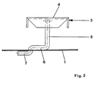
- the armrest 3 has a support plate 4 which is arranged approximately 50 mm above the boundary plate 1 and which is held with supports 5 in the boundary plate 1.
- the supports 5 point vertically downwards to the boundary plate 1 and are then angled to a horizontal section 6 which rests on the boundary plate 1. At the end of this first horizontal section 6, the supports 5 are angled downwards through a respective ventilation opening 2 and form below the limiting plate 1 a second horizontal section 7 which bears against the limiting plate 1 from below.
- the two horizontal sections 6; 7 can be arranged in a step-like manner, as shown in FIG. 2, or also in a U-shape. However, a U-shaped arrangement is less stable.
- the armrest 3 is made of stainless steel and is therefore easily autoclavable.
- the supports 5 are made of round steel and have a diameter which is only slightly smaller than the width of the slit-shaped ventilation openings 2, so that the armrest 3 is also well locked in the lateral direction.
- the supports can accordingly also be formed from flat material.
Landscapes
- Engineering & Computer Science (AREA)
- Mechanical Engineering (AREA)
- Health & Medical Sciences (AREA)
- Clinical Laboratory Science (AREA)
- Chemical & Material Sciences (AREA)
- Chemical Kinetics & Catalysis (AREA)
- Ladders (AREA)
- Apparatus Associated With Microorganisms And Enzymes (AREA)
- Ventilation (AREA)
- Forklifts And Lifting Vehicles (AREA)
Abstract
Description
- Die Erfindung betrifft eine Sicherheitswerkbank mit einer Arbeitsöffnung, deren untere Begrenzung durch eine Begrenzungsplatte gebildet ist, in der Lüftungsöffnungen zur Erzeugung eines senkrechten Luftstroms angeordnet sind und mit mindestens einer im unteren Bereich der Arbeitsöffnung angeordneten Armauflage.
- Derartige Sicherheitswerkbänke sind allgemein, beispielsweise aus dem Firmenprospekt "Biologische Sicherheitswerkbänke Heraeus Lamin Air HB und HBB" der Heraeus Instruments GmbH bekannt. Sicherheitswerkbänke dieser Art sind so ausgebildet, daß parallel zur Arbeitsöffnung ein senkrecht gerichteter Luftstrom erzeugt werden kann, der als eine Art Schleier verhindert, daß kontaminierte Atmosphäre aus dem Arbeitsraum der Sicherheitswerkbank durch die Arbeitsöffnung nach außen gelangt. Dazu sind an der unteren, im wesentlichen waagerechten Begrenzungsplatte der Arbeitsöffnung Lüftungsöffnungen vorgesehen, durch die ein senkrecht nach unten gerichteter Luftstrom erzeugt wird.
- Häufig ist es erforderlich, daß über einen längeren Zeitraum hinweg in der Sicherheitswerkbank manuell gearbeitet wird. Die an der Sicherheitswerkbank arbeitende Person ist dabei einer relativ hohen körperlichen Belastung der Arme ausgesetzt. Um eine Ermüdung, insbesondere der Unterarme und der Hände zu vermeiden, wird daher die untere Begrenzungsplatte als Auflagefläche für die Unterarme benutzt. Dazu kann die Begrenzungsplatte an ihrer nach außen, zum Bediener hin gewandten Kante abgerundet sein. Wird die Begrenzungsplatte in der dargestellten Art als Armauflage benutzt, werden die Lüftungsöffnungen durch die Arme abgedeckt, so daß eine laminare Luftströmung verhindert wird. Dadurch wird die Funktion dieser Luftströmung gestört. Außerdem ist die Begrenzungsplatte nur relativ aufwendig reinigbar.
- Aus GB 21 12 927 A ist eine Sicherheitswerkbank mit an der unteren Kante der Öffnung angeordneter Armauflage bekannt.
- Aufgabe der vorliegenden Erfindung ist es, ausgehend von dem bekannten Stand der Technik eine Sicherheitswerkbank zu schaffen, bei der die Armauflagen leicht zu dekontaminieren sind und den effektiven Querschnitt der Lüftungsöffnungen nicht wesentlich verringern.
- Erfindungsgemäß wird die Aufgabe für eine eingangs charakterisierte Sicherheitswerkbank dadurch gelöst, daß die Armauflage als separates Bauteil ausgebildet und lösbar in der Begrenzungsplatte in den Lüftungsöffnungen gehaltert ist und eine Auflageplatte und Stützen aufweist, wobei die Stützen an ihren unteren Enden an den Lüftungsöffnungen gehaltert sind. Eine separate Armauflage kann zum einen auch separat und damit sehr einfach dekontaminiert werden, zum anderen kann eine separate Armauflage ergonomisch günstig gestaltet werden, da sie nicht dem Konstruktionsprinzip der Begrenzungsplatte unterliegt. Des weiteren wird vermieden, daß durch Auflage der Arme auf der Begrenzungsplatte die Lüftungsöffnungen unkontrolliert verschlossen werden; bei einer separaten Armauflage kann die Zahl der verschlossenen Lüftungsöffnungen auf ein Minimum begrenzt werden.
- Zweckmäßig für eine einfache Handhabung ist es, daß zwei separate Armauflagen vorgesehen sind, so daß die für jeden Arm benötigte Armauflage individuell angeordnet werden kann. Insbesondere ist es vorteilhaft, daß die Stützen unter Bildung zweier waagerechter Abschnitte mehrfach abgewinkelt sind, wobei ein waagerechter Abschnitt an der Oberseite der Begrenzungsplatte und der zweite waagerechte Abschnitt an der Unterseite der Begrenzungsplatte anliegt.
- Vorteilhaft ist es auch, daß die Lüftungsöffnungen als Schlitze ausgebildet sind und daß mehrere Reihen von jeweils parallel zueinander angeordneten Schlitzen unter Bildung eines Rasters nebeneinander angeordnet sind. Eine derartige Anordnung ermöglicht eine nahezu unbegrenzte Variierbarkeit in der Anordnung der Armauflagen. Durch die schlitzförmige Ausbildung wird eine gute Fixierung gewährleistet, da die Stützen innerhalb der Schlitze zwar in Längsrichtung der Schlitze verschiebbar und damit leicht montierbar sind, quer zum Schlitz sind der Bewegung jedoch enge Grenzen gesetzt, insbesondere, wenn die Breite der Stützen nur wenig geringer als die Breite der Schlitze ist.
- Nachfolgend wird ein Ausführungsbeispiel der Erfindung anhand einer Zeichnung näher erläutert.
- In der Zeichnung zeigt
- Figur 1 die Arbeitsöffnung einer Sicherheitswerkbank mit Armauflage und
- Figur 2 die Seitenansicht einer auf der Begrenzungsplatte montierten Armauflage.
- Die Arbeitsöffnung der Sicherheitswerkbank ist an ihrem unteren Ende durch eine Begrenzungsplatte 1 begrenzt. Die Begrenzungsplatte 1 ist im wesentlichen waagerecht und eben angeordnet und weist schlitzförmige Lüftungsöffnungen 2 auf, durch die eine senkrecht nach oben gerichtete Luftströmung geführt wird. Die Armauflage 3 weist eine Auflageplatte 4 auf, die etwa 50 mm über der Begrenzungsplatte 1 angeordnet ist und die mit Stützen 5 in der Begrenzungsplatte 1 gehaltert ist.
- Die Stützen 5 weisen bis an die Begrenzungsplatte 1 senkrecht nach unten, sind dann zu einem waagerechten Abschnitt 6 abgewinkelt, der auf der Begrenzungsplatte 1 aufliegt. Am Ende dieses ersten waagerechten Abschnitts 6 sind die Stützen 5 durch je eine Lüftungsöffnung 2 hindurch nach unten abgewinkelt und bilden unterhalb der Begrenzungsplatte 1 einen zweiten waagerechten Abschnitt 7, der von unten an der Begrenzungsplatte 1 anliegt. Die beiden waagerechten Abschnitte 6; 7 können stufenartig hintereinander angeordnet sein, wie dies in Figur 2 dargestellt ist, oder auch u-förmig. Eine u-förmige Anordnung ist jedoch weniger stabil.
- Die Armauflage 3 ist aus Edelstahl gefertigt und damit leicht autoklavierbar. Die Stützen 5 sind aus Rundstahl gebildet und weisen einen Durchmesser auf, der nur geringfügig kleiner ist als die Breite der schlitzförmigen Lüftungsöffnungen 2, so daß die Armauflage 3 auch in seitlicher Richtung gut arretiert ist. Die Stützen können entsprechend auch aus Flachmaterial gebildet sein.
Claims (4)
- Sicherheitswerkbank mit einer Arbeitsöffnung, deren untere Begrenzung durch eine Begrenzungsplatte gebildet ist, in der Lüftungsöffnungen zur Erzeugung eines senkrechten Luftstroms angeordnet sind und mit mindestens einer im unteren Bereich der Arbeitsöffnung angeordneten Armauflage, dadurch gekennzeichnet, daß die Armauflage (3) als separates Bauteil ausgebildet und lösbar an der Begrenzungsplatte (1) beabstandet zu dieser in den Lüftungsöffnungen (2) gehaltert ist und eine Auflageplatte (4) und Stützen (5) aufweist, wobei die Stützen (5) an ihren unteren Enden an den Lüftungsöffnungen (2) gehaltert sind.
- Sicherheitswerkbank nach Anspruch 1, dadurch gekennzeichnet, daß genau zwei separate Armauflagen (3) vorgesehen sind.
- Sicherheitswerkbank nach Anspruch 1 oder 2, dadurch gekennzeichnet, daß die Stützen (5) unter Bildung zweier waagerechter Abschnitte (6; 7) mehrfach abgewinkelt sind, wobei ein waagerechter Abschnitt (6) an der Oberseite der Begrenzungsplatte (1) und der zweite waagerechte Abschnitt (7) an der Unterseite der Begrenzungsplatte (1) anliegt.
- Sicherheitswerkbank nach einem der Ansprüche 1 bis 3, dadurch gekennzeichnet, daß die Lüftungsöffnungen (2) als Schlitze ausgebildet sind und daß mehrere Reihen von jeweils parallel zueinander angeordneten Schlitzen unter Bildung eines Rasters nebeneinander angeordnet sind.
Applications Claiming Priority (2)
| Application Number | Priority Date | Filing Date | Title |
|---|---|---|---|
| DE19512889A DE19512889C1 (de) | 1995-04-06 | 1995-04-06 | Sicherheitswerkbank mit Armauflage |
| DE19512889 | 1995-04-06 |
Publications (3)
| Publication Number | Publication Date |
|---|---|
| EP0736735A2 true EP0736735A2 (de) | 1996-10-09 |
| EP0736735A3 EP0736735A3 (de) | 1997-05-02 |
| EP0736735B1 EP0736735B1 (de) | 2000-11-02 |
Family
ID=7758936
Family Applications (1)
| Application Number | Title | Priority Date | Filing Date |
|---|---|---|---|
| EP96102500A Expired - Lifetime EP0736735B1 (de) | 1995-04-06 | 1996-02-20 | Sicherheitswerkbank mit Armauflage |
Country Status (3)
| Country | Link |
|---|---|
| US (1) | US5662521A (de) |
| EP (1) | EP0736735B1 (de) |
| DE (2) | DE19512889C1 (de) |
Families Citing this family (1)
| Publication number | Priority date | Publication date | Assignee | Title |
|---|---|---|---|---|
| USD835711S1 (en) | 2014-10-21 | 2018-12-11 | Steve Kenkman | Single claw drum display |
Family Cites Families (6)
| Publication number | Priority date | Publication date | Assignee | Title |
|---|---|---|---|---|
| US3425335A (en) * | 1968-01-24 | 1969-02-04 | Purex Corp Ltd | Laboratory fume hood |
| US4179984A (en) * | 1978-09-05 | 1979-12-25 | Gorcey Raymond A | Slide mounting work station |
| GB2112927B (en) * | 1981-10-29 | 1985-03-20 | Howorth Air Eng Ltd | Air conditioned safety cabinet |
| DE8607103U1 (de) * | 1986-03-14 | 1986-04-30 | Hammerlit Gmbh, 2950 Leer | Arbeitstisch für Reinlufträume |
| US5288042A (en) * | 1992-08-12 | 1994-02-22 | Ergodyne Corporation | Wrist rest support system |
| US5385322A (en) * | 1993-10-01 | 1995-01-31 | Baxter International Inc. | Ergonomic elbow rest |
-
1995
- 1995-04-06 DE DE19512889A patent/DE19512889C1/de not_active Expired - Fee Related
-
1996
- 1996-02-20 EP EP96102500A patent/EP0736735B1/de not_active Expired - Lifetime
- 1996-02-20 DE DE59606065T patent/DE59606065D1/de not_active Expired - Lifetime
- 1996-03-29 US US08/625,476 patent/US5662521A/en not_active Expired - Lifetime
Also Published As
| Publication number | Publication date |
|---|---|
| US5662521A (en) | 1997-09-02 |
| EP0736735A3 (de) | 1997-05-02 |
| DE19512889C1 (de) | 1996-05-30 |
| DE59606065D1 (de) | 2000-12-07 |
| EP0736735B1 (de) | 2000-11-02 |
Similar Documents
| Publication | Publication Date | Title |
|---|---|---|
| DE19653407C1 (de) | Aufnahmevorrichtung für ein festes Dach, insbesondere für ein Hardtop | |
| DE10057292A1 (de) | Vorrichtung zum Aufnehmen von Mirodissektaten | |
| EP0022988B1 (de) | Haltevorrichtung für röhrenförmige Gefässe | |
| EP0736735B1 (de) | Sicherheitswerkbank mit Armauflage | |
| DE3233104C1 (de) | Stuhl mit hoehenverstellbarer Rueckenlehne | |
| DE29808396U1 (de) | Regal | |
| DE69102847T2 (de) | Halterungsvorrichtung mit regulierbaren Abständen für Pflanzentöpfe. | |
| DE102020107730B4 (de) | Kabelkanal | |
| DE20116511U1 (de) | Pipettierkopf | |
| EP0252217A1 (de) | Lagerkörper für die Halterung der Latten eines Lattenrostes | |
| EP3839356A1 (de) | Filtereinheit und dunstabzugsvorrichtung mit filtereinheit | |
| DE9417660U1 (de) | Instrumententräger | |
| WO2002017976A1 (de) | Sieb, insbesondere sterilisationssieb | |
| CH686631A5 (de) | Unterdeckenkonstruktion. | |
| DE4205257C2 (de) | Rotationsmikrotom | |
| DE102022104794B4 (de) | Lautsprecher | |
| EP4702911A1 (de) | Entfeuchtungsvorrichtung zum entfeuchten eines wischbezugs eines reinigungsgeräts | |
| EP0459135A1 (de) | Bodenplatte für Doppelböden in belüfteten Räumen, insbesondere Reinräumen | |
| DE29804533U1 (de) | Backofenrost oder Backblech | |
| DE20106535U1 (de) | Einrichtung zur feststellbaren Längenveränderung zweier rohrförmiger Körper | |
| EP4678982A1 (de) | Dunstabzug für kochfeld-dunstabzugseinheit und kochfeld-dunstabzugseinheit | |
| DE4017355C2 (de) | ||
| EP0673707A2 (de) | Füge- oder Trennvorrichtung | |
| DE2421895B2 (de) | Hilfsvorrichtung für Heimwerkermaschinen zur Durchführung von Fräs- und Fälzarbeiten, insbesondere zur Herstellung von Langlöchern | |
| DE3003932C2 (de) | Haltevorrichtung für röhrenförmige Gefäße |
Legal Events
| Date | Code | Title | Description |
|---|---|---|---|
| PUAI | Public reference made under article 153(3) epc to a published international application that has entered the european phase |
Free format text: ORIGINAL CODE: 0009012 |
|
| 17P | Request for examination filed |
Effective date: 19960228 |
|
| AK | Designated contracting states |
Kind code of ref document: A2 Designated state(s): DE FR GB IT |
|
| PUAL | Search report despatched |
Free format text: ORIGINAL CODE: 0009013 |
|
| AK | Designated contracting states |
Kind code of ref document: A3 Designated state(s): DE FR GB IT |
|
| RAP1 | Party data changed (applicant data changed or rights of an application transferred) |
Owner name: HERAEUS INSTRUMENTS GMBH & CO. KG |
|
| RAP1 | Party data changed (applicant data changed or rights of an application transferred) |
Owner name: KENDRO LABORATORY PRODUCTS GMBH |
|
| GRAG | Despatch of communication of intention to grant |
Free format text: ORIGINAL CODE: EPIDOS AGRA |
|
| GRAG | Despatch of communication of intention to grant |
Free format text: ORIGINAL CODE: EPIDOS AGRA |
|
| GRAH | Despatch of communication of intention to grant a patent |
Free format text: ORIGINAL CODE: EPIDOS IGRA |
|
| 17Q | First examination report despatched |
Effective date: 20000427 |
|
| GRAH | Despatch of communication of intention to grant a patent |
Free format text: ORIGINAL CODE: EPIDOS IGRA |
|
| GRAA | (expected) grant |
Free format text: ORIGINAL CODE: 0009210 |
|
| AK | Designated contracting states |
Kind code of ref document: B1 Designated state(s): DE FR GB IT |
|
| GBT | Gb: translation of ep patent filed (gb section 77(6)(a)/1977) |
Effective date: 20001102 |
|
| REF | Corresponds to: |
Ref document number: 59606065 Country of ref document: DE Date of ref document: 20001207 |
|
| ET | Fr: translation filed | ||
| ITF | It: translation for a ep patent filed | ||
| PLBE | No opposition filed within time limit |
Free format text: ORIGINAL CODE: 0009261 |
|
| STAA | Information on the status of an ep patent application or granted ep patent |
Free format text: STATUS: NO OPPOSITION FILED WITHIN TIME LIMIT |
|
| 26N | No opposition filed | ||
| REG | Reference to a national code |
Ref country code: GB Ref legal event code: IF02 |
|
| REG | Reference to a national code |
Ref country code: FR Ref legal event code: CD Ref country code: FR Ref legal event code: CA |
|
| REG | Reference to a national code |
Ref country code: FR Ref legal event code: PLFP Year of fee payment: 20 |
|
| PGFP | Annual fee paid to national office [announced via postgrant information from national office to epo] |
Ref country code: DE Payment date: 20150219 Year of fee payment: 20 Ref country code: IT Payment date: 20150226 Year of fee payment: 20 |
|
| PGFP | Annual fee paid to national office [announced via postgrant information from national office to epo] |
Ref country code: GB Payment date: 20150218 Year of fee payment: 20 Ref country code: FR Payment date: 20150219 Year of fee payment: 20 |
|
| REG | Reference to a national code |
Ref country code: DE Ref legal event code: R071 Ref document number: 59606065 Country of ref document: DE |
|
| REG | Reference to a national code |
Ref country code: GB Ref legal event code: PE20 Expiry date: 20160219 |
|
| PG25 | Lapsed in a contracting state [announced via postgrant information from national office to epo] |
Ref country code: GB Free format text: LAPSE BECAUSE OF EXPIRATION OF PROTECTION Effective date: 20160219 |