EP0736675A2 - Anordnung zur Steuerung der Heizung von beheizbaren Katalysatoren - Google Patents
Anordnung zur Steuerung der Heizung von beheizbaren Katalysatoren Download PDFInfo
- Publication number
- EP0736675A2 EP0736675A2 EP96105472A EP96105472A EP0736675A2 EP 0736675 A2 EP0736675 A2 EP 0736675A2 EP 96105472 A EP96105472 A EP 96105472A EP 96105472 A EP96105472 A EP 96105472A EP 0736675 A2 EP0736675 A2 EP 0736675A2
- Authority
- EP
- European Patent Office
- Prior art keywords
- catalytic converter
- exhaust gas
- sensor
- heatable
- pollutant
- Prior art date
- Legal status (The legal status is an assumption and is not a legal conclusion. Google has not performed a legal analysis and makes no representation as to the accuracy of the status listed.)
- Granted
Links
Images
Classifications
-
- F—MECHANICAL ENGINEERING; LIGHTING; HEATING; WEAPONS; BLASTING
- F01—MACHINES OR ENGINES IN GENERAL; ENGINE PLANTS IN GENERAL; STEAM ENGINES
- F01N—GAS-FLOW SILENCERS OR EXHAUST APPARATUS FOR MACHINES OR ENGINES IN GENERAL; GAS-FLOW SILENCERS OR EXHAUST APPARATUS FOR INTERNAL-COMBUSTION ENGINES
- F01N3/00—Exhaust or silencing apparatus having means for purifying, rendering innocuous, or otherwise treating exhaust
- F01N3/08—Exhaust or silencing apparatus having means for purifying, rendering innocuous, or otherwise treating exhaust for rendering innocuous
- F01N3/10—Exhaust or silencing apparatus having means for purifying, rendering innocuous, or otherwise treating exhaust for rendering innocuous by thermal or catalytic conversion of noxious components of exhaust
- F01N3/18—Exhaust or silencing apparatus having means for purifying, rendering innocuous, or otherwise treating exhaust for rendering innocuous by thermal or catalytic conversion of noxious components of exhaust characterised by methods of operation; Control
- F01N3/20—Exhaust or silencing apparatus having means for purifying, rendering innocuous, or otherwise treating exhaust for rendering innocuous by thermal or catalytic conversion of noxious components of exhaust characterised by methods of operation; Control specially adapted for catalytic conversion
- F01N3/2006—Periodically heating or cooling catalytic reactors, e.g. at cold starting or overheating
- F01N3/2013—Periodically heating or cooling catalytic reactors, e.g. at cold starting or overheating using electric or magnetic heating means
- F01N3/2026—Periodically heating or cooling catalytic reactors, e.g. at cold starting or overheating using electric or magnetic heating means directly electrifying the catalyst substrate, i.e. heating the electrically conductive catalyst substrate by joule effect
-
- F—MECHANICAL ENGINEERING; LIGHTING; HEATING; WEAPONS; BLASTING
- F01—MACHINES OR ENGINES IN GENERAL; ENGINE PLANTS IN GENERAL; STEAM ENGINES
- F01N—GAS-FLOW SILENCERS OR EXHAUST APPARATUS FOR MACHINES OR ENGINES IN GENERAL; GAS-FLOW SILENCERS OR EXHAUST APPARATUS FOR INTERNAL-COMBUSTION ENGINES
- F01N11/00—Monitoring or diagnostic devices for exhaust-gas treatment apparatus
-
- F—MECHANICAL ENGINEERING; LIGHTING; HEATING; WEAPONS; BLASTING
- F01—MACHINES OR ENGINES IN GENERAL; ENGINE PLANTS IN GENERAL; STEAM ENGINES
- F01N—GAS-FLOW SILENCERS OR EXHAUST APPARATUS FOR MACHINES OR ENGINES IN GENERAL; GAS-FLOW SILENCERS OR EXHAUST APPARATUS FOR INTERNAL-COMBUSTION ENGINES
- F01N13/00—Exhaust or silencing apparatus characterised by constructional features
- F01N13/009—Exhaust or silencing apparatus characterised by constructional features having two or more separate purifying devices arranged in series
- F01N13/0097—Exhaust or silencing apparatus characterised by constructional features having two or more separate purifying devices arranged in series the purifying devices are arranged in a single housing
-
- F—MECHANICAL ENGINEERING; LIGHTING; HEATING; WEAPONS; BLASTING
- F01—MACHINES OR ENGINES IN GENERAL; ENGINE PLANTS IN GENERAL; STEAM ENGINES
- F01N—GAS-FLOW SILENCERS OR EXHAUST APPARATUS FOR MACHINES OR ENGINES IN GENERAL; GAS-FLOW SILENCERS OR EXHAUST APPARATUS FOR INTERNAL-COMBUSTION ENGINES
- F01N3/00—Exhaust or silencing apparatus having means for purifying, rendering innocuous, or otherwise treating exhaust
- F01N3/08—Exhaust or silencing apparatus having means for purifying, rendering innocuous, or otherwise treating exhaust for rendering innocuous
- F01N3/10—Exhaust or silencing apparatus having means for purifying, rendering innocuous, or otherwise treating exhaust for rendering innocuous by thermal or catalytic conversion of noxious components of exhaust
- F01N3/18—Exhaust or silencing apparatus having means for purifying, rendering innocuous, or otherwise treating exhaust for rendering innocuous by thermal or catalytic conversion of noxious components of exhaust characterised by methods of operation; Control
- F01N3/20—Exhaust or silencing apparatus having means for purifying, rendering innocuous, or otherwise treating exhaust for rendering innocuous by thermal or catalytic conversion of noxious components of exhaust characterised by methods of operation; Control specially adapted for catalytic conversion
- F01N3/2006—Periodically heating or cooling catalytic reactors, e.g. at cold starting or overheating
-
- F—MECHANICAL ENGINEERING; LIGHTING; HEATING; WEAPONS; BLASTING
- F01—MACHINES OR ENGINES IN GENERAL; ENGINE PLANTS IN GENERAL; STEAM ENGINES
- F01N—GAS-FLOW SILENCERS OR EXHAUST APPARATUS FOR MACHINES OR ENGINES IN GENERAL; GAS-FLOW SILENCERS OR EXHAUST APPARATUS FOR INTERNAL-COMBUSTION ENGINES
- F01N2550/00—Monitoring or diagnosing the deterioration of exhaust systems
-
- F—MECHANICAL ENGINEERING; LIGHTING; HEATING; WEAPONS; BLASTING
- F01—MACHINES OR ENGINES IN GENERAL; ENGINE PLANTS IN GENERAL; STEAM ENGINES
- F01N—GAS-FLOW SILENCERS OR EXHAUST APPARATUS FOR MACHINES OR ENGINES IN GENERAL; GAS-FLOW SILENCERS OR EXHAUST APPARATUS FOR INTERNAL-COMBUSTION ENGINES
- F01N2550/00—Monitoring or diagnosing the deterioration of exhaust systems
- F01N2550/02—Catalytic activity of catalytic converters
-
- F—MECHANICAL ENGINEERING; LIGHTING; HEATING; WEAPONS; BLASTING
- F01—MACHINES OR ENGINES IN GENERAL; ENGINE PLANTS IN GENERAL; STEAM ENGINES
- F01N—GAS-FLOW SILENCERS OR EXHAUST APPARATUS FOR MACHINES OR ENGINES IN GENERAL; GAS-FLOW SILENCERS OR EXHAUST APPARATUS FOR INTERNAL-COMBUSTION ENGINES
- F01N3/00—Exhaust or silencing apparatus having means for purifying, rendering innocuous, or otherwise treating exhaust
- F01N3/08—Exhaust or silencing apparatus having means for purifying, rendering innocuous, or otherwise treating exhaust for rendering innocuous
- F01N3/10—Exhaust or silencing apparatus having means for purifying, rendering innocuous, or otherwise treating exhaust for rendering innocuous by thermal or catalytic conversion of noxious components of exhaust
- F01N3/24—Exhaust or silencing apparatus having means for purifying, rendering innocuous, or otherwise treating exhaust for rendering innocuous by thermal or catalytic conversion of noxious components of exhaust characterised by constructional aspects of converting apparatus
- F01N3/30—Arrangements for supply of additional air
- F01N3/32—Arrangements for supply of additional air using air pump
-
- Y—GENERAL TAGGING OF NEW TECHNOLOGICAL DEVELOPMENTS; GENERAL TAGGING OF CROSS-SECTIONAL TECHNOLOGIES SPANNING OVER SEVERAL SECTIONS OF THE IPC; TECHNICAL SUBJECTS COVERED BY FORMER USPC CROSS-REFERENCE ART COLLECTIONS [XRACs] AND DIGESTS
- Y02—TECHNOLOGIES OR APPLICATIONS FOR MITIGATION OR ADAPTATION AGAINST CLIMATE CHANGE
- Y02T—CLIMATE CHANGE MITIGATION TECHNOLOGIES RELATED TO TRANSPORTATION
- Y02T10/00—Road transport of goods or passengers
- Y02T10/10—Internal combustion engine [ICE] based vehicles
- Y02T10/12—Improving ICE efficiencies
-
- Y—GENERAL TAGGING OF NEW TECHNOLOGICAL DEVELOPMENTS; GENERAL TAGGING OF CROSS-SECTIONAL TECHNOLOGIES SPANNING OVER SEVERAL SECTIONS OF THE IPC; TECHNICAL SUBJECTS COVERED BY FORMER USPC CROSS-REFERENCE ART COLLECTIONS [XRACs] AND DIGESTS
- Y02—TECHNOLOGIES OR APPLICATIONS FOR MITIGATION OR ADAPTATION AGAINST CLIMATE CHANGE
- Y02T—CLIMATE CHANGE MITIGATION TECHNOLOGIES RELATED TO TRANSPORTATION
- Y02T10/00—Road transport of goods or passengers
- Y02T10/10—Internal combustion engine [ICE] based vehicles
- Y02T10/40—Engine management systems
Definitions
- the invention relates to an arrangement according to the preamble of the main claim.
- a generic arrangement according to the preamble of the main claim is also known (DE 43 23 243 A1), with which the converting capacity of the catalytic converter is determined by two lambda probes. If this is sufficient, heating is not carried out or heating is stopped; if it is not sufficient, the catalyst is heated until there is sufficient conversion capacity again. If the heating is not successful, a diagnosis is carried out to determine the functionality of the catalytic converter. After a reliable determination of the functionality of aged catalysts due to the fact that they no longer correlate with the oxygen storage capacity Conversion rate of hydrocarbons and other pollutants is not possible, an accurate diagnosis can not be made.
- the invention is therefore based on the object of designing a generic arrangement according to the preamble of the main claim in a more reliable and quick-reacting manner.
- the catalytic converter has a heatable partial catalytic converter in the flow direction of the exhaust gas, behind which the only pollutant sensor is arranged, so that the heated partial catalytic converter can be actuated as a function of its output signal via the evaluation circuit.
- This can expediently be designed to be electrically heatable.
- it is also possible to have one downstream of the catalytic converter in the flow direction of the exhaust gas To provide a diversion device for the exhaust gas into a pollutant hall, the outlet of which is connected to the pipe with the exhaust gas, so that during this time, in which the pollutant sensor still detects pollutants, these are retained in the pollutant hall. Only when the catalytic converter again works satisfactorily under its operating conditions is the flow reversed through the pollutant avenue by means of the switching device, so that the previously trapped exhaust gas is then fed back upstream of the catalytic converter.
- the heated partial catalytic converter is controlled as a function of the output signal of the pollutant sensor, pollutant emissions can be minimized in cold start phases.
- an optimization of the heating time can be achieved so that when the catalyst is used in motor vehicles, the vehicle electrical system is only loaded as far as absolutely necessary. With this device it is also possible to compensate for aging phenomena, so that an optimal cleaning behavior of the catalytic converter can always be achieved.
- the pollutant sensors are arranged directly behind the heatable catalytic converter on the one hand and respond quickly on the other hand, a short activation time is possible. If the electrically heatable catalytic converter cools down during operation and drops below its optimal operating temperature, this can be remedied as quickly as possible by reheating.
- a further partial catalytic converter is provided in the flow direction of the exhaust gas behind the pollutant sensor, which can then buffer or equalize the pollutant peaks measured by the pollutant sensor.
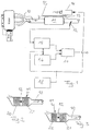
- the directional arrow 10 denotes the flowing exhaust gas from an internal combustion engine of a motor vehicle, which flows off through a catalytic converter designated overall by 11.
- Denoted by 12 is a pollutant sensor arranged downstream of the catalytic converter 11 in the flow direction 10 of the exhaust gas. responsive to hydrocarbons HC.
- a line 13 is provided upstream of the catalytic converter 11 and the pollutant sensor 12, via which air or pure oxygen is controlled to a defined extent, for example by means of a secondary air pump, from the device designated overall by 14.
- the output of the pollutant sensor 12 is electrically connected to an evaluation circuit 15. Its output and the output of a memory 16 are connected to the inputs of a circuit, denoted overall by 17, the output signal of which provides information about the functionality of the catalytic converter 11 or the lambda probes (not shown).
- a total of 18 designated Sequence control is connected both to the device 14 and to the evaluation circuit 15 and the memory 16.
- the sequence control causes a preferably rapid, defined change in the exhaust gas, namely a defined supply of secondary air, which corresponds to an emaciation of the fuel-air mixture.
- the evaluation circuit 15 for the pollutant sensor 12 and the memory 16 is activated in order to compare the prepared output signal of the pollutant sensor 12 at the output of the evaluation circuit 15 with a previously stored value profile in the comparison circuit 17 which corresponds to the defined change in the lambda value in the exhaust gas. If the values match, or if they lie within a specifiable tolerance range, the functionality of the catalytic converter and the lambda probes can be deduced. If they are outside, an error must be assumed.
- the arrangement referred to above with reference to FIG. 1 can have catalysts 11, as shown in FIGS. 2 or 3.
- two partial catalysts 20, 21 are provided in the form of monoliths in the exemplary embodiment shown.
- metalites can also be provided instead.
- the catalytic converter 11 can have a heatable partial catalytic converter 22 which is arranged in the flow direction 10 of the exhaust gas upstream of the pollutant sensor 12, behind which a further - unheated - catalytic converter 21 can then be arranged. Depending on the output signal of the pollutant sensor 12, the catalytic converter can be switched on via the evaluation circuit 15 as required.
Landscapes
- Engineering & Computer Science (AREA)
- Chemical & Material Sciences (AREA)
- Chemical Kinetics & Catalysis (AREA)
- Combustion & Propulsion (AREA)
- Mechanical Engineering (AREA)
- General Engineering & Computer Science (AREA)
- Health & Medical Sciences (AREA)
- Toxicology (AREA)
- Exhaust Gas After Treatment (AREA)
Abstract

Description
- Die Erfindung betrifft eine Anordnung gemäß dem Oberbegriff des Hauptanspruchs.
- Es sind Anordnungen zur Überprüfung der Funktionsfähigkeit von Katalysatoren mit zwei Lamdasonden für das Abgas von Verbrennungsmotoren in einer Vielzahl von Ausführungsformen bekannt (z.B. DE-23 04 464 C2). Diese bekannten Anordnungen bergen die Nachteile in sich, daß sie nicht hinreichend zuverlässig die Funktionsfähigkeit überwachen können, weil eine indirekte Messung entweder mit zwei Lambda-Sonden (DE 40 39 429) oder mittels Temperatursonden erfolgt.
- Es ist ferner eine gattungsgemäße Anordnung gemäß dem Oberbegriff des Hauptanspruchs bekannt (DE 43 23 243 A1), mit der von zwei Lambasonden das Konvertierungsvermögen des Katalysators bestimmt wird. Falls dieses ausreicht, wird nicht geheizt bzw. das Heizen eingestellt; ist es nicht ausreichend, so wird der Katalysator aufgeheizt, bis wieder ein ausreichendes Konvertierungsvermögen vorhanden ist. Führt das Heizen nicht zum Erfolg, so wird eine Diagnose zur Feststellung der Funktionsfähigkeit des Katalysators durchgeführt. Nachdem eine zuverlässige Feststellung der Funktionsfähigkeit bei gealterten Katalysatoren aufgrund der nicht mehr mit der Sauerstoffspeicherkapazität korrelierenden Umsatzrate an Kohlenwasserstoffen und anderen Schadstoffen nicht möglich ist, kann eine hireichend genaue Diagnose auch nicht erfolgen.
- Der Erfindung liegt deshalb die Aufgabe zugrunde, eine gattungsgemäße Anordnung gemäß dem Oberbegriff des Hauptanspruchs zuverlässiger sowie schnell reagierend auszubilden.
- Diese Aufgabe wird bei einer gattungsgemäßen Anordnung gemäß dem Oberbegriff des Hauptanspruchs erfindungsgemäß durch dessen kennzeichnende Merkmale gelöst.
- So werden also keine zwei Lambdasonden, sondern ein Schadstoffsensor in Strömungsrichtung des Abgas hinter oder in dem Katalysator angeordnet, wobei in Abhängigkeit von dem Ausgang der Auswerteschaltung (15) der beheizbare Katalysator aufgeheizt wird. Es ist mit Vorteil auch möglich, den Schadstoffsensor zwischen zwei oder mehreren einzelnen Katalysatoren anzuordnen, weil dann die definierte Änderung höhere Werte der Emissionsspitzen erreicht, diese vergleichsweise höheren Konzentrationen jedoch in dem nachfolgenden Katalysator abgebaut werden können, so daß die Feststellung der Funktionsfähigkeit zu keinem höheren Schadstoffausstoß führt.
- In vorteilhafter Ausgestaltung der Erfindung weist der Katalysator in Strömungsrichtung des Abgases einen beheizbaren Teilkatalysator auf, hinter dem der einzige Schadstoffsensor angeordnet ist, so daß in Abhängigkeit von dessen Ausgangssignal über die Auswerteschaltung der beheizbare Teilkatalysator betätigt werden kann. Dieser kann zweckmäßigerweise elektrisch beheizbar ausgebildet sein. In alternativer Ausführungsform ist es aber auch möglich, in Strömungsrichtung des Abgases nach dem Katalysator eine Umleiteinrichtung für das Abgas in eine Schadstoffalle vorzusehen, deren Ausgang mit dem Rohr mit dem Abgas verbunden ist, so daß während dieser Zeit, in welcher der Schadstoffsensor noch Schadstoffe nachweist, diese in der Schadstoffalle zurückgehalten werden. Erst wenn der Katalysator wieder unter seinen Betriebsbedingungen zufriedenstellend arbeitet, wird die Strömung mittels der Umschalteinrichtung durch die Schadstoffalle reversiert, so daß das zuvor abgefangene Abgas dann in Strömungsrichtung vor dem Katalysator wieder zugeführt wird.
- Wird also der beheizbare Teilkatalysator in Abhängigkeit von dem Ausgangssignal des Schadstoffsensors gesteuert, können Schadstoffemissionen in Kaltstartphasen minimiert werden. Außerdem kann eine Optimierung der Heizzeit erzielt werden, so daß bei Verwendung des Katalysators bei Kraftfahrzeugen deren Bordnetz nur soweit unbedingt notwendig, belastet wird. Mit dieser Vorrichtung ist ferner eine Kompensation von Alterungsphänomenen möglich, so daß hierdurch bedingt stets ein optimales Reinigungsverhalten des Katalysators erzielt werden kann. Nachdem die Schadstoffsensoren einerseits unmittelbar hinter dem beheizbaren Teilkatalysator angeordnet sind, andererseits schnell ansprechen, ist eine kurze Ansteuerzeit möglich. Sollte der elektrisch beheizbare Teilkatalysator während des Betriebs auskühlen und unter seine optimale Betriebstemperatur sinken, kann dies schnellstmöglich durch Nachheizen beseitigt werden. Hierzu ist es außerdem zweckmäßig, wenn ein weiterer Teilkatalysator in Strömungsrichtung des Abgases hinter dem Schadstoffsensor vorgesehen wird, der dann die von dem Schadstoffsensor gemessenen Schadstoffspitzen noch puffern bzw. egalisieren kann. Mit der Erfindung ist es also möglich, nicht nur den gegenwärtigen Betriebszustand des Katalysators nachzuregeln, sondern es werden auch künftige Alterungszustände des Katalysators durch die Erfindung berücksichtigt.
- Zweckmäßige Ausgestaltungen und Weiterbildungen der Erfindung sind in den Unteransprüchen gekennzeichnet.
- Ein bevorzugtes Ausführungsbeispiel wird nachfolgend unter Bezugnahme auf die Zeichnung näher erläutert. In dieser zeigt:
- Figur 1
- eine schematische Darstellung der erfindungsgemäßen Anordnung;
- Figur 2
- ein Ausführungsbeispiel für den Katalysator gemäß Figur 1 und
- Figur 3
- ein weiteres Ausführungsbeispiel für den Katalysator gemäß Figur 1
- Zunächst sei mit dem Richtungspfeil 10 das strömende Abgas aus einem Verbrennungsmotor eines Kraftfahrzeuges bezeichnet, das durch einen insgesamt mit 11 bezeichneten Katalysator abfließt. Mit 12 ist ein in Strömungsrichtung 10 des Abgases hinter dem Katalysator 11 angeordneter Schadstoffsensor bezeichnet, der z.B. auf Kohlenwasserstoffe HC anspricht. Vor dem Katalysator 11 und dem Schadstoffsensor 12 ist eine Leitung 13 vorgesehen, über die Luft oder reiner Sauerstoff in definiertem Maße gesteuert, beispielsweise über eine Sekundärluftpumpe von der insgesamt mit 14 bezeichneten Vorrichtung zuführbar ist.
- Der Ausgang des Schadstoffsensor 12 ist elektrisch mit einer Auswerteschaltung 15 verbunden. Dessen Ausgang sowie der Ausgang eines Speichers 16 sind mit den Eingängen einer insgesamt mit 17 bezeichneten Schaltung verbunden, deren Ausgangssignal Auskunft über die Funktionsfähigkeit des Katalysators 11 oder der (nicht gezeigten) Lambda-Sonden Auskunft gibt. Eine insgesamt mit 18 bezeichnete Ablaufsteuerung ist sowohl mit der Vorrichtung 14, als auch mit der Auswerteschaltung 15 sowie dem Speicher 16 verbunden.
- Durch die Ablaufsteuerung wird zum einen bewirkt, daß eine vorzugsweise schnelle definierte Änderung im Abgas, nämlich eine definierte Zuführung von Sekundärluft bewirkt wird, was einer Abmagerung des Kraftstoff-Luftgemisches entspricht. Zugleich wird die Auswerteschaltung 15 für den Schadstoffsensor 12 sowie der Speicher 16 aktiviert, um das aufbereitete Ausgangssignal des Schadstoffsensors 12 am Ausgang der Auswerteschaltung 15 mit einem zuvor gespeicherten, der definierten Änderung des Lambda-Wertes im Abgas entsprechenden Werteprofil in der Vergleichsschaltung 17 zu vergleichen. Stimmen die Werte überein, oder liegen sie innerhalb eines vorgebbaren Toleranzbereiches, so kann auf die Funktionsfähigkeit des Katalysators sowie der Lambda-Sonden geschlossen werden. Liegen sie außerhalb, muß von einem Fehler ausgegangen werden.
- Die vorstehend unter Bezugnahme auf Figur 1 bezeichnete Anordnung kann Katalysatoren 11, wie sie in den Figuren 2 oder 3 dargestellt sind, aufweisen. Bei der einen Ausführungsform gemäß Figur 2 des Katalysators 11 sind zwei Teilkatalysatoren 20, 21 beim wiedergegebenen Ausführungsbeispiel in Form von Monolithen vorgesehen. Selbstverständlich können statt dessen auch Metalite vorgesehen sein.
- In alternativer Ausführungsform kann der Katalysator 11 einen beheizbaren Teilkatalysator 22 aufweisen, der in Strömungsrichtung 10 des Abgases vor dem Schadstoffsensor 12 angeordnet ist, hinter dem dann noch ein weiterer - unbeheizter - Katalysator 21 nachgeordnet sein kann. In Abhängigkeit von dem Ausgangssignal des Schadstoffsensors 12 kann über die Auswerteschaltung 15 je nach Bedarf der Katalysator eingeschaltet werden.
Claims (7)
- Anordnung zur Steuerung der Heizung eines beheizbaren Katalysators (11) in Entgiftungsanlagen für Abgas, insbesondere beim Abgas von Verbrennungsmotoren von Kraftfahrzeugen , wobei in Strömungsrichtung (10) des Abgases hinter oder in dem Katalysator (11) ein Sensor (12) angeordnet ist und das elektrische Ausgangssignal des Sensors (12) über eine Auswerteschaltung (15) ausgewertet wird,
dadurch gekennzeichnet,
daß der einzige Sensor in Strömungsrichtung (10) des Abgases hinter oder in dem Katalysator (11) als Schadstoffsensor (12) ausbebildet ist, daß über den Ausgangs der Auswerteschaltung (15) der beheizbare Katalysator aufgeheizt wird. - Anordnung nach Anspruch 1, dadurch gekennzeichnet, daß als Schadstoffsensor (12) ein NO-, CO- oder HC-Sensor verwendet wird.
- Anordnung nach Anspruch 1, dadurch gekennzeichnet, daß der Katalysator (11) zwei Monolithe (20, 21) als Teilkatalysatoren aufweist, zwischen denen der Schadstoffsensor (12) angeordnet ist.
- Anordnung nach einem der Ansprüche 1 bis 3, dadurch gekennzeichnet, daß der Katalysator (11) in Strömungsrichtung (10) des Abgases einen beheizbaren Teilkatalysator (22) aufweist und daß hinter diesem der Schadstoffsensor (11) angeordnet ist.
- Anordnung nach Anspruch 4, dadurch gekennzeichnet, daß der beheizbare Teilkatalysator (22) als elektrisch und/oder mit einer Flamme beheizbar ausgebildet ist.
- Anordnung nach Anspruch 4, dadurch gekennzeichnet, daß in Strömungsrichtung (10) des Abgases nach dem Katalysator (11) eine Umleitvorrichtung für das Abgas in eine Schadstoffalle vorgesehen ist, deren Ausgang mit dem Rohr mit dem Abgas verbunden ist.
- Anordnung nach einem der Ansprüche 1 bis 6, dadurch gekennzeichnet, daß in Abhängigkeit von dem elektrischen Ausgangssignal des Schadgassensors (12) der beheizbare Teilkatalysator (22) oder die Umschalteinrichtung betätigbar ist.
Applications Claiming Priority (2)
| Application Number | Priority Date | Filing Date | Title |
|---|---|---|---|
| DE19512298 | 1995-04-05 | ||
| DE19512298A DE19512298A1 (de) | 1995-04-05 | 1995-04-05 | Emissionsgeregelte Anordnung zur Katalytischenschadstoffreduzierung von Katalysatoren |
Publications (3)
| Publication Number | Publication Date |
|---|---|
| EP0736675A2 true EP0736675A2 (de) | 1996-10-09 |
| EP0736675A3 EP0736675A3 (de) | 1997-08-27 |
| EP0736675B1 EP0736675B1 (de) | 2000-06-14 |
Family
ID=7758563
Family Applications (1)
| Application Number | Title | Priority Date | Filing Date |
|---|---|---|---|
| EP96105472A Expired - Lifetime EP0736675B1 (de) | 1995-04-05 | 1996-04-04 | Anordnung zur Steuerung der Heizung von beheizbaren Katalysatoren |
Country Status (2)
| Country | Link |
|---|---|
| EP (1) | EP0736675B1 (de) |
| DE (2) | DE19512298A1 (de) |
Family Cites Families (9)
| Publication number | Priority date | Publication date | Assignee | Title |
|---|---|---|---|---|
| DE4022546A1 (de) * | 1990-07-16 | 1992-01-23 | Emitec Emissionstechnologie | Messfuehler fuer ein abgassystem und verfahren zu seinem betrieb |
| JP2666532B2 (ja) * | 1990-07-30 | 1997-10-22 | トヨタ自動車株式会社 | 内燃機関の空燃比制御装置 |
| DE4035971A1 (de) * | 1990-11-12 | 1992-05-14 | Emitec Emissionstechnologie | Beheizbare katalysatoranordnung fuer die abgasreinigung von verbrennungsmotoren |
| JP2663720B2 (ja) * | 1990-12-26 | 1997-10-15 | トヨタ自動車株式会社 | ディーゼルエンジンの排気浄化装置 |
| US5201802A (en) * | 1991-02-04 | 1993-04-13 | Toyota Jidosha Kabushiki Kaisha | Exhaust gas purification system for an internal combustion engine |
| JP2504265Y2 (ja) * | 1991-06-24 | 1996-07-10 | 本田技研工業株式会社 | 排気浄化触媒装置 |
| JPH05231135A (ja) * | 1992-02-18 | 1993-09-07 | Toyota Motor Corp | 内燃機関の排気浄化装置 |
| DE4323243A1 (de) * | 1993-07-12 | 1995-01-26 | Bosch Gmbh Robert | Bedarfsorientiertes Heizverfahren für einen Katalysator im Abgassystem einer Brennkraftmaschine |
| DE4338547A1 (de) * | 1993-11-11 | 1995-05-18 | Bosch Gmbh Robert | Vorrichtung und Verfahren zur Überwachung eines Katalysators in einem Kraftfahrzeug |
-
1995
- 1995-04-05 DE DE19512298A patent/DE19512298A1/de not_active Withdrawn
-
1996
- 1996-04-04 EP EP96105472A patent/EP0736675B1/de not_active Expired - Lifetime
- 1996-04-04 DE DE59605426T patent/DE59605426D1/de not_active Expired - Fee Related
Also Published As
| Publication number | Publication date |
|---|---|
| DE59605426D1 (de) | 2000-07-20 |
| EP0736675A3 (de) | 1997-08-27 |
| DE19512298A1 (de) | 1996-10-24 |
| EP0736675B1 (de) | 2000-06-14 |
Similar Documents
| Publication | Publication Date | Title |
|---|---|---|
| DE102008038677B4 (de) | Verfahren und Vorrichtung zum Diagnostizieren eines Abgaskatalysators | |
| EP1084331B1 (de) | Verfahren und vorrichtung zum überwachen der funktionsfähigkeit eines katalysators einer brennkraftmaschine | |
| WO2018029230A1 (de) | Diagnoseverfahren und vorrichtung zur überprüfung der funktionsfähigkeit einer komponente zur abgasnachbehandlung | |
| EP1117917B1 (de) | VERFAHREN ZUM REGENERIEREN EINES NOx-SPEICHERKATALYSATORS | |
| DE19620417C2 (de) | Diagnoseverfahren und Diagnosesystem einer Katalysatoranlage zum Steuern des Abgases bei einem Verbrennungsmotor | |
| WO2018104425A1 (de) | Verfahren und steuergerät zur durchführung von diagnosen eines abgassystems eines verbrennungsmotors | |
| DE19913949C2 (de) | Steuervorrichtung zur Abgasreinigung für Brennkraftmaschinen | |
| DE10012839B4 (de) | Regenerationskraftstoffsteuerung eines NOx-Adsorbersystems | |
| EP0530655B1 (de) | Verfahren und Vorrichtung zur Regelung eines Otto-Motors und Prüfung eines ihm nachgeschalteten Katalysators | |
| DE10309422B4 (de) | Verfahren und Vorrichtung zur Kalibrierung eines NOx-Sensors | |
| EP1205648B1 (de) | Verfahren und Vorrichtung zur Katalysatorbeheizung | |
| DE102015200762A1 (de) | Verfahren zur Überwachung einer Abgasnachbehandlungsanlage eines Verbrennungsmotors sowie Steuerungseinrichtung für eine Abgasnachbehandlungsanlage | |
| DE102015200751B4 (de) | Verfahren zur Überwachung einer Abgasnachbehandlungsanlage eines Verbrennungsmotors sowie Steuerungseinrichtung für eine Abgasnachbehandlungsanlage | |
| DE4310961C1 (de) | Verfahren zum selektiven katalytischen Reduzieren der Stickoxide im Abgas einer Brennkraftmaschine | |
| DE69407557T2 (de) | Katalysatorüberwachung für Y-Abgasrohranordnung | |
| EP1365234A2 (de) | Verfahren zur Korrektur des NOx-Signals eines NOx-Sensors | |
| WO2001019499A1 (de) | Verfahren zum betrieb eines scr-katalysators | |
| EP0793770B1 (de) | Anordnung zur überwachung der funktionsfähigkeit von katalysatoren | |
| EP1138898B1 (de) | Verfahren und Vorrichtung zur Abgasreinigung | |
| DE10257059B4 (de) | Verfahren und Vorrichtung zur Diagnose von Katalysatoreinheiten | |
| DE102004015131B4 (de) | Verfahren zum Betreiben einer Brennkraftmaschine und Vorrichtung zur Durchführung des Verfahrens | |
| DE19909796A1 (de) | Verfahren und Vorrichtung zur Abgastemperaturerhöhung | |
| EP0736675B1 (de) | Anordnung zur Steuerung der Heizung von beheizbaren Katalysatoren | |
| DE602004001282T2 (de) | Unterstützungssystem zum regenerieren einer NOx Falle | |
| EP0881367B1 (de) | Katalysatorsystem zur Entstickung von Abgasen bei Dieselbrennkraftmaschinen |
Legal Events
| Date | Code | Title | Description |
|---|---|---|---|
| PUAI | Public reference made under article 153(3) epc to a published international application that has entered the european phase |
Free format text: ORIGINAL CODE: 0009012 |
|
| AK | Designated contracting states |
Kind code of ref document: A2 Designated state(s): DE FR GB IT |
|
| RAP1 | Party data changed (applicant data changed or rights of an application transferred) |
Owner name: HERAEUS ELECTRO-NITE INTERNATIONAL N.V. |
|
| PUAL | Search report despatched |
Free format text: ORIGINAL CODE: 0009013 |
|
| RAP1 | Party data changed (applicant data changed or rights of an application transferred) |
Owner name: HAEFELE, CORNELIA |
|
| AK | Designated contracting states |
Kind code of ref document: A3 Designated state(s): DE FR GB IT |
|
| RAP1 | Party data changed (applicant data changed or rights of an application transferred) |
Owner name: HERAEUS ELECTRO-NITE INTERNATIONAL N.V. |
|
| 17P | Request for examination filed |
Effective date: 19971007 |
|
| 17Q | First examination report despatched |
Effective date: 19980929 |
|
| GRAG | Despatch of communication of intention to grant |
Free format text: ORIGINAL CODE: EPIDOS AGRA |
|
| GRAG | Despatch of communication of intention to grant |
Free format text: ORIGINAL CODE: EPIDOS AGRA |
|
| GRAH | Despatch of communication of intention to grant a patent |
Free format text: ORIGINAL CODE: EPIDOS IGRA |
|
| GRAH | Despatch of communication of intention to grant a patent |
Free format text: ORIGINAL CODE: EPIDOS IGRA |
|
| GRAA | (expected) grant |
Free format text: ORIGINAL CODE: 0009210 |
|
| AK | Designated contracting states |
Kind code of ref document: B1 Designated state(s): DE FR GB IT |
|
| GBT | Gb: translation of ep patent filed (gb section 77(6)(a)/1977) |
Effective date: 20000615 |
|
| REF | Corresponds to: |
Ref document number: 59605426 Country of ref document: DE Date of ref document: 20000720 |
|
| ITF | It: translation for a ep patent filed | ||
| ET | Fr: translation filed | ||
| PGFP | Annual fee paid to national office [announced via postgrant information from national office to epo] |
Ref country code: GB Payment date: 20010316 Year of fee payment: 6 |
|
| PLBE | No opposition filed within time limit |
Free format text: ORIGINAL CODE: 0009261 |
|
| STAA | Information on the status of an ep patent application or granted ep patent |
Free format text: STATUS: NO OPPOSITION FILED WITHIN TIME LIMIT |
|
| 26N | No opposition filed | ||
| REG | Reference to a national code |
Ref country code: GB Ref legal event code: IF02 |
|
| PG25 | Lapsed in a contracting state [announced via postgrant information from national office to epo] |
Ref country code: GB Free format text: LAPSE BECAUSE OF NON-PAYMENT OF DUE FEES Effective date: 20020404 |
|
| PGFP | Annual fee paid to national office [announced via postgrant information from national office to epo] |
Ref country code: FR Payment date: 20020430 Year of fee payment: 7 |
|
| PGFP | Annual fee paid to national office [announced via postgrant information from national office to epo] |
Ref country code: DE Payment date: 20020510 Year of fee payment: 7 |
|
| GBPC | Gb: european patent ceased through non-payment of renewal fee |
Effective date: 20020404 |
|
| PG25 | Lapsed in a contracting state [announced via postgrant information from national office to epo] |
Ref country code: DE Free format text: LAPSE BECAUSE OF NON-PAYMENT OF DUE FEES Effective date: 20031101 |
|
| PG25 | Lapsed in a contracting state [announced via postgrant information from national office to epo] |
Ref country code: FR Free format text: LAPSE BECAUSE OF NON-PAYMENT OF DUE FEES Effective date: 20031231 |
|
| REG | Reference to a national code |
Ref country code: FR Ref legal event code: ST |
|
| PG25 | Lapsed in a contracting state [announced via postgrant information from national office to epo] |
Ref country code: IT Free format text: LAPSE BECAUSE OF NON-PAYMENT OF DUE FEES Effective date: 20050404 |