EP0735350A2 - Spectroscope avec un branchement à fibre optique - Google Patents
Spectroscope avec un branchement à fibre optique Download PDFInfo
- Publication number
- EP0735350A2 EP0735350A2 EP96104986A EP96104986A EP0735350A2 EP 0735350 A2 EP0735350 A2 EP 0735350A2 EP 96104986 A EP96104986 A EP 96104986A EP 96104986 A EP96104986 A EP 96104986A EP 0735350 A2 EP0735350 A2 EP 0735350A2
- Authority
- EP
- European Patent Office
- Prior art keywords
- light
- optical
- measurement
- spectroscope
- incident
- Prior art date
- Legal status (The legal status is an assumption and is not a legal conclusion. Google has not performed a legal analysis and makes no representation as to the accuracy of the status listed.)
- Granted
Links
- 239000013307 optical fiber Substances 0.000 title claims abstract description 92
- 230000003287 optical effect Effects 0.000 claims abstract description 39
- 238000005259 measurement Methods 0.000 claims abstract description 37
- 230000010354 integration Effects 0.000 claims description 5
- 230000003595 spectral effect Effects 0.000 abstract description 8
- 230000007613 environmental effect Effects 0.000 abstract description 7
- 238000001228 spectrum Methods 0.000 description 6
- 238000010586 diagram Methods 0.000 description 4
- 230000006866 deterioration Effects 0.000 description 2
- 239000011521 glass Substances 0.000 description 2
- 230000009466 transformation Effects 0.000 description 2
- 230000002238 attenuated effect Effects 0.000 description 1
- WUKWITHWXAAZEY-UHFFFAOYSA-L calcium difluoride Chemical compound [F-].[F-].[Ca+2] WUKWITHWXAAZEY-UHFFFAOYSA-L 0.000 description 1
- 229910001634 calcium fluoride Inorganic materials 0.000 description 1
- 230000015556 catabolic process Effects 0.000 description 1
- 239000013078 crystal Substances 0.000 description 1
- 238000006731 degradation reaction Methods 0.000 description 1
- 230000008021 deposition Effects 0.000 description 1
- 238000001514 detection method Methods 0.000 description 1
- 230000000694 effects Effects 0.000 description 1
- 239000000835 fiber Substances 0.000 description 1
- 239000010408 film Substances 0.000 description 1
- 230000004927 fusion Effects 0.000 description 1
- 230000001678 irradiating effect Effects 0.000 description 1
- 239000010453 quartz Substances 0.000 description 1
- VYPSYNLAJGMNEJ-UHFFFAOYSA-N silicon dioxide Inorganic materials O=[Si]=O VYPSYNLAJGMNEJ-UHFFFAOYSA-N 0.000 description 1
- 239000010409 thin film Substances 0.000 description 1
- 238000007738 vacuum evaporation Methods 0.000 description 1
Images

Classifications
-
- G—PHYSICS
- G01—MEASURING; TESTING
- G01J—MEASUREMENT OF INTENSITY, VELOCITY, SPECTRAL CONTENT, POLARISATION, PHASE OR PULSE CHARACTERISTICS OF INFRARED, VISIBLE OR ULTRAVIOLET LIGHT; COLORIMETRY; RADIATION PYROMETRY
- G01J3/00—Spectrometry; Spectrophotometry; Monochromators; Measuring colours
- G01J3/28—Investigating the spectrum
- G01J3/45—Interferometric spectrometry
- G01J3/453—Interferometric spectrometry by correlation of the amplitudes
- G01J3/4535—Devices with moving mirror
Definitions
- the present invention relates to a spectroscope, such as Fourier-transform spectroscopes or dispersive spectroscopes, especially to an improvement in the accuracy of measured data by these spectroscopes.
- a spectroscope such as Fourier-transform spectroscopes or dispersive spectroscopes
- Conventional Fourier-transform spectroscopes were configured to obtain the spectral characteristics of samples by irradiating the above samples through an optical fiber with an outgoing light from a Michelson interferometer on which white light was incident from a white-light source (hereafter abbreviated as light source), and by converting the transmitted light from the samples to electrical signals using a photo-detector (hereafter abbreviated as detector) and further implementing a Fourier transformation.
- a Michelson interferometer on which white light was incident from a white-light source
- detector photo-detector
- Figure 1 shows a configuration block diagram for an example of such a conventional Fourier-transform spectroscope.
- White light emitted from light source 1 is changed to parallel light first by optical means 2, which normally uses a lens, and is incident on Michelson interferometer 50.
- the interference light obtained at Michelson interferometer 50 is focused by second optical means (which normally uses a lens) 6 and is incident on optical fiber 7.
- This interference light after transmitting sample 8, is incident on detector 10 through optical fiber 9.
- optical fiber 11 and detector 12 are added. More closely, in a position where the image of light source 1 forms, optical fiber 11 is located close to and along optical fiber 7. Optical fiber 11 is arranged so that it takes the same path of the optical fibers 7 and 9 except that there is no sample on its way and its optical characteristic is also the same as optical fibers 7 and 9.
- Outgoing light from optical fiber 11 is detected by detector 12 and processed in an identical manner to the interference signal detected by detector 10.
- the changes in optical fiber 11 are considered identical to those in optical fibers 7 and 9 because optical fiber 11 takes the same path as optical fibers 7 and 9, the environmental changes in the optical fiber can be compensated by taking the ratio of both interference signal spectra.
- Michelson interferometer 50 is also subjected to effects, such as temperature changes, and if the internal mirrors become tilted due to such temperature change, the interference light in the position of "d" in Figure 2 becomes non-uniform.
- the problem still remains that this results in different characteristics between the interference light incident on optical fiber 7 and that incident on optical fiber 11, and so this difference is not compensated but measured superimposed on the spectral characteristics of sample 8.
- AOTF 60 branches the incident light from light source 1 to two light beams because of the birefringence of its crystal. These beams are made parallel with lens 13 and each parallelized beam is focused with lenses 14 and 15 and is incident on each optical fiber. In this case, an arbitrary wavelength or continuous wavelength light can be taken out by changing the frequency of the ultrasonic wave generated with ultrasonic generator 16.
- the light from light source 1 is reflected with concave mirror 17a, applied to diffraction grating 18, and the refracted light is again reflected with concave mirror 17b and is incident on sample optical fiber 7 and reference optical fiber 11.
- the wavelength of the light incident on optical fibers 7 and 11 can be changed by rotating grating 18.
- the purpose of the present invention in view of the above problems, lies in implementing a spectroscope which can accurately measure the spectral characteristics of samples even if the outgoing light from the spectroscope light source (including an original light source and an interferometer or the like) becomes non-uniform due to environmental changes on the spectroscope side by providing a configuration in which, after receiving the light from the spectroscope light source side with a single optical fiber, the light branches off to two optical fibers.
- the present invention comprises, in a spectroscope using at least two optical fibers for measurement and reference purposes in the light path to the sample chamber, a first optical fiber arranged so that its input end is located in the outgoing light path to the above sample chamber; an optical coupler which divides the output light of the first optical fiber into two and makes these two branched light beams be incident to the measurement and reference optical fibers respectively; and first and second detectors to detect the output light from each measurement and reference optical fiber respectively.
- the spectral characteristics can be accurately measured since the outgoing light beam from the spectroscope light source side is incident on both the measurement and the reference optical fibers in common even if the outgoing light beam becomes non-uniform due to environmental changes on the spectroscope light source side.
- Figure 1 is an example of the configuration of conventional Fourier-transform spectroscopes.
- Figure 2 is an example of the configuration of another conventional Fourier-transform spectroscopes.
- Figure 3 is an example of the configuration of conventional spectroscopes using an acousto-optical device.
- Figure 4 is an example of the configuration of conventional spectroscopes using a diffraction grating.
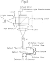
- Figure 5 is a diagram showing an embodiment related to the present invention.
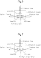
- Figure 6 shows an embodiment to illustrate the details of an optical coupler.
- Figure 7 shows another embodiment to illustrate an optical coupler.
- Figure 8 shows yet another embodiment of the optical coupler.
- Figure 9 shows a fourth embodiment of the optical coupler.
- Figure 5 is a diagram showing an example of an embodiment of the spectroscope related to the present invention.
- Figure 5 the same symbols as in Figure 2 are given to the equivalent parts in the figure and the description of those parts is omitted.
- Figure 6 shows an embodiment of the present invention to illustrate the details of optical coupler 20.
- the optical coupler uses a half mirror. Outgoing light from optical fiber 19 is parallelized with lens 201 and is incident on half mirror 204. Half mirror 204 transmits a part of the incident light and the transmitted light is focused with lens 202 and incident on the end face of optical fiber 7. Also, the light reflected from half mirror 204 is focused with lens 203 and incident on the end face of optical fiber 11.
- Figure 7 shows a light coupler using a right angle mirror.
- Outgoing light from optical fiber 19 is parallelized with lens 205 and is incident on right angle mirror 208.
- Right angle mirror 208 reflects the left half of the incident light beam towards lens 206 and this beam is focused with lens 206 and is incident on the end face of optical fiber 11.
- Right angle mirror 208 reflects similarly the right half the incident light beam towards lens 207 and this beam is focused with lens 207 and is incident on the end face of optical fiber 7.
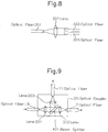
- Figure 8 shows another embodiment of this invention to illustrate the optical coupler using a lens. Outgoing light from first optical fiber 301 is parallelized with lens 302 and then is incident on second and third optical fibers 303 and 304.
- the characteristics of light source 1 and optical fibers 19, 7, and 9 are included in addition to those of sample 8 in the spectrum of the measurement signal, while the characteristics of light source 1 and optical fibers 19 and 11 are included in the spectrum of the reference signal.
- optical fiber 11 As optical fiber 11 is located in the same path of optical fibers 7 and 9, optical fiber 11 and optical fibers 7 and 9 show identical characteristics. Therefore, by dividing the spectrum characteristics of the measurement signal by those of the reference signal, the environmental changes in optical fibers 19, 7, and 9 can be compensated.
- the non-uniformity of interference light in position "d,” which is generated by the tilting of the mirrors due to temperature changes and influences by signals in the configuration in Figure 5, can also be compensated because the light is received with a single optical fiber in the position of "d" and then divided into the lights for the measurement and reference signals.
- This configuration is also similarly effective for the deterioration of the light source.
- the present invention is not limited to the above examples of embodiment.
- those using general, commercially available optical wave-guides and fusion splice optical fibers can also be used.
- the present invention can also be configured so that the measurement and reference signals can be taken out by arranging optical fibers close to each other in the position of "d" shown in Figure 5 as indicated in the examples of a conventional configuration in Figure 2, and by attaching optical couplers to each optical fiber.
- multi-channel measurement will be available using an interferometer as a light source.
- light quantities for measurement and reference signals are not necessarily 1 : 1.
- the light quantity on the measurement signal side is attenuated by the sample and sample chamber. Accordingly, if the light quantity on the measurement signal side is correspondingly increased, for example, by setting the light quantity ratio on the measurement and reference sides to 2 : 1, the loss due to samples and others can be compensated, and a collectively higher S/N ratio than the case of a ratio of 1 : 1 can be obtained.
- Figure 9 is a diagram of an optical coupler that realizes this concept.
- Light from optical fiber 19 is separated by beam splitter 401 before being incident on optical fiber 7 on the sample side and the divided light is incident on optical fiber 11 on the reference side.
- beam splitter 401 For a near-infrared ray, a glass plate itself without metal-film deposition by vacuum evaporation can be used because the surface reflection from the glass surface is about 4%.
- the integration time on the reference side which can follow temperature changes in the light source and optical fibers itself is sufficient, while that time on the measurement side must be determined following the sample changes.
- the integration response time 1 to 10 seconds, while the time constant of a few to tens of minutes is enough for temperature changes in the light source and optical fibers on the reference side. That is, the integration time on the reference side can be several to tens of times that on the measurement side.
- the above beam splitter may be made of quartz or calcium fluoride.
- a splitter not utilizing surface reflection but utilizing a thin film applied to its surface may be used, although durability becomes slightly lower.
- the ratio of the reference light to the measurement light is not limited to the above value but it is sufficient that the light quantity on the reference side is smaller than that on the measurement side.
- the spectroscope by the present invention can provide accurate measurement without being affected by temperature and other changes in the interferometer part because its configuration is taken to receive the outgoing interference light from a Michelson interferometer with a single optical fiber and then branch the light into two optical fibers using an optical coupler to make the measurement and reference signals.
Landscapes
- Physics & Mathematics (AREA)
- Spectroscopy & Molecular Physics (AREA)
- General Physics & Mathematics (AREA)
- Spectrometry And Color Measurement (AREA)
- Investigating Or Analysing Materials By Optical Means (AREA)
Applications Claiming Priority (3)
| Application Number | Priority Date | Filing Date | Title |
|---|---|---|---|
| JP74952/95 | 1995-03-31 | ||
| JP7495295 | 1995-03-31 | ||
| JP7074952A JPH08271337A (ja) | 1995-03-31 | 1995-03-31 | 分光器 |
Publications (3)
| Publication Number | Publication Date |
|---|---|
| EP0735350A2 true EP0735350A2 (fr) | 1996-10-02 |
| EP0735350A3 EP0735350A3 (fr) | 1997-04-09 |
| EP0735350B1 EP0735350B1 (fr) | 2002-02-06 |
Family
ID=13562180
Family Applications (1)
| Application Number | Title | Priority Date | Filing Date |
|---|---|---|---|
| EP96104986A Expired - Lifetime EP0735350B1 (fr) | 1995-03-31 | 1996-03-28 | Spectroscope avec un branchement à fibre optique |
Country Status (4)
| Country | Link |
|---|---|
| US (1) | US5715055A (fr) |
| EP (1) | EP0735350B1 (fr) |
| JP (1) | JPH08271337A (fr) |
| DE (2) | DE69619010T2 (fr) |
Cited By (1)
| Publication number | Priority date | Publication date | Assignee | Title |
|---|---|---|---|---|
| EP1058110A1 (fr) * | 1998-03-18 | 2000-12-06 | Datex-Ohmeda, Inc. | Moniteur de gaz respiratoire dans le courant principal, utilisant des signaux infrarouges transformés |
Families Citing this family (7)
| Publication number | Priority date | Publication date | Assignee | Title |
|---|---|---|---|---|
| WO2000025086A1 (fr) | 1998-10-23 | 2000-05-04 | Mission Research Corporation | Appareil et procede de production d'une source de rayonnement spectralement variable et systemes la comprenant |
| US6480330B1 (en) * | 2000-02-24 | 2002-11-12 | Silicon Valley Group, Inc. | Ultraviolet polarization beam splitter for microlithography |
| US7414785B2 (en) * | 2000-02-24 | 2008-08-19 | Asml Holding N.V. | Ultraviolet polarization beam splitter with minimum apodization |
| US7079252B1 (en) * | 2000-06-01 | 2006-07-18 | Lifescan, Inc. | Dual beam FTIR methods and devices for use in analyte detection in samples of low transmissivity |
| RU167678U1 (ru) * | 2016-07-27 | 2017-01-10 | Российская Федерация, от имени которой выступает Государственная корпорация по космической деятельности "РОСКОСМОС" (Госкорпорация "РОСКОСМОС") | Фурье-спектрометр |
| JP6939360B2 (ja) * | 2017-10-02 | 2021-09-22 | オムロン株式会社 | 共焦点計測装置 |
| JP7226243B2 (ja) * | 2019-10-29 | 2023-02-21 | 横河電機株式会社 | フーリエ分光分析装置 |
Citations (9)
| Publication number | Priority date | Publication date | Assignee | Title |
|---|---|---|---|---|
| DE2929186A1 (de) * | 1979-07-19 | 1981-02-05 | Licentia Gmbh | Einrichtung zur auskopplung eines definierten anteils eines lichtbuendels einer lichtleitfaser |
| US4538910A (en) * | 1982-09-30 | 1985-09-03 | Laser Precision Corporation | Dual beam fourier spectrometer |
| US4696570A (en) * | 1985-04-23 | 1987-09-29 | Centre National De La Recherche Scientifique (C.N.R.S.) | Spectrophotometer with statistically balanced light for very high resolution |
| EP0262878A2 (fr) * | 1986-10-03 | 1988-04-06 | AT&T Corp. | Connecteur pour des fibres optiques |
| WO1990007697A1 (fr) * | 1989-01-04 | 1990-07-12 | Guided Wave, Inc. | Spectrophotometre a double fibre optique |
| EP0431805A2 (fr) * | 1989-12-05 | 1991-06-12 | The Whitaker Corporation | Couplage par réflexion des fibres optiques |
| WO1991014157A2 (fr) * | 1990-03-05 | 1991-09-19 | Bran + Luebbe Gmbh | Spectrometre acousto-optique a double faisceau accordable |
| US5212748A (en) * | 1990-07-11 | 1993-05-18 | Curtiss Lawrence E | Fiber optic mixer and spectrometer |
| EP0634677A1 (fr) * | 1993-07-16 | 1995-01-18 | Sumitomo Electric Industries, Limited | Dispositif de guide d'ondes optiques |
Family Cites Families (1)
| Publication number | Priority date | Publication date | Assignee | Title |
|---|---|---|---|---|
| DE3044183A1 (de) * | 1980-11-24 | 1982-06-24 | Reinhard Dipl.-Phys. Dr. 7250 Leonberg Ulrich | Verfahren zur optischen messung von laengen und laengenaenderungen und anordnung zur durchfuehrung des verfahrens |
-
1995
- 1995-03-31 JP JP7074952A patent/JPH08271337A/ja active Pending
-
1996
- 1996-03-18 US US08/619,951 patent/US5715055A/en not_active Expired - Lifetime
- 1996-03-28 DE DE69619010T patent/DE69619010T2/de not_active Expired - Lifetime
- 1996-03-28 EP EP96104986A patent/EP0735350B1/fr not_active Expired - Lifetime
- 1996-03-28 DE DE0735350T patent/DE735350T1/de active Pending
Patent Citations (9)
| Publication number | Priority date | Publication date | Assignee | Title |
|---|---|---|---|---|
| DE2929186A1 (de) * | 1979-07-19 | 1981-02-05 | Licentia Gmbh | Einrichtung zur auskopplung eines definierten anteils eines lichtbuendels einer lichtleitfaser |
| US4538910A (en) * | 1982-09-30 | 1985-09-03 | Laser Precision Corporation | Dual beam fourier spectrometer |
| US4696570A (en) * | 1985-04-23 | 1987-09-29 | Centre National De La Recherche Scientifique (C.N.R.S.) | Spectrophotometer with statistically balanced light for very high resolution |
| EP0262878A2 (fr) * | 1986-10-03 | 1988-04-06 | AT&T Corp. | Connecteur pour des fibres optiques |
| WO1990007697A1 (fr) * | 1989-01-04 | 1990-07-12 | Guided Wave, Inc. | Spectrophotometre a double fibre optique |
| EP0431805A2 (fr) * | 1989-12-05 | 1991-06-12 | The Whitaker Corporation | Couplage par réflexion des fibres optiques |
| WO1991014157A2 (fr) * | 1990-03-05 | 1991-09-19 | Bran + Luebbe Gmbh | Spectrometre acousto-optique a double faisceau accordable |
| US5212748A (en) * | 1990-07-11 | 1993-05-18 | Curtiss Lawrence E | Fiber optic mixer and spectrometer |
| EP0634677A1 (fr) * | 1993-07-16 | 1995-01-18 | Sumitomo Electric Industries, Limited | Dispositif de guide d'ondes optiques |
Cited By (1)
| Publication number | Priority date | Publication date | Assignee | Title |
|---|---|---|---|---|
| EP1058110A1 (fr) * | 1998-03-18 | 2000-12-06 | Datex-Ohmeda, Inc. | Moniteur de gaz respiratoire dans le courant principal, utilisant des signaux infrarouges transformés |
Also Published As
| Publication number | Publication date |
|---|---|
| EP0735350A3 (fr) | 1997-04-09 |
| DE735350T1 (de) | 1997-04-30 |
| JPH08271337A (ja) | 1996-10-18 |
| DE69619010T2 (de) | 2003-01-30 |
| US5715055A (en) | 1998-02-03 |
| EP0735350B1 (fr) | 2002-02-06 |
| DE69619010D1 (de) | 2002-03-21 |
Similar Documents
| Publication | Publication Date | Title |
|---|---|---|
| US4260883A (en) | Optical measurement system | |
| US6992779B2 (en) | Interferometer apparatus for both low and high coherence measurement and method thereof | |
| US6043883A (en) | Wavemeter and an arrangement for the adjustment of the wavelength of the signals of an optical source | |
| US5712705A (en) | Arrangement for analysis of substances at the surface of an optical sensor | |
| US5619326A (en) | Method of sample valuation based on the measurement of photothermal displacement | |
| JP4151159B2 (ja) | 媒質の測定装置 | |
| US20110032529A1 (en) | Universal wavelength calibration source using a stable monolithic interferometer | |
| JPH0231113A (ja) | 干渉計センサ及び干渉計装置における該センサの使用 | |
| US7692796B2 (en) | Optical characteristic measuring apparatus | |
| EP0735350B1 (fr) | Spectroscope avec un branchement à fibre optique | |
| US20140347659A1 (en) | Stationary Waveguide Spectrum Analyser | |
| US6714301B2 (en) | Spectral ellipsometer without chromatic aberrations | |
| JPH03504768A (ja) | 特に可動な構成要素の距離及至シフト運動を測定するための干渉計システム | |
| US6590666B2 (en) | Method and system for optical spectrum analysis with non-uniform sweep rate correction | |
| JP3528482B2 (ja) | フーリエ分光器 | |
| US20030202799A1 (en) | Optical channel monitor using an angle-tuned fabry-perot optical filter | |
| JP2001091357A (ja) | 多重光スペクトルの同時分析方法 | |
| US6298185B1 (en) | Distributed fiber grating sensing systems using birefringence fiber interferometers for detecting wavelength shifts | |
| JP3287441B2 (ja) | 光線路識別用光部品並びにその遠隔測定方法及び装置 | |
| JPS599526A (ja) | 温度測定装置 | |
| JPS633236A (ja) | 光フアイバの波長分散測定器 | |
| EP0499545B1 (fr) | Récepteur de démultiplexage parallèle pour un réseau de capteurs optiques à codage de modulation spectrale | |
| JPH10232109A (ja) | 光変位センサー | |
| JPH0658293B2 (ja) | 光フアイバの波長分散測定方法および装置 | |
| JPH11274643A (ja) | 可変波長半導体レーザ光源 |
Legal Events
| Date | Code | Title | Description |
|---|---|---|---|
| PUAI | Public reference made under article 153(3) epc to a published international application that has entered the european phase |
Free format text: ORIGINAL CODE: 0009012 |
|
| 17P | Request for examination filed |
Effective date: 19960424 |
|
| AK | Designated contracting states |
Kind code of ref document: A2 Designated state(s): DE NL |
|
| TCNL | Nl: translation of patent claims filed | ||
| PUAL | Search report despatched |
Free format text: ORIGINAL CODE: 0009013 |
|
| AK | Designated contracting states |
Kind code of ref document: A3 Designated state(s): DE GB NL |
|
| DET | De: translation of patent claims | ||
| 17Q | First examination report despatched |
Effective date: 19991227 |
|
| GRAG | Despatch of communication of intention to grant |
Free format text: ORIGINAL CODE: EPIDOS AGRA |
|
| GRAG | Despatch of communication of intention to grant |
Free format text: ORIGINAL CODE: EPIDOS AGRA |
|
| GRAH | Despatch of communication of intention to grant a patent |
Free format text: ORIGINAL CODE: EPIDOS IGRA |
|
| GRAH | Despatch of communication of intention to grant a patent |
Free format text: ORIGINAL CODE: EPIDOS IGRA |
|
| GRAA | (expected) grant |
Free format text: ORIGINAL CODE: 0009210 |
|
| RBV | Designated contracting states (corrected) |
Designated state(s): DE NL |
|
| AK | Designated contracting states |
Kind code of ref document: B1 Designated state(s): DE GB NL Kind code of ref document: B1 Designated state(s): DE NL |
|
| REF | Corresponds to: |
Ref document number: 69619010 Country of ref document: DE Date of ref document: 20020321 |
|
| RBV | Designated contracting states (corrected) |
Designated state(s): DE GB NL |
|
| PLBE | No opposition filed within time limit |
Free format text: ORIGINAL CODE: 0009261 |
|
| STAA | Information on the status of an ep patent application or granted ep patent |
Free format text: STATUS: NO OPPOSITION FILED WITHIN TIME LIMIT |
|
| 26N | No opposition filed |
Effective date: 20021107 |
|
| PGFP | Annual fee paid to national office [announced via postgrant information from national office to epo] |
Ref country code: NL Payment date: 20110321 Year of fee payment: 16 |
|
| PGFP | Annual fee paid to national office [announced via postgrant information from national office to epo] |
Ref country code: GB Payment date: 20110323 Year of fee payment: 16 Ref country code: DE Payment date: 20110323 Year of fee payment: 16 |
|
| REG | Reference to a national code |
Ref country code: NL Ref legal event code: V1 Effective date: 20121001 |
|
| GBPC | Gb: european patent ceased through non-payment of renewal fee |
Effective date: 20120328 |
|
| REG | Reference to a national code |
Ref country code: DE Ref legal event code: R119 Ref document number: 69619010 Country of ref document: DE Effective date: 20121002 |
|
| PG25 | Lapsed in a contracting state [announced via postgrant information from national office to epo] |
Ref country code: GB Free format text: LAPSE BECAUSE OF NON-PAYMENT OF DUE FEES Effective date: 20120328 |
|
| PG25 | Lapsed in a contracting state [announced via postgrant information from national office to epo] |
Ref country code: NL Free format text: LAPSE BECAUSE OF NON-PAYMENT OF DUE FEES Effective date: 20121001 |
|
| PG25 | Lapsed in a contracting state [announced via postgrant information from national office to epo] |
Ref country code: DE Free format text: LAPSE BECAUSE OF NON-PAYMENT OF DUE FEES Effective date: 20121002 |