EP0735311A1 - Système d'éclairage intérieur - Google Patents
Système d'éclairage intérieur Download PDFInfo
- Publication number
- EP0735311A1 EP0735311A1 EP95104887A EP95104887A EP0735311A1 EP 0735311 A1 EP0735311 A1 EP 0735311A1 EP 95104887 A EP95104887 A EP 95104887A EP 95104887 A EP95104887 A EP 95104887A EP 0735311 A1 EP0735311 A1 EP 0735311A1
- Authority
- EP
- European Patent Office
- Prior art keywords
- reflector
- reflectors
- lighting system
- projector lamp
- local
- Prior art date
- Legal status (The legal status is an assumption and is not a legal conclusion. Google has not performed a legal analysis and makes no representation as to the accuracy of the status listed.)
- Ceased
Links
Images
Classifications
-
- F—MECHANICAL ENGINEERING; LIGHTING; HEATING; WEAPONS; BLASTING
- F21—LIGHTING
- F21V—FUNCTIONAL FEATURES OR DETAILS OF LIGHTING DEVICES OR SYSTEMS THEREOF; STRUCTURAL COMBINATIONS OF LIGHTING DEVICES WITH OTHER ARTICLES, NOT OTHERWISE PROVIDED FOR
- F21V14/00—Controlling the distribution of the light emitted by adjustment of elements
- F21V14/04—Controlling the distribution of the light emitted by adjustment of elements by movement of reflectors
-
- F—MECHANICAL ENGINEERING; LIGHTING; HEATING; WEAPONS; BLASTING
- F21—LIGHTING
- F21S—NON-PORTABLE LIGHTING DEVICES; SYSTEMS THEREOF; VEHICLE LIGHTING DEVICES SPECIALLY ADAPTED FOR VEHICLE EXTERIORS
- F21S8/00—Lighting devices intended for fixed installation
- F21S8/03—Lighting devices intended for fixed installation of surface-mounted type
- F21S8/032—Lighting devices intended for fixed installation of surface-mounted type the surface being a floor or like ground surface, e.g. pavement
-
- F—MECHANICAL ENGINEERING; LIGHTING; HEATING; WEAPONS; BLASTING
- F21—LIGHTING
- F21V—FUNCTIONAL FEATURES OR DETAILS OF LIGHTING DEVICES OR SYSTEMS THEREOF; STRUCTURAL COMBINATIONS OF LIGHTING DEVICES WITH OTHER ARTICLES, NOT OTHERWISE PROVIDED FOR
- F21V7/00—Reflectors for light sources
- F21V7/0008—Reflectors for light sources providing for indirect lighting
-
- F—MECHANICAL ENGINEERING; LIGHTING; HEATING; WEAPONS; BLASTING
- F21—LIGHTING
- F21W—INDEXING SCHEME ASSOCIATED WITH SUBCLASSES F21K, F21L, F21S and F21V, RELATING TO USES OR APPLICATIONS OF LIGHTING DEVICES OR SYSTEMS
- F21W2131/00—Use or application of lighting devices or systems not provided for in codes F21W2102/00-F21W2121/00
- F21W2131/40—Lighting for industrial, commercial, recreational or military use
- F21W2131/402—Lighting for industrial, commercial, recreational or military use for working places
Definitions
- the invention relates to a lighting system for an interior according to the preamble of patent claim 1.
- lighting systems have become known in lighting technology, which can be referred to as secondary lighting systems and which are based on using at least one light source with an upwardly directed light exit opening, the emitted light of which is broken down into a plurality of partial beams by means of a reflector unit arranged above the light source, which are directed towards the surface to be illuminated.
- Such a lighting device is known from EP-A2-0 479 042, which can be used advantageously for solving certain lighting tasks in the exterior, for example for glare-free apron lighting of an airfield.
- a major advantage of this known lighting arrangement is that the reflector unit consists of a plurality of reflectors arranged in a grid, essentially individually adjustable, which appear to a viewer as a large number of individual, non-dazzling, small luminous surfaces, due to the adjustability of the reflectors for them
- Known lighting arrangement a variety of applications for solving different lighting tasks is given. This flexibility of the known lighting arrangement is extremely economical, particularly in the case of complex lighting tasks in exterior lighting. On the other hand, it should be noted that this extraordinary flexibility, due to the adjustability of the individual reflectors, requires an assembly or adjustment effort that can only be justified for complex lighting tasks.
- a street lamp with a vertical lamp mast and a reflector system arranged in the area of the mast tip is known from AT-B-386 670.
- a light source - spatially completely separated therefrom - is arranged at a predetermined distance on the lamp mast and is designed as a projector unit, the light of which is reflected by the reflector system and distributed downward onto the usable area.
- the reflector system which consists in particular of convex individual mirrors articulated on the lamp mast, to certain lighting tasks.
- an indirect ceiling lamp is known from DE-A1-27 07 143, which has a reflector arrangement arranged near the ceiling and a light source fixed underneath this reflector. This light source is surrounded by a secondary reflector, which throws the light falling on it upwards onto the reflector arrangement, which is designed as a field with a plurality of individual reflectors, each of the individual reflectors approximating the light it has collected via the plane of use located under the lamp equally distributed.
- the present invention has for its object to provide a further embodiment for a lighting system of the type mentioned, which is particularly geared to its use in indoor lighting and still allows for relatively simple design effort, so that different lighting tasks Interior, especially in the targeted lighting of workplaces.
- the present invention has the advantage, among other things, that the partial reflectors forming the main reflector have a relatively small, essentially flat base surface in view of the geometry dictated by conventional room sizes, into which a large number of similar local reflector elements are embossed in a predetermined grid. Partial reflectors of this type can be produced with relatively little manufacturing effort and with perfect lighting quality. With only a few different types of such partial reflectors, which may differ in grid size, but especially in the curvature of the local reflector elements, lighting technology can produce completely different characteristics. If the local reflector elements are designed as spherical spherical surfaces and the radii of the local reflector elements are selected differently for different partial reflectors, then the reflection characteristic over the respective partial reflector changes accordingly.
- main reflector from so differently designed partial reflectors, which can be individually adjusted in relation to the direction of radiation of the projector lamp, you have the option of selectively illuminating individual zones of an interior as desired as well as narrowly limited areas, such as e.g. B. to illuminate a workplace with the required illuminance.
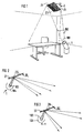
- FIG. 1 an office space with a workplace is shown schematically, a projector light 1 is placed on the side of the room floor. Thrower lights of this type are known per se. For geometric reasons, they have a light source that is as punctiform as possible and is surrounded by a secondary reflector. This directs the light emitted by the light source in a light bundle through the light exit opening 101 of the projector lamp 1 upwards against the ceiling. If the beam angle of the beam of the projector lamp 1 z. B. adjustable by shifting the position of a lamp as a light source relative to a reflector surrounding the lamp, different lighting effects can also be achieved. A narrow beam of light acts as "hard” light, while another beam of light gives “soft” light.
- a main reflector 2 is arranged in the light cone of the projector lamp 1, which is only illustrated by two edge rays 102 for reasons of clarity.
- this main reflector 2 in this exemplary embodiment consists of four partial reflectors 21 to 24, which - as will be explained later - are each individually rotatable or tiltable about the two axes of their flat base area.
- these partial reflectors 21 to 24 are merely indicated that they have a plurality of local reflector elements 26 and 28 on their surface facing the space, which are present in the individual partial reflectors 21, 22 , 23 and 24 can be designed differently and thus cause a different scattering characteristic.
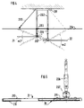
- FIGS. 2 and 3 This is illustrated schematically in FIGS. 2 and 3.
- the projector lamp 1 is illustrated by a point light source 103, which is surrounded by a secondary reflector 104.
- a partial reflector z. B. 21 and 22 shown in side view.
- These partial reflectors have local, alternatively concave or convex reflector elements 26 and 28 in this exemplary embodiment, in the form of regularly arranged spherical-spherical facets, which are shown in FIGS. 2 and 3 with clearly different radii R1 and R2.
- FIG. 4 now shows a side view of the structural design of such a main reflector 1.
- the reflector arrangement has a fastening disc 201, which, as indicated, is designed to be screwable to the ceiling is.
- the fastening disc 201 carries on its underside for each of the partial reflectors 21 to 24 a round rod 202, which is fixed on the one hand, for example, via an end thread on the fastening disc 201 and is pushed through a stiffening plate 203 at its other end.
- a protruding anti-glare disc 204 is pushed from below, which is fixed to the fastening disc 201 by means of guy ropes 205 (only one of these guy cables 205 is shown in detail in FIG. 4).
- a bearing pin 206 is fixed via a screw thread.
- this bearing pin is designed in two parts with an internal screw connection and thus its length can be adjusted.
- a ball joint 207 is fixed to each of the bearing bolts 206, which in turn each one of the partial reflectors z. B. carries 21 or 22.
- the partial reflectors 21 and 22 can each be pivoted in the plane of the drawing via this ball joint 207, but they are also arranged to be tiltable about an axis in the plane of the drawing.
- This rotatable mounting is indicated in FIG. 4 by maximum swivel angles ⁇ 1 and ⁇ 2, which result from a corresponding adjustment of the bearing bolts 206.
- each partial reflector 21 has a frame 210 which is bent on its four sides, the base plate of which is fixed to the ball joint 207 by means of a stiffening angle 211.
- the actual reflector surface of each partial reflector z. B. 21 consists of a plate with chamfers on all four sides, which is inserted into the frame 210 as far as it will go.
- This plate is made of high-gloss mirror material and has the embossed, pimpled local reflector elements in its base, e.g. B. 26, which are designed as spherical caps with a corresponding curvature, for example radius of curvature R1.
- the described configuration of exemplary embodiments of the invention shows that it is possible with any combination of differently faceted partial reflectors, the number of which does not necessarily have to be limited to four, to create the conditions for optimized lighting technology for solving different lighting tasks in an interior. Since it is possible to distribute the light emitted by a projector luminaire in partial luminous fluxes so that it is closely bundled and thus space-oriented as well as having a relatively wide distribution over larger areas of the illuminated interior, additional lighting sources for general lighting of the room can also be dispensed with in this lighting system. In general, to supplement the room lighting, the direct part of the lighting in the usage plane is supplemented by an indirect part via ceiling lighting.
- this lighting system has the advantage that individual points in the illuminated usage plane receive light from a large number of local reflector elements of the main reflector. This not only means greater uniformity of the illuminance in the individual areas of the user plane that are to be distinguished from one another, but also reduces the risk of reflective glare at a workplace.
- the arrangement of the mirror / projector system related to the workstation (s) can also contribute.
- the projector lamp installed close to the floor can be arranged in the room so that it does not bother the user. From the geometry of the lighting system it follows that the light outlet opening of the projector lamp has a sufficiently low luminance in the direction of a viewer despite a high luminous flux, which then even allows the projector lamp to be located directly next to workplaces or even to be integrated into work furniture. After all, this lighting system also offers the flexibility to provide it with an optically appealing design and thus to fit architecturally into a room furniture. The lighting system described thus also specifically takes into account the requirements of modern workplaces for lighting technology. A distinction must be made between pure desk work and VDU work, which require different illuminance levels, which in this case can be achieved using differently faceted partial reflectors.
- the described anti-glare disc which is arranged between the main reflector and the ceiling, is an additional, optically effective aid which serves to avoid strong differences in luminance of the ceiling in the vicinity of the main reflector.
- this cover plate is made of a translucent material that absorbs as little light as possible, for example a PMMA plastic with a non-reflecting surface, in order to use the light component that passes through as a supplement to indirect general lighting.
Landscapes
- Engineering & Computer Science (AREA)
- General Engineering & Computer Science (AREA)
- Non-Portable Lighting Devices Or Systems Thereof (AREA)
Priority Applications (1)
| Application Number | Priority Date | Filing Date | Title |
|---|---|---|---|
| EP95104887A EP0735311A1 (fr) | 1995-03-31 | 1995-03-31 | Système d'éclairage intérieur |
Applications Claiming Priority (1)
| Application Number | Priority Date | Filing Date | Title |
|---|---|---|---|
| EP95104887A EP0735311A1 (fr) | 1995-03-31 | 1995-03-31 | Système d'éclairage intérieur |
Publications (1)
| Publication Number | Publication Date |
|---|---|
| EP0735311A1 true EP0735311A1 (fr) | 1996-10-02 |
Family
ID=8219150
Family Applications (1)
| Application Number | Title | Priority Date | Filing Date |
|---|---|---|---|
| EP95104887A Ceased EP0735311A1 (fr) | 1995-03-31 | 1995-03-31 | Système d'éclairage intérieur |
Country Status (1)
| Country | Link |
|---|---|
| EP (1) | EP0735311A1 (fr) |
Cited By (16)
| Publication number | Priority date | Publication date | Assignee | Title |
|---|---|---|---|---|
| EP0836046A1 (fr) * | 1996-10-02 | 1998-04-15 | Siemens Beleuchtungstechnik GmbH & Co. KG | Dispositif d'éclairage extérieur à éclairage indirect |
| DE19821721A1 (de) * | 1998-05-14 | 1999-11-18 | Siteco Beleuchtungstech Gmbh | Sekundärstrahl-Arbeitsplatzleuchte |
| EP1411294A2 (fr) | 2002-10-15 | 2004-04-21 | Siteco Beleuchtungstechnik GmbH | Réflecteur avec une surface structurée et luminaire ou système d'éclairage indirect comprenant un tel réflecteur |
| WO2005071310A1 (fr) * | 2004-01-21 | 2005-08-04 | Fresnel Optics Gmbh | Dispositif pour eclairer de grandes surfaces de maniere homogene ou predeterminable |
| DE102004026160A1 (de) * | 2004-05-28 | 2005-12-22 | Siteco Beleuchtungstechnik Gmbh | Beleuchtungssystem zur Erzeugung einer variablen Lichtverteilung |
| EP1355184B1 (fr) * | 2002-04-18 | 2007-09-05 | Peter Dr. Graf | Réflexion optique par un "système intégré d'éléments-micro de réflexion" |
| WO2009007927A1 (fr) * | 2007-07-11 | 2009-01-15 | Koninklijke Philips Electronics N.V. | Procédé d'éclairage d'au moins une partie d'un espace et système d'éclairage destiné à être utilisé dans ce procédé |
| EP2264362A1 (fr) | 2006-03-21 | 2010-12-22 | Siteco Beleuchtungstechnik GmbH | Phares DEL et système d'éclairage doté de tels phares |
| CN102997187A (zh) * | 2011-09-14 | 2013-03-27 | 湖南明和光电设备有限公司 | 多角度反射并旋转成图案的led灯 |
| WO2013102862A1 (fr) * | 2012-01-05 | 2013-07-11 | Koninklijke Philips Electronics N.V. | Système d'éclairage |
| WO2015087116A1 (fr) | 2013-12-13 | 2015-06-18 | Dmy Mühendi̇sli̇k Elektri̇k Maki̇ne İnşaat Ve Bi̇li̇şi̇m San. Ti̇c. Ltd. Şti̇. | Réflecteur pour éclairage |
| WO2016134732A1 (fr) * | 2015-02-23 | 2016-09-01 | Coelux S.R.L. | Système d'éclairage de siège |
| EP3276255A1 (fr) * | 2016-07-27 | 2018-01-31 | Regent Beleuchtungskörper AG | Système d'éclairage |
| CH712751A1 (de) * | 2016-07-27 | 2018-01-31 | Regent Beleuchtungskörper Ag | Beleuchtungssystem. |
| US10088125B2 (en) | 2015-02-23 | 2018-10-02 | Coelux S.R.L. | Illumination system for optically widened perception |
| US10544919B2 (en) | 2016-09-22 | 2020-01-28 | Signify Holding B.V | Optical arrangement, lighting system and illumination method |
Citations (4)
| Publication number | Priority date | Publication date | Assignee | Title |
|---|---|---|---|---|
| FR676224A (fr) * | 1929-06-05 | 1930-02-20 | Nouveau procédé d'éclairage indirect pour intérieurs | |
| DE8526505U1 (de) * | 1985-09-17 | 1985-10-24 | VH Lichttechnische Spezial-Geräte Handel Jürgen von Hagen, 5300 Bonn | Vorrichtung zur kombinierten oder wahlweisen indirekten und lichtgelenkten Raumbeleuchtung |
| EP0479042A2 (fr) * | 1990-10-04 | 1992-04-08 | Christian Bartenbach | Dispositif d'éclairage |
| DE4109189A1 (de) * | 1991-03-16 | 1992-09-17 | Joachim Dittmann | Einrichtung zur indirekten beleuchtung |
-
1995
- 1995-03-31 EP EP95104887A patent/EP0735311A1/fr not_active Ceased
Patent Citations (4)
| Publication number | Priority date | Publication date | Assignee | Title |
|---|---|---|---|---|
| FR676224A (fr) * | 1929-06-05 | 1930-02-20 | Nouveau procédé d'éclairage indirect pour intérieurs | |
| DE8526505U1 (de) * | 1985-09-17 | 1985-10-24 | VH Lichttechnische Spezial-Geräte Handel Jürgen von Hagen, 5300 Bonn | Vorrichtung zur kombinierten oder wahlweisen indirekten und lichtgelenkten Raumbeleuchtung |
| EP0479042A2 (fr) * | 1990-10-04 | 1992-04-08 | Christian Bartenbach | Dispositif d'éclairage |
| DE4109189A1 (de) * | 1991-03-16 | 1992-09-17 | Joachim Dittmann | Einrichtung zur indirekten beleuchtung |
Cited By (20)
| Publication number | Priority date | Publication date | Assignee | Title |
|---|---|---|---|---|
| EP0836046A1 (fr) * | 1996-10-02 | 1998-04-15 | Siemens Beleuchtungstechnik GmbH & Co. KG | Dispositif d'éclairage extérieur à éclairage indirect |
| DE19821721A1 (de) * | 1998-05-14 | 1999-11-18 | Siteco Beleuchtungstech Gmbh | Sekundärstrahl-Arbeitsplatzleuchte |
| DE19821721C2 (de) * | 1998-05-14 | 2000-08-03 | Siteco Beleuchtungstech Gmbh | Standleuchte für Innenräume |
| EP1355184B1 (fr) * | 2002-04-18 | 2007-09-05 | Peter Dr. Graf | Réflexion optique par un "système intégré d'éléments-micro de réflexion" |
| EP1411294A2 (fr) | 2002-10-15 | 2004-04-21 | Siteco Beleuchtungstechnik GmbH | Réflecteur avec une surface structurée et luminaire ou système d'éclairage indirect comprenant un tel réflecteur |
| WO2005071310A1 (fr) * | 2004-01-21 | 2005-08-04 | Fresnel Optics Gmbh | Dispositif pour eclairer de grandes surfaces de maniere homogene ou predeterminable |
| DE102004026160B4 (de) * | 2004-05-28 | 2015-10-22 | Siteco Beleuchtungstechnik Gmbh | Beleuchtungssystem zur Erzeugung einer variablen Lichtverteilung |
| DE102004026160A1 (de) * | 2004-05-28 | 2005-12-22 | Siteco Beleuchtungstechnik Gmbh | Beleuchtungssystem zur Erzeugung einer variablen Lichtverteilung |
| EP2264362A1 (fr) | 2006-03-21 | 2010-12-22 | Siteco Beleuchtungstechnik GmbH | Phares DEL et système d'éclairage doté de tels phares |
| EP2264362B1 (fr) | 2006-03-21 | 2020-07-29 | SITECO GmbH | Phares DEL et système d'éclairage doté de tels phares |
| WO2009007927A1 (fr) * | 2007-07-11 | 2009-01-15 | Koninklijke Philips Electronics N.V. | Procédé d'éclairage d'au moins une partie d'un espace et système d'éclairage destiné à être utilisé dans ce procédé |
| CN102997187A (zh) * | 2011-09-14 | 2013-03-27 | 湖南明和光电设备有限公司 | 多角度反射并旋转成图案的led灯 |
| WO2013102862A1 (fr) * | 2012-01-05 | 2013-07-11 | Koninklijke Philips Electronics N.V. | Système d'éclairage |
| WO2015087116A1 (fr) | 2013-12-13 | 2015-06-18 | Dmy Mühendi̇sli̇k Elektri̇k Maki̇ne İnşaat Ve Bi̇li̇şi̇m San. Ti̇c. Ltd. Şti̇. | Réflecteur pour éclairage |
| WO2016134732A1 (fr) * | 2015-02-23 | 2016-09-01 | Coelux S.R.L. | Système d'éclairage de siège |
| US10088125B2 (en) | 2015-02-23 | 2018-10-02 | Coelux S.R.L. | Illumination system for optically widened perception |
| US10427599B2 (en) | 2015-02-23 | 2019-10-01 | Coelux S.R.L. | Seat illuminating system |
| EP3276255A1 (fr) * | 2016-07-27 | 2018-01-31 | Regent Beleuchtungskörper AG | Système d'éclairage |
| CH712751A1 (de) * | 2016-07-27 | 2018-01-31 | Regent Beleuchtungskörper Ag | Beleuchtungssystem. |
| US10544919B2 (en) | 2016-09-22 | 2020-01-28 | Signify Holding B.V | Optical arrangement, lighting system and illumination method |
Similar Documents
| Publication | Publication Date | Title |
|---|---|---|
| EP1632713B1 (fr) | Projecteur pour illuminer des surfaces d'un édifice | |
| EP2678603B1 (fr) | Dispositif d'éclairage | |
| EP0735311A1 (fr) | Système d'éclairage intérieur | |
| DE10360943A1 (de) | Beleuchtungseinrichtung | |
| DE2925456A1 (de) | Beleuchtungskoerper fuer strassenbeleuchtung | |
| EP1077344A2 (fr) | Lampe | |
| EP3199869B1 (fr) | Dispositif d'éclairage | |
| CH627252A5 (en) | Indirect ceiling luminaire for an area to be illuminated | |
| EP2264362B1 (fr) | Phares DEL et système d'éclairage doté de tels phares | |
| EP1843086A1 (fr) | Lampe à réflecteur | |
| EP0638764B2 (fr) | Lampadaire à éclairage principalement direct | |
| DE10252724A1 (de) | Verlichtingstoestel | |
| EP3865761B1 (fr) | Luminaire à fonction combinée de luminaire insert et de spot | |
| DE10011378A1 (de) | Hohllichtleiterleuchte mit indirekter Lichtabstrahlung | |
| EP1232363B2 (fr) | Ecran transparent anti-eblouissement pour lampe | |
| WO1987006995A1 (fr) | Lampe | |
| DE102004026160B4 (de) | Beleuchtungssystem zur Erzeugung einer variablen Lichtverteilung | |
| EP0836046B1 (fr) | Dispositif d'éclairage extérieur à éclairage indirect | |
| AT412901B (de) | Leuchte | |
| EP0813026A2 (fr) | Dispositif d'éclairage | |
| DE10213536B4 (de) | Sekundärbeleuchtungssystem sowie Leuchte mit einem solchen Sekundärbeleuchtungssystem | |
| EP3919808B1 (fr) | Luminaire | |
| DE10045028A1 (de) | Beleuchtungsanlage zur Simulation des Sonnenlichts | |
| DE19819223B4 (de) | Sekundärstrahl-Beleuchtungssystem | |
| WO2001065170A1 (fr) | Pylone d'eclairage |
Legal Events
| Date | Code | Title | Description |
|---|---|---|---|
| PUAI | Public reference made under article 153(3) epc to a published international application that has entered the european phase |
Free format text: ORIGINAL CODE: 0009012 |
|
| AK | Designated contracting states |
Kind code of ref document: A1 Designated state(s): AT CH DE GB IT LI NL |
|
| 17P | Request for examination filed |
Effective date: 19970320 |
|
| RAP1 | Party data changed (applicant data changed or rights of an application transferred) |
Owner name: SIEMENS BELEUCHTUNGSTECHNIK GMBH & CO. KG |
|
| RAP1 | Party data changed (applicant data changed or rights of an application transferred) |
Owner name: SITECO BELEUCHTUNGSTECHNIK GMBH |
|
| 17Q | First examination report despatched |
Effective date: 20001122 |
|
| STAA | Information on the status of an ep patent application or granted ep patent |
Free format text: STATUS: THE APPLICATION HAS BEEN REFUSED |
|
| 18R | Application refused |
Effective date: 20030222 |