EP0734111B1 - Photovoltaische Hochspannungsanlage mit individuellen Speichermitteln - Google Patents
Photovoltaische Hochspannungsanlage mit individuellen Speichermitteln Download PDFInfo
- Publication number
- EP0734111B1 EP0734111B1 EP96400610A EP96400610A EP0734111B1 EP 0734111 B1 EP0734111 B1 EP 0734111B1 EP 96400610 A EP96400610 A EP 96400610A EP 96400610 A EP96400610 A EP 96400610A EP 0734111 B1 EP0734111 B1 EP 0734111B1
- Authority
- EP
- European Patent Office
- Prior art keywords
- voltage
- converters
- batteries
- volts
- station according
- Prior art date
- Legal status (The legal status is an assumption and is not a legal conclusion. Google has not performed a legal analysis and makes no representation as to the accuracy of the status listed.)
- Expired - Lifetime
Links
Images


Classifications
-
- H—ELECTRICITY
- H02—GENERATION; CONVERSION OR DISTRIBUTION OF ELECTRIC POWER
- H02J—CIRCUIT ARRANGEMENTS OR SYSTEMS FOR SUPPLYING OR DISTRIBUTING ELECTRIC POWER; SYSTEMS FOR STORING ELECTRIC ENERGY
- H02J7/00—Circuit arrangements for charging or depolarising batteries or for supplying loads from batteries
- H02J7/34—Parallel operation in networks using both storage and other dc sources, e.g. providing buffering
- H02J7/35—Parallel operation in networks using both storage and other dc sources, e.g. providing buffering with light sensitive cells
-
- G—PHYSICS
- G05—CONTROLLING; REGULATING
- G05F—SYSTEMS FOR REGULATING ELECTRIC OR MAGNETIC VARIABLES
- G05F1/00—Automatic systems in which deviations of an electric quantity from one or more predetermined values are detected at the output of the system and fed back to a device within the system to restore the detected quantity to its predetermined value or values, i.e. retroactive systems
- G05F1/66—Regulating electric power
- G05F1/67—Regulating electric power to the maximum power available from a generator, e.g. from solar cell
-
- Y—GENERAL TAGGING OF NEW TECHNOLOGICAL DEVELOPMENTS; GENERAL TAGGING OF CROSS-SECTIONAL TECHNOLOGIES SPANNING OVER SEVERAL SECTIONS OF THE IPC; TECHNICAL SUBJECTS COVERED BY FORMER USPC CROSS-REFERENCE ART COLLECTIONS [XRACs] AND DIGESTS
- Y02—TECHNOLOGIES OR APPLICATIONS FOR MITIGATION OR ADAPTATION AGAINST CLIMATE CHANGE
- Y02B—CLIMATE CHANGE MITIGATION TECHNOLOGIES RELATED TO BUILDINGS, e.g. HOUSING, HOUSE APPLIANCES OR RELATED END-USER APPLICATIONS
- Y02B10/00—Integration of renewable energy sources in buildings
- Y02B10/10—Photovoltaic [PV]
-
- Y—GENERAL TAGGING OF NEW TECHNOLOGICAL DEVELOPMENTS; GENERAL TAGGING OF CROSS-SECTIONAL TECHNOLOGIES SPANNING OVER SEVERAL SECTIONS OF THE IPC; TECHNICAL SUBJECTS COVERED BY FORMER USPC CROSS-REFERENCE ART COLLECTIONS [XRACs] AND DIGESTS
- Y02—TECHNOLOGIES OR APPLICATIONS FOR MITIGATION OR ADAPTATION AGAINST CLIMATE CHANGE
- Y02E—REDUCTION OF GREENHOUSE GAS [GHG] EMISSIONS, RELATED TO ENERGY GENERATION, TRANSMISSION OR DISTRIBUTION
- Y02E10/00—Energy generation through renewable energy sources
- Y02E10/50—Photovoltaic [PV] energy
- Y02E10/56—Power conversion systems, e.g. maximum power point trackers
-
- Y—GENERAL TAGGING OF NEW TECHNOLOGICAL DEVELOPMENTS; GENERAL TAGGING OF CROSS-SECTIONAL TECHNOLOGIES SPANNING OVER SEVERAL SECTIONS OF THE IPC; TECHNICAL SUBJECTS COVERED BY FORMER USPC CROSS-REFERENCE ART COLLECTIONS [XRACs] AND DIGESTS
- Y10—TECHNICAL SUBJECTS COVERED BY FORMER USPC
- Y10S—TECHNICAL SUBJECTS COVERED BY FORMER USPC CROSS-REFERENCE ART COLLECTIONS [XRACs] AND DIGESTS
- Y10S136/00—Batteries: thermoelectric and photoelectric
- Y10S136/291—Applications
- Y10S136/293—Circuits
-
- Y—GENERAL TAGGING OF NEW TECHNOLOGICAL DEVELOPMENTS; GENERAL TAGGING OF CROSS-SECTIONAL TECHNOLOGIES SPANNING OVER SEVERAL SECTIONS OF THE IPC; TECHNICAL SUBJECTS COVERED BY FORMER USPC CROSS-REFERENCE ART COLLECTIONS [XRACs] AND DIGESTS
- Y10—TECHNICAL SUBJECTS COVERED BY FORMER USPC
- Y10S—TECHNICAL SUBJECTS COVERED BY FORMER USPC CROSS-REFERENCE ART COLLECTIONS [XRACs] AND DIGESTS
- Y10S320/00—Electricity: battery or capacitor charging or discharging
- Y10S320/13—Fault detection
-
- Y—GENERAL TAGGING OF NEW TECHNOLOGICAL DEVELOPMENTS; GENERAL TAGGING OF CROSS-SECTIONAL TECHNOLOGIES SPANNING OVER SEVERAL SECTIONS OF THE IPC; TECHNICAL SUBJECTS COVERED BY FORMER USPC CROSS-REFERENCE ART COLLECTIONS [XRACs] AND DIGESTS
- Y10—TECHNICAL SUBJECTS COVERED BY FORMER USPC
- Y10S—TECHNICAL SUBJECTS COVERED BY FORMER USPC CROSS-REFERENCE ART COLLECTIONS [XRACs] AND DIGESTS
- Y10S323/00—Electricity: power supply or regulation systems
- Y10S323/906—Solar cell systems
Definitions
- the present invention relates to a high voltage photovoltaic energy station with custom storage.
- the technical field concerned by the invention is that of the supply of electrical energy in an isolated site, via a photovoltaic type station.
- some solar stations associate photovoltaic solar modules 10 with a unit voltage of 12 Volts in series / parallel groups, for example n columns B1 . Bn of four modules, in order to obtain a power adapted to needs, and a battery 11 (24 or 48 volts) corresponding to a capacity adapted to the desired autonomy, to feed a load (use) directly continuous.
- the charge of the battery 11 is controlled by a voltage regulator 12 placed between the modules 10 and the storage battery 11.
- the use 24 or 48 VDC
- the use regulator 14 is connected to the storage battery through a battery.
- use regulator 14 as shown in Figure 1. In this figure is also illustrated the solar radiation 13.
- some stations are designed differently. They consist of a storage of the double battery type: one 20 is connected to the use, while the other 21 is recharged on the solar panels 10. The permutation is done at the end of discharge of the battery connected to the use.
- the voltages of the storage batteries are identical to those of the stations defined above, the use is also supplied with low voltage and direct current type (24/48 volts).
- other stations more particularly intended to supply an AC load comprise a battery 25 of the high voltage type (110 or 220 volts DC) charged by a combination of photovoltaic solar modules 10 in series / parallel and an inverter (DC / AC) 26 powered behind this storage battery that transforms the direct current into alternating current for use (110/220 AC).
- a regulator 27 controls the charge of the battery. But this type of station is not or very little used for the powers concerned by the invention.
- the 48-volt DC source that is delivered and routed to use has to be converted into all these different voltages by means of converters, these converters being integrated into the systems themselves. This results in a significant heat release at the level of sensitive equipment. Moreover, the different voltages delivered at the output do not benefit from customized storage adapted to the needs on each voltage (in general the same intensity is not requested on each voltage used in a given system).
- the low voltage transport is the seat of significant voltage drops, which requires the use of connection cables. an important section so as to limit the losses due to the resistance of the connecting cable and the distance.
- the storage is done at one time at the level of the inverter.
- a voltage regulator for charging the battery is required.
- the efficiency of the inverter is not perfect. This one is generally not duplicated because of its high cost, which makes the station unreliable and without redundancy, and which introduces energy losses in the circuit.
- the connection to the use is made in AC high voltage. Voltage drops are limited and the section of the connecting cables is weaker. But for use in multiple DC voltages, essential to current modern equipment, it is generally necessary to introduce a 220 volts AC power supply that will transform the 220 volts AC into DC multisources. Such a power supply is generally integrated into the equipment to be powered. Again, no customization of different tensions is possible. In addition the heat release of these power supplies is not without inconvenience on the proper operation of these sets.
- the prior art document [4] describes an apparatus for controlling the use of electrical energy supplied by an irregular source of energy, for example a set of photoelectric cells, which supplies energy to a load and to a storage battery.
- the photovoltaic solar modules are unit voltage modules, for example 55 volts.
- the main storage consists of 110 elements of nominal 2 volts and capacity depending on the load and the desired autonomy in operation without sunshine.
- the different batteries of the main storage device and the so-called personalized storage device are either stationary lead type with high electrolyte reserve and possibly with electrolyte stirring system, either sealed or nickel-cadmium.
- At least one passage diode is disposed on each accumulator battery element so as to ensure continuity of operation in the event of breakage of an element.
- the conversion device comprises DC / DC converters, arranged in parallel or in series, starting from 220 volts DC to provide the voltages necessary for use.
- the batteries of the so-called personalized storage device are either of the stationary lead-acid solar battery type with a high electrolyte reserve, or of the gas-tight type, or of the cadmium / nickel type batteries.
- the charging and the maintenance of these batteries are obtained thanks to converters DC / DC conversion device whose output voltage is adjustable from 20% to 60%,
- the conversion device comprises an original converter equipped with an automatic charge / maintenance passage system corresponding to a change of voltage applied to the accumulator battery elements.
- a filter circuit, regulation for ensuring the regulation of the voltage on the use is disposed at the output of the conversion device and the so-called personalized storage device.
- a differential amplifier amplifies the difference between the reference voltage, obtained from a zener diode and the measured voltage at the output of the conversion device / storage device assembly, which is customized, the reference voltage being brought to zero by a microprocessor or a voltage presence detector thus inhibiting the action of the regulator. In case of battery discharge, it is this last circuit which regulates the voltage in discharge, while the microprocessor limits the duration.
- the conversion device comprises DC / DC converters which are all connected in parallel, the capacity of the assembly taking into account the current permanent use, as well as the charging current of storage batteries.
- the conversion device comprises converters assigned to the only charge of the batteries of the so-called personalized storage device.
- the output voltage of the converters is set independently of the output voltage of the on-line converters on the use, the redundancy of the converters being calculated on the sole needs of the use, the charging circuit of the batteries being already considered as a circuit rescue.
- the telecommunications equipment is totally separated from the energy equipment, a completely closed and thermally insulated enclosure being then provided.
- the originality of the station according to the invention is to operate in high voltage and to propose a system for storing energy customized for each type of use.
- the good performance of the assembly associated with the absence of significant heat, as well as the "natural" protection against theft of the solar panels (due to the operation under unusable voltage for the usual domestic needs) makes a station especially for isolated sites in hot and very sunny climates.
- Such a station makes it possible to optimize the sizing of both the peak power (photovoltaic solar modules) and the battery capacity. Indeed, so-called “custom” storage makes it possible to assign to each operating voltage the necessary power (converters and associated batteries).
- main storage battery is common to all operating voltages, and a so-called custom or distributed storage battery exists for each operating voltage.
- a cumulative and configurable autonomy (we can also speak of modular) is assigned to each of these storages thus offering the user numerous possibilities of adaptation to changes and extensions of loads.
- a priority or progressive recharge can be made at one or more storage batteries (adaptation of the dimensioning according to the so-called "priority" load).
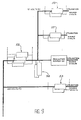
- FIG. 4 shows the general principle of the high-voltage photovoltaic energy station with personalized storage according to the invention.
- the solar photovoltaic modules 10 feed on the one hand the various DC / DC converters and on the other hand charge the main battery (220 volts DC) through the high voltage charge controller. If necessary the DC / DC converters can also power the use and recharge the various associated batteries. During normal operation, these so-called customized batteries at each source are simply maintained in their fully charged state.
- non-sunshine period night or period of low or no sunshine
- the main battery provides amperes hours needed to power the DC / DC converters. If the period of non-sunshine is greater than the so-called battery life time fixed by the calculation of the initial sizing, then the main battery disconnects (role of the high voltage charge controller) and it is the so-called custom batteries that take the relieves by ensuring the supply of amperes hours to use. If this second battery run time is longer than the initial sizing time, a safety disconnects these batteries to protect them from deep discharge.
- the main battery When the sunshine returns, the main battery is automatically reconnected and recharged; in parallel, the converters are also powered; they automatically switch to the charging position and recharge the associated batteries while feeding the use.
- a variant represented in FIG. 8 could consist in customizing certain converters 58 to assign them a more specific role of charger (higher charge voltage than on the use). This is a function that is well known on rectifier / charger systems in 48 volts in particular.
- the high voltage regulator As well as the different converters, resume their normal operating / maintenance voltages.
- the solar generator The solar generator:
- Custom DC / DC converters Custom DC / DC converters :
- Source 2 V / 75 A Capacity for 5 days (C / 120) of 9,000 Ah, in C / 10: 6,430 Ah
- Source 5 V / 120 A Capacity for 5 days (C / 120) of 14 4000 Ah
- Source 12 V / 10 A Capacity for 5 days (C / 120) of 1200 Ah
- Source 28 V / 4 A Capacity for 5 days (C / 120) of 480 Ah, in C / 10: 345 Ah
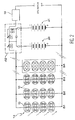
- Figure 7 corresponds to a first configuration in which the converter is originally equipped with an automatic system of passage charge / maintenance corresponding to a voltage change applied to the elements of accumulator batteries.
- a filter circuit At the output of the converter and personalized battery assembly, there is a filter circuit, regulation for regulating the voltage on the use. Indeed, in custom battery operation, the voltage of this battery will vary throughout its charge / discharge cycle, while (for example) we must ensure a supply of 5.15 volts constant on the source (5 volts / 120A) hence the need to provide a control circuit.
- This regulation is well controlled by those skilled in the art.
- the embodiment consisting of several MOS transistors whose transductance characteristic is considered in order to vary the drain-source voltage.
- a differential amplifier can amplify the difference between the reference voltage obtained from a zener diode and the voltage measured at the output of the battery / converter.
- the reference voltage can be brought to zero by a microprocessor or by a voltage presence detector thus inhibiting the action of the regulator. In case of battery discharge it is this last circuit which regulates the voltage in discharge, while the microprocessor limits the duration.
- the DC / DC converters are all connected in parallel.
- the capacity of the assembly must take into account the permanent current proper to the use, plus the charging current of the storage batteries.
- the cooldown is an element of calculation for the sizing of the converters. In the example in question, a charging period of ten days is adopted.
- the unit power of each converter can be determined according to a given size or standardization.
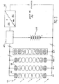
- FIG. 8 A second configuration is to assign converters to the only load of custom batteries. This solution is shown in FIG. 8. In this FIG. 8, the same references as in FIG. 7 are shown. In addition, loader converters 58 are shown.
- the output voltage of the converters can be adjusted independently of the output voltage of the on-line converters on the use.
- the redundancy of the converters is calculated on the sole needs of the use, the charging circuit of the batteries being already considered as a backup circuit. It follows a gain in equipment. Moreover one can consider a cut of the load converter when the associated battery is charged, thereby saving on the overall consumption of the station.
- battery packs of type 6 or 12 volts units can be used (additional space saving).
- the autonomy of these sources is not necessarily the same as on the other sources. For example, if these voltages serve for example remote alarm return, once the terminal system informed of the alarm it is no longer necessary to maintain its local power supply. This is how saving and saving of space can be envisaged on the personalized storage of this source (not taken into account in the example). This is to explain the benefits of this type of energy station.
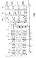
- Another variant of the invention consists in storing the energy only on one or two customized batteries and ensuring the supply of sources by converters adapted to storage sources as shown in FIG. 9, the references used being those used on Figure 8.
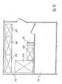
- the invention is characterized in that the telecommunications equipment is totally separate from the energy equipment.
- the heat release characteristic of telecommunications equipment is minimal, no ventilation is required, a fully enclosed and thermally insulated enclosure is provided. This arrangement avoids the well known problems under equatorial climate: humidity, heat, penetration of dust and insects, rodents ...
- In 71 is represented the room of telecommunications equipment.
Claims (16)
- Photovoltaische Energiestation hoher Spannung mit doppelter Speicherung, die Folgendes aufweist:- mehrere photovoltaische Solarmodule (10), die Module mit Einheitsspannung in einer Serien-/Parallelschaltung sind,- eine Hauptspeichervorrichtung für Hochspannung (32), die von einer Akkumulatoren-Batterie gebildet wird;- einen Ladungsregler (31) für die Hauptspeichervorrichtung (32);dadurch gekennzeichnet, dass sie weiter Folgendes aufweist:- eine anwendungsspezifische Speichervorrichtung (33), die mindestens eine anwendungsspezifische Speicherbatterie aufweist, die es ermöglicht, die für eine oder mehrere Nutzspannungen notwendige Leistung zuzuteilen;- eine Umwandlungsvorrichtung (34) zwischen der Hauptspeichervorrichtung und der anwendungsspezifischen Speichervorrichtung;- eine Hochspannungsverbindung zwischen der Hauptspeichervorrichtung (32) und der Umwandlungsvorrichtung (34);- eine Regelvorrichtung (35) für jede Nutzspannung.
- Station nach Anspruch 1, dadurch gekennzeichnet, dass die photovoltaischen Solarmodule Module mit einer Mindesteinheitsspannung von 55 Volt sind.
- Station nach Anspruch 1, dadurch gekennzeichnet, dass die Hauptspeichervorrichtung (32) aus einer Batterie von in Reihe geschalteten Akkumulatoren besteht, deren Gesamtspannung mindestens 220 Volt beträgt und deren Kapazität von der Ladung und der gewünschten Autonomie im Betrieb ohne Sonneneinstrahlung abhängt.
- Station nach Anspruch 3, dadurch gekennzeichnet, dass die Batterien der Hauptspeichervorrichtung (32) und der anwendungsspezifischen Speichervorrichtung (33) vom stationären Blei-Typ mit großer Elektrolytreserve oder vom dichten Typ oder vom Cadmium-Nickel-Typ sind.
- Station nach Anspruch 3, dadurch gekennzeichnet, dass Durchgangsdioden (41) auf jedem Element (40) der Batterie von Akkumulatoren angeordnet sind, um eine Betriebskontinuität im Fall des Bruchs eines Elements zu gewährleisten.
- Station nach Anspruch 1, dadurch gekennzeichnet, dass die Umwandlungsvorrichtung (34) Gleichstrom/Gleichstrom-Wandler enthält, die parallel oder in Reihe geschaltet sind, ausgehend vom 220-Volt-Gleichstrom, um die Nutzspannungen zu liefern.
- Station nach Anspruch 1, dadurch gekennzeichnet, dass die anwendungsspezifische Speichervorrichtung (33) Batterien aufweist, die entweder vom Typ stationäre Blei-Solarbatterien mit großer Elektrolytreserve oder vom dichten Typ mit Rekombination von Gas oder Batterien vom Cadmium/Nickel-Typ sind, wobei das Aufladen und die Aufrechterhaltung der Spannung dieser Batterien mit Hilfe der Gleichstrom/Gleichstrom-Wandler erhalten werden, deren Ausgangsspannung von 20 % bis 60 % einstellbar ist.
- Station nach Anspruch 7, dadurch gekennzeichnet, dass die Umwandlungsvorrichtung einen mit einem automatischen System des Übergangs zwischen Ladung und Aufrechterhaltung versehenen Wandler aufweist, was einem Wechsel der an die Elemente der Akkumulatoren-Batterien angelegten Spannung entspricht.
- Station nach Anspruch 8, dadurch gekennzeichnet, dass sie eine Filterungs-/Regelungsschaltung aufweist, die dazu bestimmt ist, die Regelung der Nutzspannung zu gewährleisten und die am Ausgang der Umwandlungsvorrichtung (34) und der anwendungsspezifischen Speichervorrichtung (33) angeordnet ist.
- Station nach Anspruch 8, dadurch gekennzeichnet, dass sie einen Differentialverstärker aufweist, der die Differenz zwischen der in einer ZenerDiode erhaltenen Bezugsspannung und der am Ausgang der Einheit aus Umwandlungsvorrichtung (34) und anwendungsspezifischer Speichervorrichtung (33) gemessenen Spannung verstärkt, wobei die Bezugsspannung von einem Mikroprozessor oder von einem Detektor für das Vorhandensein von Spannung auf Null gebracht wird, wodurch die Einwirkung des Reglers verhindert wird.
- Station nach Anspruch 10, dadurch gekennzeichnet, dass die Umwandlungsvorrichtung DC/DC-Wandler in Serien-/Parallelschaltung aufweist, wobei die Kapazität der Einheit den der Nutzung eigenen Permanentstrom sowie den Aufladestrom für die Akkumulatoren-Batterien berücksichtigt.
- Station nach Anspruch 1, dadurch gekennzeichnet, dass die Umwandlungsvorrichtung Wandler aufweist, die nur zum Laden der Batterien der anwendungsspezifischen Speichervorrichtung (33) eingesetzt werden.
- Station nach Anspruch 12, dadurch gekennzeichnet, dass die Ausgangsspannung der Wandler unabhängig von der Ausgangsspannung der Wandler direkt an der Nutzung geregelt wird, wobei die Redundanz der Wandler nur für den Bedarf der Nutzung berechnet wird, wobei die Schaltung zum Laden der Batterien als eine Hilfsschaltung angesehen wird.
- Station nach Anspruch 1, dadurch gekennzeichnet, dass die Umwandlungsvorrichtung Wandler (34) aufweist, und dass die Regelungsvorrichtung anwendungsspezifische Regler (35) aufweist, wobei die Wandler (34), die anwendungsspezifischen Speicherbatterien (33) und die anwendungsspezifischen Regler (35) Elektronik- oder Informatikeinrichtungen versorgen.
- Station nach Anspruch 1, dadurch gekennzeichnet, dass sie Telekommunikationsgeräte aufweist, die vollständig von den Energieeinrichtungen getrennt sind, wobei ein vollständig geschlossener und wärmeisolierter Raum vorgesehen ist.
- Station nach Anspruch 1, dadurch gekennzeichnet, dass sie zwei Typen von anwendungsspezifischen Energiespeicherbatterien aufweist.
Applications Claiming Priority (2)
| Application Number | Priority Date | Filing Date | Title |
|---|---|---|---|
| FR9503490A FR2732170B1 (fr) | 1995-03-24 | 1995-03-24 | Station d'energie photovoltaique haute tension a stockage personnalise |
| FR9503490 | 1995-03-24 |
Publications (3)
| Publication Number | Publication Date |
|---|---|
| EP0734111A2 EP0734111A2 (de) | 1996-09-25 |
| EP0734111A3 EP0734111A3 (de) | 1996-11-13 |
| EP0734111B1 true EP0734111B1 (de) | 2006-07-05 |
Family
ID=9477397
Family Applications (1)
| Application Number | Title | Priority Date | Filing Date |
|---|---|---|---|
| EP96400610A Expired - Lifetime EP0734111B1 (de) | 1995-03-24 | 1996-03-22 | Photovoltaische Hochspannungsanlage mit individuellen Speichermitteln |
Country Status (4)
| Country | Link |
|---|---|
| US (1) | US5684385A (de) |
| EP (1) | EP0734111B1 (de) |
| DE (1) | DE69636317T2 (de) |
| FR (1) | FR2732170B1 (de) |
Cited By (1)
| Publication number | Priority date | Publication date | Assignee | Title |
|---|---|---|---|---|
| CN101764414A (zh) * | 2010-03-10 | 2010-06-30 | 江苏省电力设计院 | 基于四要素约束法的光伏电站并网容量优化控制方法 |
Families Citing this family (103)
| Publication number | Priority date | Publication date | Assignee | Title |
|---|---|---|---|---|
| JPH11251615A (ja) * | 1998-03-03 | 1999-09-17 | Canon Inc | 融雪機能付き太陽光発電システム |
| US6156967A (en) * | 1998-06-04 | 2000-12-05 | Tecstar Power Systems, Inc. | Modular glass covered solar cell array |
| US6188146B1 (en) * | 1998-05-21 | 2001-02-13 | Paris Michaels | Supplying power for communications devices |
| AU770832B2 (en) * | 1998-05-21 | 2004-03-04 | Paris Michaels | Supplying power for communications devices |
| US6278054B1 (en) | 1998-05-28 | 2001-08-21 | Tecstar Power Systems, Inc. | Solar cell having an integral monolithically grown bypass diode |
| US5959370A (en) * | 1998-07-15 | 1999-09-28 | Pardo; Herbert | Differential voltage battery DC power supply |
| US6103970A (en) | 1998-08-20 | 2000-08-15 | Tecstar Power Systems, Inc. | Solar cell having a front-mounted bypass diode |
| JP3809316B2 (ja) * | 1999-01-28 | 2006-08-16 | キヤノン株式会社 | 太陽光発電装置 |
| JP2000312019A (ja) * | 1999-02-25 | 2000-11-07 | Canon Inc | 太陽電池モジュールアレイ、太陽電池モジュールアレイの設置構造、太陽電池モジュールの設置方法及び太陽光発電システム |
| US6704626B1 (en) * | 1999-04-02 | 2004-03-09 | Herzog Contracting Corp. | Logistics system and method with position control |
| AU2001278046A1 (en) * | 2000-07-28 | 2002-02-13 | International Power Systems, Inc. | Dc to dc converter and power management system |
| US6583522B1 (en) * | 2000-09-27 | 2003-06-24 | Worldwater Corp. | Switchable multiple source power supply |
| WO2002086649A1 (en) * | 2001-04-20 | 2002-10-31 | Erik Kai Lund | Regulator device |
| US6686533B2 (en) | 2002-01-29 | 2004-02-03 | Israel Aircraft Industries Ltd. | System and method for converting solar energy to electricity |
| US7002302B2 (en) | 2002-10-07 | 2006-02-21 | Samsung Sdi Co., Ltd. | Flat panel display |
| EP1642355A4 (de) | 2003-05-28 | 2015-05-27 | Beacon Power Llc | Stromwandler für eine solartafel |
| US20050235864A1 (en) * | 2004-04-22 | 2005-10-27 | Herzog Contracting Corp. | Method for delivering replacement rail ties using GPS techniques |
| US7152347B2 (en) * | 2004-06-17 | 2006-12-26 | Herzog Contracting Corporation | Method and apparatus for applying railway ballast |
| TWI344258B (en) * | 2005-08-19 | 2011-06-21 | Delta Electronics Inc | Motor driving method and device thereof |
| US10693415B2 (en) | 2007-12-05 | 2020-06-23 | Solaredge Technologies Ltd. | Testing of a photovoltaic panel |
| US11881814B2 (en) | 2005-12-05 | 2024-01-23 | Solaredge Technologies Ltd. | Testing of a photovoltaic panel |
| WO2008046370A1 (de) * | 2006-10-19 | 2008-04-24 | Fpe Fischer Gmbh | Verfahren und schaltung zur überwachung von solar-panels auf diebstahl |
| US9130390B2 (en) * | 2006-11-27 | 2015-09-08 | David A. Besser | Power extractor detecting power and voltage changes |
| US9431828B2 (en) * | 2006-11-27 | 2016-08-30 | Xslent Energy Technologies | Multi-source, multi-load systems with a power extractor |
| US8013474B2 (en) * | 2006-11-27 | 2011-09-06 | Xslent Energy Technologies, Llc | System and apparatuses with multiple power extractors coupled to different power sources |
| US7960870B2 (en) * | 2006-11-27 | 2011-06-14 | Xslent Energy Technologies, Llc | Power extractor for impedance matching |
| US8319471B2 (en) | 2006-12-06 | 2012-11-27 | Solaredge, Ltd. | Battery power delivery module |
| US11569659B2 (en) | 2006-12-06 | 2023-01-31 | Solaredge Technologies Ltd. | Distributed power harvesting systems using DC power sources |
| US8013472B2 (en) | 2006-12-06 | 2011-09-06 | Solaredge, Ltd. | Method for distributed power harvesting using DC power sources |
| US11735910B2 (en) | 2006-12-06 | 2023-08-22 | Solaredge Technologies Ltd. | Distributed power system using direct current power sources |
| US11728768B2 (en) | 2006-12-06 | 2023-08-15 | Solaredge Technologies Ltd. | Pairing of components in a direct current distributed power generation system |
| US11296650B2 (en) | 2006-12-06 | 2022-04-05 | Solaredge Technologies Ltd. | System and method for protection during inverter shutdown in distributed power installations |
| US8473250B2 (en) | 2006-12-06 | 2013-06-25 | Solaredge, Ltd. | Monitoring of distributed power harvesting systems using DC power sources |
| US11855231B2 (en) | 2006-12-06 | 2023-12-26 | Solaredge Technologies Ltd. | Distributed power harvesting systems using DC power sources |
| US8384243B2 (en) | 2007-12-04 | 2013-02-26 | Solaredge Technologies Ltd. | Distributed power harvesting systems using DC power sources |
| US8618692B2 (en) | 2007-12-04 | 2013-12-31 | Solaredge Technologies Ltd. | Distributed power system using direct current power sources |
| US11687112B2 (en) | 2006-12-06 | 2023-06-27 | Solaredge Technologies Ltd. | Distributed power harvesting systems using DC power sources |
| US9130401B2 (en) | 2006-12-06 | 2015-09-08 | Solaredge Technologies Ltd. | Distributed power harvesting systems using DC power sources |
| US8947194B2 (en) | 2009-05-26 | 2015-02-03 | Solaredge Technologies Ltd. | Theft detection and prevention in a power generation system |
| US8816535B2 (en) | 2007-10-10 | 2014-08-26 | Solaredge Technologies, Ltd. | System and method for protection during inverter shutdown in distributed power installations |
| US9088178B2 (en) | 2006-12-06 | 2015-07-21 | Solaredge Technologies Ltd | Distributed power harvesting systems using DC power sources |
| US9112379B2 (en) | 2006-12-06 | 2015-08-18 | Solaredge Technologies Ltd. | Pairing of components in a direct current distributed power generation system |
| US8319483B2 (en) | 2007-08-06 | 2012-11-27 | Solaredge Technologies Ltd. | Digital average input current control in power converter |
| US8963369B2 (en) | 2007-12-04 | 2015-02-24 | Solaredge Technologies Ltd. | Distributed power harvesting systems using DC power sources |
| US11888387B2 (en) | 2006-12-06 | 2024-01-30 | Solaredge Technologies Ltd. | Safety mechanisms, wake up and shutdown methods in distributed power installations |
| US11309832B2 (en) | 2006-12-06 | 2022-04-19 | Solaredge Technologies Ltd. | Distributed power harvesting systems using DC power sources |
| US7679943B2 (en) * | 2007-01-08 | 2010-03-16 | Maxvision Corporation | Uninterruptable power supply |
| US7663342B2 (en) * | 2007-01-26 | 2010-02-16 | Solarbridge Technologies, Inc. | Apparatus, system, and method for controlling multiple power supplies |
| US8354818B2 (en) * | 2007-10-09 | 2013-01-15 | Ford Global Technologies, Llc | Solar charged hybrid power system |
| US7755916B2 (en) | 2007-10-11 | 2010-07-13 | Solarbridge Technologies, Inc. | Methods for minimizing double-frequency ripple power in single-phase power conditioners |
| US9291696B2 (en) | 2007-12-05 | 2016-03-22 | Solaredge Technologies Ltd. | Photovoltaic system power tracking method |
| US8049523B2 (en) | 2007-12-05 | 2011-11-01 | Solaredge Technologies Ltd. | Current sensing on a MOSFET |
| US11264947B2 (en) | 2007-12-05 | 2022-03-01 | Solaredge Technologies Ltd. | Testing of a photovoltaic panel |
| CN101933209B (zh) | 2007-12-05 | 2015-10-21 | 太阳能安吉有限公司 | 分布式电力装置中的安全机构、醒来和关闭方法 |
| EP2232690B1 (de) | 2007-12-05 | 2016-08-31 | Solaredge Technologies Ltd. | Parallel geschaltete umrichter |
| WO2009118682A2 (en) | 2008-03-24 | 2009-10-01 | Solaredge Technolgies Ltd. | Zero current switching |
| WO2009136358A1 (en) | 2008-05-05 | 2009-11-12 | Solaredge Technologies Ltd. | Direct current power combiner |
| US8088991B2 (en) * | 2008-07-25 | 2012-01-03 | Hewlett-Packard Development Company, L.P. | Three-terminal two-junction photovoltaic cells and method of use |
| US20100019578A1 (en) * | 2008-07-26 | 2010-01-28 | Semikron Elektronik Gmbh & Co. Kg | Power Converter for Solar Electrical Current Installations and Method for Controlling it |
| US20100259211A1 (en) * | 2009-04-08 | 2010-10-14 | Jen Yen Yen | Recharge battery safely chargeable with solar energy |
| US8279642B2 (en) | 2009-07-31 | 2012-10-02 | Solarbridge Technologies, Inc. | Apparatus for converting direct current to alternating current using an active filter to reduce double-frequency ripple power of bus waveform |
| US8462518B2 (en) | 2009-10-12 | 2013-06-11 | Solarbridge Technologies, Inc. | Power inverter docking system for photovoltaic modules |
| US8824178B1 (en) | 2009-12-31 | 2014-09-02 | Solarbridge Technologies, Inc. | Parallel power converter topology |
| FR2961035B1 (fr) * | 2010-06-04 | 2013-09-20 | Aeg Power Solutions Bv | Dispositif de connexion matricielle pour panneaux photovoltaiques et/ou eoliennes |
| US20130015805A1 (en) * | 2010-06-04 | 2013-01-17 | Triune Ip Llc | Energy storage element link and monitor |
| DE102010023262A1 (de) * | 2010-06-09 | 2011-12-15 | Danfoss Solar Inverters A/S | Solarkraftwerk mit erhöhter Lebensdauer |
| US8503200B2 (en) | 2010-10-11 | 2013-08-06 | Solarbridge Technologies, Inc. | Quadrature-corrected feedforward control apparatus and method for DC-AC power conversion |
| US8279649B2 (en) | 2010-10-11 | 2012-10-02 | Solarbridge Technologies, Inc. | Apparatus and method for controlling a power inverter |
| US9160408B2 (en) | 2010-10-11 | 2015-10-13 | Sunpower Corporation | System and method for establishing communication with an array of inverters |
| US10673229B2 (en) | 2010-11-09 | 2020-06-02 | Solaredge Technologies Ltd. | Arc detection and prevention in a power generation system |
| GB2485527B (en) | 2010-11-09 | 2012-12-19 | Solaredge Technologies Ltd | Arc detection and prevention in a power generation system |
| US10230310B2 (en) | 2016-04-05 | 2019-03-12 | Solaredge Technologies Ltd | Safety switch for photovoltaic systems |
| US10673222B2 (en) | 2010-11-09 | 2020-06-02 | Solaredge Technologies Ltd. | Arc detection and prevention in a power generation system |
| US9467063B2 (en) | 2010-11-29 | 2016-10-11 | Sunpower Corporation | Technologies for interleaved control of an inverter array |
| US8842454B2 (en) | 2010-11-29 | 2014-09-23 | Solarbridge Technologies, Inc. | Inverter array with localized inverter control |
| GB2486408A (en) | 2010-12-09 | 2012-06-20 | Solaredge Technologies Ltd | Disconnection of a string carrying direct current |
| GB2483317B (en) | 2011-01-12 | 2012-08-22 | Solaredge Technologies Ltd | Serially connected inverters |
| US9065354B2 (en) | 2011-04-27 | 2015-06-23 | Sunpower Corporation | Multi-stage power inverter for power bus communication |
| US8611107B2 (en) | 2011-04-27 | 2013-12-17 | Solarbridge Technologies, Inc. | Method and system for controlling a multi-stage power inverter |
| US8193788B2 (en) | 2011-04-27 | 2012-06-05 | Solarbridge Technologies, Inc. | Method and device for controlling a configurable power supply to provide AC and/or DC power output |
| US8922185B2 (en) | 2011-07-11 | 2014-12-30 | Solarbridge Technologies, Inc. | Device and method for global maximum power point tracking |
| FR2978533A1 (fr) * | 2011-07-26 | 2013-02-01 | Jacquis Suzanne | Dispositif de stockage des energies renouvelables sous la forme de chaleur et le procede de restitution en tri generation |
| US8570005B2 (en) | 2011-09-12 | 2013-10-29 | Solaredge Technologies Ltd. | Direct current link circuit |
| US8284574B2 (en) | 2011-10-17 | 2012-10-09 | Solarbridge Technologies, Inc. | Method and apparatus for controlling an inverter using pulse mode control |
| GB2498365A (en) | 2012-01-11 | 2013-07-17 | Solaredge Technologies Ltd | Photovoltaic module |
| US9853565B2 (en) | 2012-01-30 | 2017-12-26 | Solaredge Technologies Ltd. | Maximized power in a photovoltaic distributed power system |
| GB2498790A (en) | 2012-01-30 | 2013-07-31 | Solaredge Technologies Ltd | Maximising power in a photovoltaic distributed power system |
| GB2498791A (en) | 2012-01-30 | 2013-07-31 | Solaredge Technologies Ltd | Photovoltaic panel circuitry |
| GB2499991A (en) | 2012-03-05 | 2013-09-11 | Solaredge Technologies Ltd | DC link circuit for photovoltaic array |
| US10115841B2 (en) | 2012-06-04 | 2018-10-30 | Solaredge Technologies Ltd. | Integrated photovoltaic panel circuitry |
| US9276635B2 (en) | 2012-06-29 | 2016-03-01 | Sunpower Corporation | Device, system, and method for communicating with a power inverter using power line communications |
| JP6075997B2 (ja) * | 2012-08-27 | 2017-02-08 | 株式会社日立製作所 | 太陽光発電システムの故障診断方法 |
| US9941813B2 (en) | 2013-03-14 | 2018-04-10 | Solaredge Technologies Ltd. | High frequency multi-level inverter |
| US9548619B2 (en) | 2013-03-14 | 2017-01-17 | Solaredge Technologies Ltd. | Method and apparatus for storing and depleting energy |
| US9564835B2 (en) | 2013-03-15 | 2017-02-07 | Sunpower Corporation | Inverter communications using output signal |
| EP3506370B1 (de) | 2013-03-15 | 2023-12-20 | Solaredge Technologies Ltd. | Bypass-mechanismus |
| US9584044B2 (en) | 2013-03-15 | 2017-02-28 | Sunpower Corporation | Technologies for converter topologies |
| US9318974B2 (en) | 2014-03-26 | 2016-04-19 | Solaredge Technologies Ltd. | Multi-level inverter with flying capacitor topology |
| US11018623B2 (en) | 2016-04-05 | 2021-05-25 | Solaredge Technologies Ltd. | Safety switch for photovoltaic systems |
| US11177663B2 (en) | 2016-04-05 | 2021-11-16 | Solaredge Technologies Ltd. | Chain of power devices |
| CN106787095B (zh) * | 2016-12-06 | 2023-06-13 | 柳州铁道职业技术学院 | 一种家用多档位太阳能充电器电路 |
| WO2020087020A1 (en) * | 2018-10-26 | 2020-04-30 | Ed Rodriguez | Supplemental renewable energy system |
| WO2022011476A1 (en) * | 2020-07-15 | 2022-01-20 | Ururaki Inc. | Power transmission method and system |
Family Cites Families (8)
| Publication number | Priority date | Publication date | Assignee | Title |
|---|---|---|---|---|
| FR2438934A1 (fr) * | 1978-10-09 | 1980-05-09 | Accumulateurs Fixes | Dispositif de regulation de la charge d'une batterie d'accumulateurs |
| US4281278A (en) * | 1979-12-05 | 1981-07-28 | Rca Corporation | Redundant battery protection system |
| US4494063A (en) * | 1982-12-23 | 1985-01-15 | Rca Corporation | Satellite dual bus power system |
| DE3319511A1 (de) * | 1983-05-28 | 1984-11-29 | Hans Kurt Dr.-Ing. 6233 Kelkheim Köthe | Akkumulator-gestuetztes stromversorgungssystem i |
| CH677048A5 (de) * | 1987-12-10 | 1991-03-28 | Weber Hans R | |
| FR2644633B1 (fr) * | 1989-03-17 | 1994-02-18 | Polynesie Fse Territoire | Generateur photovoltaique |
| US5131341A (en) * | 1990-12-03 | 1992-07-21 | Edwin Newman | Solar powered electric ship system |
| US5184502A (en) * | 1991-06-17 | 1993-02-09 | Remote Power, Inc. | Helicopter installable, self-powered, modular, remote, telemetry package |
-
1995
- 1995-03-24 FR FR9503490A patent/FR2732170B1/fr not_active Expired - Lifetime
-
1996
- 1996-03-05 US US08/611,134 patent/US5684385A/en not_active Expired - Lifetime
- 1996-03-22 DE DE69636317T patent/DE69636317T2/de not_active Expired - Lifetime
- 1996-03-22 EP EP96400610A patent/EP0734111B1/de not_active Expired - Lifetime
Cited By (1)
| Publication number | Priority date | Publication date | Assignee | Title |
|---|---|---|---|---|
| CN101764414A (zh) * | 2010-03-10 | 2010-06-30 | 江苏省电力设计院 | 基于四要素约束法的光伏电站并网容量优化控制方法 |
Also Published As
| Publication number | Publication date |
|---|---|
| US5684385A (en) | 1997-11-04 |
| EP0734111A3 (de) | 1996-11-13 |
| FR2732170B1 (fr) | 1997-05-09 |
| FR2732170A1 (fr) | 1996-09-27 |
| EP0734111A2 (de) | 1996-09-25 |
| DE69636317T2 (de) | 2007-07-05 |
| DE69636317D1 (de) | 2006-08-17 |
Similar Documents
| Publication | Publication Date | Title |
|---|---|---|
| EP0734111B1 (de) | Photovoltaische Hochspannungsanlage mit individuellen Speichermitteln | |
| KR101268356B1 (ko) | 재생 가능 에너지의 이용을 최대화하는 에너지 저장 시스템 | |
| CA2876221C (fr) | Bloc d'alimentation electrique compact et modulaire, multi-convertisseurs, notamment pour bornes de recharge rapide de vehicules electriques. | |
| US8643323B2 (en) | Photovoltaic system | |
| WO2006067350A1 (fr) | Procede et systeme d'alimentation electrique autonome par energie renouvelable | |
| FR2936111A1 (fr) | Systeme photovoltaique a batterie et panneau photovoltaique integres | |
| FR2693052A1 (fr) | Système d'alimentation à stockage réparti sans interruption. | |
| EP3000163A2 (de) | Anlage zum zurückführen von energie zu einer einheit einer mit energie zu versorgenden einrichtung, insbesondere eines elektrofahrzeugs | |
| FR2833242A1 (fr) | Methodes et systemes pour diriger des satellites a energie de propulsion electrique pour les maintenir sur orbite stationnaire | |
| FR2538628A1 (fr) | Dispositif de distribution d'alimentation electrique de satellite | |
| WO2016087632A1 (fr) | Dispositif d'alimentation et convertisseur de tension continue ameliore | |
| EP3762251A1 (de) | System und verfahren zum elektrischen aufladen von kraftfahrzeugen | |
| FR2496352A1 (fr) | Procede et dispositif pour charger une batterie d'accumulateurs electriques au moyen de cellules solaires | |
| FR2939248A1 (fr) | Dispositif d'alimentation electrique, et installation de commande d'un sectionneur incluant un tel dispositif | |
| EP2073340B1 (de) | Stromversorgungssystem für Satelliten | |
| JP3233433B2 (ja) | 太陽光発電出力制御方法 | |
| Shakya et al. | Training manual for engineers on solar PV system | |
| FR3068530A1 (fr) | Procede de distribution d'une energie electrique issue d'une energie solaire a une pluralite de groupes d'au moins une installation electrique | |
| JPWO2019053824A1 (ja) | ソーラ発電所用の電力調整装置、発電システム及びソーラ発電所用の電力調整方法 | |
| WO2017161059A9 (en) | System and method for symmetric dc regulation for optimized solar power generation and storage | |
| JP2004120950A (ja) | 太陽電池携帯電源 | |
| WO2019166732A2 (fr) | Module d'alimentation pour moteur de véhicule électrique, avec transfert thermique | |
| JP2000175374A (ja) | 送電鉄塔における航空障害灯の電源装置 | |
| WO2009016679A2 (en) | Power supply system for transportable apparatuses and equipments | |
| EP3016240B1 (de) | Autonome elektrische energieerzeugungseinheit und ihre anwendung für eine antenne |
Legal Events
| Date | Code | Title | Description |
|---|---|---|---|
| PUAI | Public reference made under article 153(3) epc to a published international application that has entered the european phase |
Free format text: ORIGINAL CODE: 0009012 |
|
| AK | Designated contracting states |
Kind code of ref document: A2 Designated state(s): DE GB |
|
| PUAL | Search report despatched |
Free format text: ORIGINAL CODE: 0009013 |
|
| AK | Designated contracting states |
Kind code of ref document: A3 Designated state(s): DE GB |
|
| 17P | Request for examination filed |
Effective date: 19970416 |
|
| 17Q | First examination report despatched |
Effective date: 19981216 |
|
| GRAP | Despatch of communication of intention to grant a patent |
Free format text: ORIGINAL CODE: EPIDOSNIGR1 |
|
| GRAS | Grant fee paid |
Free format text: ORIGINAL CODE: EPIDOSNIGR3 |
|
| GRAA | (expected) grant |
Free format text: ORIGINAL CODE: 0009210 |
|
| AK | Designated contracting states |
Kind code of ref document: B1 Designated state(s): DE GB |
|
| REG | Reference to a national code |
Ref country code: GB Ref legal event code: FG4D Free format text: NOT ENGLISH |
|
| REF | Corresponds to: |
Ref document number: 69636317 Country of ref document: DE Date of ref document: 20060817 Kind code of ref document: P |
|
| GBT | Gb: translation of ep patent filed (gb section 77(6)(a)/1977) |
Effective date: 20061005 |
|
| PLBE | No opposition filed within time limit |
Free format text: ORIGINAL CODE: 0009261 |
|
| STAA | Information on the status of an ep patent application or granted ep patent |
Free format text: STATUS: NO OPPOSITION FILED WITHIN TIME LIMIT |
|
| 26N | No opposition filed |
Effective date: 20070410 |
|
| REG | Reference to a national code |
Ref country code: GB Ref legal event code: 732E Free format text: REGISTERED BETWEEN 20090924 AND 20090930 |
|
| PGFP | Annual fee paid to national office [announced via postgrant information from national office to epo] |
Ref country code: GB Payment date: 20150224 Year of fee payment: 20 |
|
| PGFP | Annual fee paid to national office [announced via postgrant information from national office to epo] |
Ref country code: DE Payment date: 20150331 Year of fee payment: 20 |
|
| REG | Reference to a national code |
Ref country code: DE Ref legal event code: R071 Ref document number: 69636317 Country of ref document: DE |
|
| REG | Reference to a national code |
Ref country code: GB Ref legal event code: PE20 Expiry date: 20160321 |
|
| PG25 | Lapsed in a contracting state [announced via postgrant information from national office to epo] |
Ref country code: GB Free format text: LAPSE BECAUSE OF EXPIRATION OF PROTECTION Effective date: 20160321 |