EP0733859A2 - Method and device for controlling a heating apparatus - Google Patents
Method and device for controlling a heating apparatus Download PDFInfo
- Publication number
- EP0733859A2 EP0733859A2 EP96103437A EP96103437A EP0733859A2 EP 0733859 A2 EP0733859 A2 EP 0733859A2 EP 96103437 A EP96103437 A EP 96103437A EP 96103437 A EP96103437 A EP 96103437A EP 0733859 A2 EP0733859 A2 EP 0733859A2
- Authority
- EP
- European Patent Office
- Prior art keywords
- temperature
- supply air
- fan
- exhaust gas
- blower
- Prior art date
- Legal status (The legal status is an assumption and is not a legal conclusion. Google has not performed a legal analysis and makes no representation as to the accuracy of the status listed.)
- Ceased
Links
Images
Classifications
-
- F—MECHANICAL ENGINEERING; LIGHTING; HEATING; WEAPONS; BLASTING
- F23—COMBUSTION APPARATUS; COMBUSTION PROCESSES
- F23N—REGULATING OR CONTROLLING COMBUSTION
- F23N1/00—Regulating fuel supply
- F23N1/02—Regulating fuel supply conjointly with air supply
- F23N1/022—Regulating fuel supply conjointly with air supply using electronic means
-
- F—MECHANICAL ENGINEERING; LIGHTING; HEATING; WEAPONS; BLASTING
- F23—COMBUSTION APPARATUS; COMBUSTION PROCESSES
- F23N—REGULATING OR CONTROLLING COMBUSTION
- F23N3/00—Regulating air supply or draught
- F23N3/08—Regulating air supply or draught by power-assisted systems
- F23N3/082—Regulating air supply or draught by power-assisted systems using electronic means
-
- F—MECHANICAL ENGINEERING; LIGHTING; HEATING; WEAPONS; BLASTING
- F23—COMBUSTION APPARATUS; COMBUSTION PROCESSES
- F23N—REGULATING OR CONTROLLING COMBUSTION
- F23N5/00—Systems for controlling combustion
- F23N5/18—Systems for controlling combustion using detectors sensitive to rate of flow of air or fuel
- F23N5/184—Systems for controlling combustion using detectors sensitive to rate of flow of air or fuel using electronic means
-
- F—MECHANICAL ENGINEERING; LIGHTING; HEATING; WEAPONS; BLASTING
- F23—COMBUSTION APPARATUS; COMBUSTION PROCESSES
- F23N—REGULATING OR CONTROLLING COMBUSTION
- F23N1/00—Regulating fuel supply
- F23N1/06—Regulating fuel supply conjointly with draught
-
- F—MECHANICAL ENGINEERING; LIGHTING; HEATING; WEAPONS; BLASTING
- F23—COMBUSTION APPARATUS; COMBUSTION PROCESSES
- F23N—REGULATING OR CONTROLLING COMBUSTION
- F23N2221/00—Pretreatment or prehandling
- F23N2221/08—Preheating the air
-
- F—MECHANICAL ENGINEERING; LIGHTING; HEATING; WEAPONS; BLASTING
- F23—COMBUSTION APPARATUS; COMBUSTION PROCESSES
- F23N—REGULATING OR CONTROLLING COMBUSTION
- F23N2225/00—Measuring
- F23N2225/08—Measuring temperature
- F23N2225/10—Measuring temperature stack temperature
-
- F—MECHANICAL ENGINEERING; LIGHTING; HEATING; WEAPONS; BLASTING
- F23—COMBUSTION APPARATUS; COMBUSTION PROCESSES
- F23N—REGULATING OR CONTROLLING COMBUSTION
- F23N2225/00—Measuring
- F23N2225/08—Measuring temperature
- F23N2225/21—Measuring temperature outlet temperature
-
- F—MECHANICAL ENGINEERING; LIGHTING; HEATING; WEAPONS; BLASTING
- F23—COMBUSTION APPARATUS; COMBUSTION PROCESSES
- F23N—REGULATING OR CONTROLLING COMBUSTION
- F23N2233/00—Ventilators
- F23N2233/02—Ventilators in stacks
- F23N2233/04—Ventilators in stacks with variable speed
-
- F—MECHANICAL ENGINEERING; LIGHTING; HEATING; WEAPONS; BLASTING
- F23—COMBUSTION APPARATUS; COMBUSTION PROCESSES
- F23N—REGULATING OR CONTROLLING COMBUSTION
- F23N2233/00—Ventilators
- F23N2233/06—Ventilators at the air intake
- F23N2233/08—Ventilators at the air intake with variable speed
Definitions
- the allocation of the fan speed depending on the exhaust gas or supply air temperature is determined by a compensation characteristic stored in a control unit. This is composed of empirical values that are supplemented by parameters determined by the heater itself before the start of the first heating process, such as the internal flow resistance. This ensures that a fan speed required in accordance with the compensation is assigned to each exhaust gas or supply air temperature during operation.
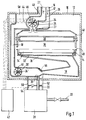
- FIG. 1 shows the heating device according to the invention for carrying out the control method according to the invention
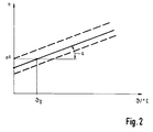
- FIG. 2 shows a compensation characteristic from which the fan speed required for a constant supply air mass flow rate can be determined as a function of the exhaust gas temperature or the supply air temperature
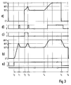
- FIG. 3 shows a functional sequence plotted over time After the heater has been switched on, it shows a) the signal for the heat request, b) the fan speed, c) the signal for the ignition, d) the condition of a pressure cell and e) the gas supply.
- the exhaust gas 27 which is produced during combustion is released into the open via the exhaust line 26.
- the supply air line 16 and the exhaust gas line 26 run coaxially to one another and are connected to the environment via an opening 40 in the housing 10.
- the temperature of the fan 24 changes conveyed exhaust gas volume flow.
- the exhaust gas temperature changes as a function of the change in the supply temperature of the heating water in the heat exchanger 38 and as a function of the device state from which the start was made (cold / warm).
- the temperature of the exhaust gas 27 is also influenced by temperature changes in the supply air 17.
- General heating of the heater, as well as the coaxial routing of the supply air line 16 to the exhaust gas line 26 and the fan 24 arranged for cooling in the supply air line 16 bring about a temperature increase in the supply air and thus also an increase in the temperature of the exhaust gas 27 during combustion.
- exhaust gas 27, that is, the fan is running there is combustion.
- the designation nominal speed means that the blower works with 100% output taking into account the necessary compensation of the speed due to the different exhaust gas temperatures.
- the fan 24 is started up first when a heat is requested via the control unit 42.
- the exhaust air volume flow conveyed by the fan 24 corresponds to a specific supply air volume flow.
- the difference in the pressures detected by the control lines 50, 52 in the channel-shaped line 18 is a measure of the delivered supply air volume flow.
- the contacts of the pressure cell 54 attached between the control lines 50, 52 close at a point in time t1.
- the speed of the fan 24 which in this case corresponds to 80% of the nominal speed of the fan 24 and the temperature by the Sensor 46 detected exhaust air 27 stored in the control unit 42.
- the speed of the fan 24 is detected with the aid of a sensor 44 attached to the fan 24.
- the sensor 46 is arranged on the inside of the housing 25 of the fan 24. He is thus directly exposed to the temperature of the exhaust gas 27 being conveyed.
- PTC resistors, thermocouples or NTC resistors can be used as temperature sensors. The latter have the advantage that they have a relatively large linear characteristic range.
- the sensor 46 consists of two NTC resistors with different resistance values, preferably 10 k ⁇ for a temperature range from 0 ° to 90 ° C and 100 k ⁇ for a temperature range from 90 ° C to 200 ° C.
- the fan 24 ' is arranged in the supply air duct 18, the combustion chamber 36 and the exhaust gas-carrying parts must be designed to be tight.
- the control procedure is just as little on Restricted gas heaters, but can in principle also be used for heaters with other energy sources, such as oil.
Landscapes
- Engineering & Computer Science (AREA)
- Chemical & Material Sciences (AREA)
- Combustion & Propulsion (AREA)
- Mechanical Engineering (AREA)
- General Engineering & Computer Science (AREA)
- Regulation And Control Of Combustion (AREA)
Abstract
Description
Die Erfindung geht aus von einem Verfahren und einer Vorrichtung zur Regelung eines Heizgerätes nach der Gattung der Ansprüche 1 und 8.The invention relates to a method and a device for regulating a heater according to the type of
Durch die DE 31 25 513 A1 ist ein Verfahren und eine Vorrichtung zum Betreiben einer Vergasungsbrenner-Heizkesselanlage bekannt geworden, bei dem aus der gemessenen Außenlufttemperatur und der Kesselvorlauftemperatur die erforderliche Brennerleistung ermittelt wird und dann der Luftmassenstrom und der Heizölmassenstrom als Funktion der geforderten Brennerleistung im stöchiometrischen Verhältnis dem Brenner zugeführt werden. Abweichungen des Luftmassenstroms vom Sollwert werden mittels eines Luftmassenstromfühlers im Gesamtluftstrom erfaßt und als Signal dem Regelgerät zugeführt. Das Regelgerät veranlaßt eine entsprechende Drehzahlregulierung des die Verbrennungsluft zuführenden Gebläses.DE 31 25 513 A1 discloses a method and a device for operating a gasification burner heating boiler system in which the required burner output is determined from the measured outside air temperature and the boiler flow temperature and then the air mass flow and the heating oil mass flow as a function of the required burner output in stoichiometric Ratio are fed to the burner. Deviations in the air mass flow from the setpoint are detected by an air mass flow sensor in the total air flow and sent to the control device as a signal. The control device initiates a corresponding speed regulation of the fan supplying the combustion air.
Das erfindungsgemäße Regelverfahren mit den Merkmalen des Anspruchs 1 hat den Vorteil, daß der der Wärmeanforderung entsprechend dem Brenner zugeführte Luftmassenstrom trotz Änderung seines Volumens aufgrund von Änderungen der Zulufttemperatur oder trotz Änderung des Abgasvolumens aufgrund von Änderungen der Abgastemperatur auf einem vorgegebenen Wert gehalten wird. Damit tritt ein Leistungsabfall aufgrund dieser Temperaturänderungen nicht ein.The control method according to the invention with the features of
Durch die in den Unteransprüchen aufgeführten Maßnahmen sind vorteilhafte Weiterbildungen für das Regelverfahren möglich.Advantageous further developments for the control method are possible through the measures listed in the subclaims.
Die Zuordnung der Gebläsedrehzahl in Abhängigkeit von der Abgas- oder Zulufttemperatur wird durch eine in einem Steuergerät abgelegte Kompensationskennlinie bestimmt. Diese setzt sich zusammen aus Erfahrungswerten, die ergänzt werden durch vom Heizgerät vor dem Beginn des ersten Heizvorgangs selbst ermittelte Parameter, wie z.B. den Strömungsinnenwiderstand. Damit wird erreicht, daß während des Betriebs jeder Abgas- oder Zulufttemperatur eine entsprechend der Kompensation notwendige Gebläsedrehzahl zugeordnet wird.The allocation of the fan speed depending on the exhaust gas or supply air temperature is determined by a compensation characteristic stored in a control unit. This is composed of empirical values that are supplemented by parameters determined by the heater itself before the start of the first heating process, such as the internal flow resistance. This ensures that a fan speed required in accordance with the compensation is assigned to each exhaust gas or supply air temperature during operation.
Die Drehzahl zur Bestimmung der Kompensationskennlinie, die einem vorbestimmten Zuluftvolumenstrom entspricht, wird in Abhängigkeit von der Bauform des Heizgeräts und in Abhängigkeit von der Temperatur der Abluft oder der Zuluft ermittelt. Das hat u.a. den Vorteil, daß das Regelverfahren auch bei Heizgeräten mit unterschiedlichen Strömungsinnenwiderständen universell eingesetzt werden kann.The speed for determining the compensation characteristic, which corresponds to a predetermined supply air volume flow, is determined as a function of the design of the heater and as a function of the temperature of the exhaust air or the supply air. Among other things, the advantage that the control method can also be used universally in heaters with different internal flow resistances.
Da sich die zur Bestimmung der Kompensationskennlinie erforderlichen Parameter, wie z.B. der Strömungsinnenwiderstand des Heizgeräts, ändern können, ist es vorteilhaft, die Kompensationskennlinie in regelmäßigen Abständen zu überprüfen und gegebenenfalls zu korrigieren. Damit wird erreicht, daß das erfindungsgemäße Regelverfahren an diese möglichen Änderungen angepaßt wird.Since the parameters required for determining the compensation characteristic, such as the internal flow resistance of the heater, it is advantageous to check the compensation characteristic at regular intervals and correct it if necessary. This ensures that the control method according to the invention is adapted to these possible changes.
Das erfindungsgemäße Heizgerät hat den Vorteil, daß trotz unterschiedlicher Temperaturen des durch das Gebläse geförderten Volumenstroms die Gebläsedrehzahl so eingestellt ist, daß der Zuluftmassenstrom auf dem der Wärmeanforderung entsprechenden Wert gehalten wird.The heater according to the invention has the advantage that, despite different temperatures of the volume flow conveyed by the fan, the fan speed is set so that the supply air mass flow is kept at the value corresponding to the heat requirement.
Da ein näherungsweise linearer Zusammenhang zwischen der Zuluft- oder der Abgastemperatur und der Masse des zum Brenner gelangenden Luftstromes besteht, ist es vorteilhaft, als Temperaturmeßfühler Widerstände mit linear veränderlichem Temperaturkoeffizienten einzusetzen. Handelsübliche NTC-Widerstände haben den Vorteil, daß sie einen relativ großen linearen Kennlinienbereich besitzen. Sollte der zu regelnde Temperaturbereich dennoch größer sein, so ist es zweckmäßig, einen Kombinationswiderstand aus zwei ggf. unterschiedlichen Widerständen mit negativen Temperaturkoeffizienten einzusetzen, deren lineare Kennlinienbereiche zusammen den gesamten zu regelnden Temperaturbereich erfassen.Since there is an approximately linear relationship between the supply air or the exhaust gas temperature and the mass of the air stream reaching the burner, it is advantageous to use resistors with a linearly variable temperature coefficient as the temperature sensor. Commercial NTC resistors have the advantage that they have a relatively large linear characteristic range. If the temperature range to be controlled is nevertheless larger, it is expedient to use a combination resistor composed of two possibly different resistors with negative temperature coefficients, the linear characteristic ranges of which together cover the entire temperature range to be controlled.
Es ist besonders vorteilhaft, das Gebläse abgasseitig anzuordnen, da in diesem Fall auf Grund des in der Brennkammer herrschenden Unterdrucks keine Abdichtungen im Brennkammerbereich notwendig sind. Dadurch kann auch bei einer offen ausgebildeten Brennkammer kein Abgas aus der Brennkammer entweichen. Ist das Gebläse abgasseitig angeordnet, so ist in diesem Fall der Zuluftmassenstrom vom geförderten Abgasmassenstrom abhängig. Steigt die Temperatur des Abgases, so steigt das Abgasvolumen an. Die Dichte des Abgases nimmt ab, damit wird ein kleinerer Abgasmassenstrom und somit auch ein kleinerer Zuluftmassenstrom durch das abgasseitig angeordnete Gebläse gefördert. Insbesondere in diesem Fall findet das erfindungsgemäße Regelverfahren seine Anwendung, indem in Abhängigkeit von der erfaßten Abgastemperatur die Gebläsedrehzahl so geregelt wird, daß der Zuluftmassenstrom auf dem der Wärmeanforderung entsprechenden Wert gehalten wird.It is particularly advantageous to arrange the fan on the exhaust gas side, since in this case no seals in the combustion chamber area are necessary due to the negative pressure prevailing in the combustion chamber. As a result, even with an open combustion chamber, no exhaust gas can escape from the combustion chamber. If the blower is arranged on the exhaust gas side, the supply air mass flow is dependent on the exhaust gas mass flow being conveyed in this case. If the temperature of the exhaust gas rises, the exhaust gas volume increases. The density of the exhaust gas decreases a smaller exhaust gas mass flow and thus also a smaller supply air mass flow is thus conveyed through the fan arranged on the exhaust gas side. In this case in particular, the control method according to the invention is used in that the fan speed is controlled as a function of the detected exhaust gas temperature so that the supply air mass flow is kept at the value corresponding to the heat requirement.
Ein Ausführungsbeispiel der Erfindung ist in der Zeichnung dargestellt und in der nachfolgenden Beschreibung näher erläutert. Es zeigen Fig. 1 das erfindungsgemäße Heizgerät zur Durchführung des erfindungsgemäßen Regelverfahrens, Fig. 2 eine Kompensationskennlinie, aus der in Abhängigkeit der Abgastemperatur oder der Zulufttemperatur die für eine Zuluft-Massenstromkonstanz notwendige Gebläsedrehzahl ermittelt werden kann und Fig. 3 einen Funktionsablauf aufgetragen über der Zeit, nachdem das Heizgerät eingeschaltet wurde, dabei zeigt a) das Signal für die Wärmeanforderung, b) die Gebläsedrehzahl, c) das Signal für die Zündung, d) den Zustand einer Druckdose und e) die Gaszufuhr.An embodiment of the invention is shown in the drawing and explained in more detail in the following description. 1 shows the heating device according to the invention for carrying out the control method according to the invention, FIG. 2 shows a compensation characteristic from which the fan speed required for a constant supply air mass flow rate can be determined as a function of the exhaust gas temperature or the supply air temperature, and FIG. 3 shows a functional sequence plotted over time After the heater has been switched on, it shows a) the signal for the heat request, b) the fan speed, c) the signal for the ignition, d) the condition of a pressure cell and e) the gas supply.
Das Heizgerät nach Fig. 1 weist eine von einem Gehäuse 10 gasdicht umgebene Unterdruckkammer 12 auf, in der ein mit einem Luft-Brenngasgemisch beaufschlagter Brenner 14 angeordnet ist. Durch eine Zuluftleitung 16 wird die Zuluft 17 durch ein in einer Abgasleitung 26 angeordnetes Gebläse 24 in einen Zuluftkanal 18 gefördert, in welchen an einer Stelle 20 eine über eine Gasregeleinrichtung 28 führende Gasleitung 22 einmündet, wobei im weiteren Verlauf des Zuluftkanals 18 eine Vermischung von Brenngas und Verbrennungsluft stattfindet. Die Gasregeleinrichtung 28 steht neben der Gasleitung 22 auch über Steuerleitungen 50,52 mit dem in diesem Bereich als Volumenstrommeßstelle ausgebildeten Zuluftkanal 18 in Verbindung. Die Messung des Zuluftvolumenstroms erfolgt dabei durch die Erfassung des Differenzdrucks im Bereich einer Querschnittsveränderung des Zuluftkanals 18. Dadurch wird erreicht, daß in Abhängigkeit vom Zuluftvolumenstrom durch die Gasregeleinrichtung 28 eine für eine näherungsweise stöchiometrische Verbrennung erforderliche Gasmenge zugeführt wird. Darüberhinaus ist zwischen den beiden Steuerleitungen 50,52 ein Strömungsschalter in Form einer Druckdose 54 angeschlossen. Der Zuluftkanal 18 führt in eine Verteilerkammer 30 des Brenners 14, aus welcher das Brenngas-Luftgemisch durch ein Lochblech 32 gleichmäßig verteilt in eine Brennzone 34 des Brenners 14 gelangt. Die Verbrennung erfolgt in einer Brennkammer 36, über der ein Wärmeübertrager 38 für das zu erhitzende Wasser angeordnet ist. In Strömungsrichtung hinter dem Wärmeübertrager 38 gelangt das bei der Verbrennung entstehende Abgas 27 über die Abgasleitung 26 ins Freie. Die Zuluftleitung 16 und die Abgasleitung 26 verlaufen koaxial zueinander und stehen über eine Öffnung 40 im Gehäuse 10 mit der Umgebung in Verbindung.1 has a
Es ist bekannt, daß die Leistung eines Heizgerätes während der Heizphase entsprechend der Wärmeanforderung geregelt wird. Bei Heizgeräten mit einer gebläseunterstützten Luftzufuhr erfolgt die Leistungsregelung mit einem vorzugsweise stetig regelbaren Gebläse 24 dadurch, daß ein entsprechend der Wärmeanforderung für eine näherungsweise stöchiometrische Verbrennung notwendiger Luftmassenstrom dem Verbrennungsvorgang zur Verfügung gestellt wird.It is known that the output of a heater is regulated during the heating phase in accordance with the heat requirement. In heaters with a fan-assisted air supply, the power is regulated with a
Während des Betriebs des Heizgeräts, insbesondere in der Anfangsphase ändert sich die Temperatur des durch das Gebläse 24 geförderten Abgasvolumenstroms. Die Abgastemperatur ändert sich in Abhängigkeit von der Änderung der Vorlauftemperatur des Heizwassers im Wärmeübertrager 38 und in Abhängigkeit vom Gerätezustand, aus dem gestartet wurde (kalt/warm). Darüberhinaus wird die Temperatur des Abgases 27 auch durch Temperaturänderungen der Zuluft 17 beeinflußt. Eine allgemeine Erwärmung des Heizgeräts, sowie die koaxiale Führung der Zuluftleitung 16 zur Abgasleitung 26 und das zur Kühlung in der Zuluftleitung 16 angeordnete Gebläse 24 bewirken eine Temperaturerhöhung der Zuluft und damit auch eine Erhöhung der Temperatur des Abgases 27 während der Verbrennung. Steigt die Temperatur in der Brennkammer 36 und die Temperatur des Abgases 27, so steigt auch das Abgasvolumen an, während sich der Druck in der Brennkammer 36 nicht wesentlich erhöht. Durch das gestiegene Abgasvolumen nimmt die Dichte des Abgases 27 ab, so daß ein kleinerer Abgasmassenstrom durch das Gebläse 24 gefördert wird. Dieser reduzierte Abgasmassenstrom bewirkt einen kleineren Zuluftmassenstrom und damit einen Abfall der eingestellten Heizleistung, der sich dann beispielsweise in einer unerwünschten Abnahme der eingestellten Brauchwassertemperatur äußert.During the operation of the heater, particularly in the initial phase, the temperature of the
Erfindungsgemäß wird die Abgastemperatur durch einen im Bereich des Gebläses 24 angeordneten und von der Temperatur des durch das Gebläse 24 geförderten Abgasvolumenstroms beaufschlagten Meßfühlers 46 erfaßt, in einem Steuergerät 42 ausgewertet und die Gebläsedrehzahl durch das Steuergerät 42 so geregelt, daß der Zuluftmassenstrom auf dem der Wärmeanforderung entsprechenden Wert gehalten wird.According to the invention, the exhaust gas temperature is detected by a
Die von der Temperatur des Abgases 27 abhängige Gebläsedrehzahl wird in vorteilhafter Weise durch eine im Steuergerät 42 abgelegte Kompensationskennlinie bestimmt.The fan speed, which is dependent on the temperature of the
Das erfindungsgemäße Regelverfahren wird im folgenden anhand von Fig. 3 näher erläutert. Im folgenden wird zwischen Abluft 27, das heißt, das Gebläse 24 läuft, eine Verbrennung findet nicht statt, und Abgas 27, das heißt, das Gebläse läuft, eine Verbrennung findet statt, unterschieden. Die Bezeichnung Nenndrehzahl bedeutet, daß das Gebläse mit 100%- Leistung unter Berücksichtigung der notwendigen Kompensation der Drehzahl aufgrund der unterschiedlichen Abgastemperaturen arbeitet.The control method according to the invention is explained in more detail below with reference to FIG. 3. In the following, a distinction is made between
Wird das Heizgerät zum Zeitpunkt t0 eingeschaltet, so wird bei einer Wärmeanforderung über das Steuergerät 42 als erstes das Gebläse 24 in Betrieb genommen. Der durch das Gebläse 24 geförderte Abluftvolumenstrom entspricht dabei einem bestimmten Zuluftvolumenstrom. Die Differenz der von den Steuerleitungen 50, 52 erfaßten Drücke in der kanalförmigen Leitung 18 sind ein Maß für den geförderten Zuluftvolumenstrom. Bei einem vorbestimmten Differenzdruck schließen zu einem Zeitpunkt t1 die Kontakte der zwischen den Steuerleitungen 50,52 angebrachten Druckdose 54. Bei diesem Zuluftvolumenstrom wird die Drehzahl des Gebläses 24, die in diesem Fall 80% der Nenndrehzahl des Gebläses 24 entspricht und die Temperatur der durch den Meßfühler 46 erfaßten Abluft 27 im Steuergerät 42 gespeichert. Dabei wird die Drehzahl des Gebläses 24 mit Hilfe eines am Gebläse 24 angebrachten Sensors 44 erfaßt. Als Sensor 44 kann beispielsweise ein handelsüblicher Hallsensor eingesetzt werden. Die so erfaßte Drehzahl, aus der die Nenndrehzahl berechnet wird, kann in Abhängigkeit vom Strömungswiderstand im Heizgerät variieren. Der Strömungswiderstand ist dabei u.a. von der Länge und der sowohl stromauf als auch stromab des Gebläses 24 angeordneten Zu- und Abluft führenden Teile abhängig. So wird z.B. mit einer längeren Abgasleitung 26 ein größerer Strömungswiderstand im Heizgerät erzeugt; damit wird eine höhere Gebläsedrehzahl notwendig, um den gleichen Zuluftvolumenstrom zu fördern.If the heater is switched on at time t0, the
Um bei der Bestimmung der Nenndrehzahl auch die Temperatur der Zuluft 27 zu berücksichtigen, sind im Bereich der als Volumenstrommeßstelle ausgebildeten kanalförmigen Leitung 18 Mittel 56 eingesetzt, die den Differenzdruck in Abhängigkeit der Zulufttemperatur beeinflussen. Steigt die Temperatur der Zuluft 17, so wird mit Hilfe der eingesetzten Mittel 56, z.B. mit einem Bimetallelement, der durch die Druckdose 54 erfaßte Differenzdruck erst bei einer höheren Gebläsedrehzahl, d.h. bei einer höheren Nenndrehzahl erreicht. Diese von der Zulufttemperatur abhängige Steuerung des Differenzdrucks, die vor allem die Gasregeleinrichtung 28 beeinflußt, kann für die Bestimmung der Nenndrehzahl in Abhängigkeit der Ablufttemperatur benutzt werden, da die Temperatur der Abluft 27 von der Temperatur der Zuluft 17 abhängig ist.In order to also take into account the temperature of the
In Abhängigkeit von der durch den Sensor 44 erfaßten Drehzahl und der durch den Meßfühler 46 erfaßten Ablufttemperatur wird eine Kompensationskennlinie (Fig. 2) für die Nenndrehzahlen in Abhängigkeit von den im Heizbetrieb erfaßten Abgastemperaturen bestimmt und im Steuergerät 42 abgespeichert. Die zur Bestimmung der Kompensationskennlinie erforderliche Steigung a kann experimentell oder rechnerisch ermittelt werden.Depending on the speed detected by
Experimentell läßt sich die Steigung a bezogen auf das Ausführungsbeispiel im Labor auf folgende Art und Weise ermitteln: Während des Betriebs, insbesondere in der Startphase des Heizens wird bei unterschiedlichen Abgastemperaturen die Gebläsedrehzahl bestimmt, die notwendig ist, damit die Nennbelastung beziehungsweise 100% Heizleistung erreicht wird. Die Nennbelastung ist dann erreicht, wenn durch die Gasregeleinrichtung 28 eine maximale Gaszufuhr erfolgt. Die Gaszufuhr wird, wie eingangs beschrieben, in Abhängigkeit des durch das Gebläse 24 geförderten Zuluftvolumenstroms geregelt. Bei verschiedenen durch den Meßfühler 46 erfaßten Abgastemperaturen waren unterschiedliche Gebläsedrehzahlen erforderlich, um Nennbelastung zu erreichen. Die Gebläsedrehzahlen wurden bei verschiedenen Abgastemperaturen als Meßpunkte bestimmt und damit die Steigung a ermittelt.The slope a can be determined experimentally in relation to the exemplary embodiment in the laboratory in the following way: During operation, particularly in the start-up phase of heating, the fan speed is determined at different exhaust gas temperatures, so that the nominal load or 100% heating capacity is reached . The nominal load is reached when the
Die in Fig. 2 durchgezogen dargestellte Kennlinie kann, wie bereits erwähnt, in Abhängigkeit vom Strömungswiderstand im Heizgerät variieren, was durch die gestrichelt dargestellten Kennlinien angedeutet wird.As already mentioned, the characteristic shown in solid line in FIG. 2 can vary depending on the flow resistance in the heater, which is indicated by the characteristic shown in broken lines.
Die Kompensationskennlinie (Fig. 2) wurde für die Nenndrehzahlen bestimmt, d.h. die Gebläsedrehzahlen die bei 100% Heizleistung gefordert sind. Da die Gebläsedrehzahlen vor allem während des Heizbetriebs entsprechend der Wärmeanforderung zwischen 60% und 100% regelbar sind, werden in diesem Fall die erforderlichen Kompensationsdrehzahlen durch eine entprechende Wichtung der aus der Kompensationskennlinie ermittelten Nenndrehzahlen bestimmt. Da eine im wesentlichen lineare Abhängigkeit zwischen der Höhe der Heizleistung und der Höhe der Abgastemperatur besteht, wird z.B. bei 60% geforderter Heizleistung, der aus der Kompensationskennlinie ermittelte Wert der Nenndrehzahl mit dem Faktor 0.6 multipliziert.The compensation characteristic (Fig. 2) was determined for the nominal speeds, i.e. the fan speeds that are required at 100% heating output. Since the fan speeds can be regulated between 60% and 100%, especially during heating, in accordance with the heat requirement, the required compensation speeds are determined in this case by appropriate weighting of the nominal speeds determined from the compensation characteristic. Since there is an essentially linear relationship between the amount of heating power and the amount of exhaust gas temperature, e.g. at 60% required heating output, multiply the value of the nominal speed determined from the compensation characteristic by the factor 0.6.
Die Gebläsedrehzahl wird entsprechend der ermittelten Kompensationskennlinie eingestellt. Die Gebläsedrehzahl wird von 80 % auf 60 % der Nenndrehzahl gesenkt. Die Kontakte der Druckdose 54 öffnen durch das Absenken der Drehzahl.The fan speed is set according to the determined compensation characteristic. The fan speed is reduced from 80% to 60% of the nominal speed. The contacts of the
Die Gebläsedrehzahl wird auf 80% der Nenndrehzahl erhöht, die Gaszufuhr geöffnet und das Brenngas-Luftgemisch gezündet. Dabei entspricht die Menge der Gaszufuhr 80% der maximalen Heizleistung.The fan speed is increased to 80% of the nominal speed, the gas supply is opened and the fuel gas / air mixture is ignited. The amount of gas supply corresponds to 80% of the maximum heating output.
Sind zum Zeitpunkt t3 80% der Nenndrehzahl erreicht, schaltet, vorausgesetzt die Zuluft- und Abgaswege sind frei, die Druckdose 54. Dann arbeitet das Heizgerät bis zum Zeitpunkt t4 unabhängig von der Höhe der Wärmeanforderung mit 60% der Heizleistung.If 80% of the nominal speed is reached at time t3, the
Da in Fig. 3 aus Gründen der Übersichtlichkeit nur zwischen der Wärmeanforderung Ja/Nein unterschieden wird, wird in Fig. 3 davon ausgegangen, daß 100% der Heizleistung gefordert sind. Die durch die Kompensationskennlinie eingestellte Drehzahl entspricht dann der Nenndrehzahl, dabei wird die für eine näherungsweise stöchiometrische Verbrennung notwendige Gasmenge dem Brenner 14 zugeführt.Since, for reasons of clarity, a distinction is only made between the yes / no heat requirement in FIG. 3, it is assumed in FIG. 3 that 100% of the heating power is required. The speed set by the compensation characteristic then corresponds to the nominal speed, and the amount of gas required for an approximately stoichiometric combustion is fed to the
Ist z.B. die Brauchwasserentnahme beendet oder der Sollwert der geforderten Raumtemperatur erreicht, wird die Gaszufuhr gestoppt. Die Gebläsedrehzahl wird vom zuletzt eingestellten Wert bis zum Zeitpunkt t6 auf null heruntergefahren.Is e.g. the hot water supply is stopped or the hot water supply stops or the setpoint reaches the required room temperature. The blower fan speed is reduced from the last set value to zero at time t6.
Ein Abgleich, d.h. eine Überprüfung und gegebenenfalls eine Korrektur der Kompensationskennlinie findet in regelmäßigen Abständen, vorzugsweise alle 24 h statt, da sich während des Betriebs des Heizgeräts der Gesamtströmungswiderstand ändern kann. Dieser Abgleich kann auch während oder im Anschluß an einen Heizvorgang erfolgen, wobei die Nenndrehzahl und die Abgas- bzw. Ablufttemperatur zur Bestimmung der Kompensationskennlinie in das Steuergerät neu eingelesen werden.A comparison, ie a check and, if necessary, a correction of the compensation characteristic curve takes place at regular intervals Intervals, preferably every 24 h, since the total flow resistance can change during operation of the heater. This adjustment can also take place during or after a heating process, the nominal speed and the exhaust gas or exhaust air temperature being read into the control unit to determine the compensation characteristic.
Der Meßfühler 46 ist an der Innenseite des Gehäuses 25 des Gebläses 24 angeordnet. Damit wird er direkt der Temperatur des geförderten Abgases 27 ausgesetzt. Als Temperaturmeßfühler können beispielsweise PTC-Widerstände, Thermoelemente oder aber NTC-Widerstände eingesetzt werden. Letztere haben den Vorteil, daß sie einen relativ großen linearen Kennlinienbereich aufweisen. Im Ausführungsbeispiel besteht der Meßfühler 46 aus zwei NTC- Widerständen mit unterschiedlichen Widerstandswerten, vorzugsweise 10 kΩ für einen Temperaturbereich von 0° bis 90 °C und 100 kΩ für einen Temperaturbereich von 90 °C bis 200 °C.The
Das Gebläse 24 ist im Ausführungsbeispiel abgasseitig angeordnet, so daß beim Arbeiten des Gebläses 24 in der Brennkammer 36 ein Unterdruck erzeugt wird. Die Brennkammer 36 steht durch Öffnungen 48 mit der durch das Gehäuse 10 gebildeten Kammer 12, in der auf Grund der Öffnungen 48 auch ein Unterdruck erzeugt wird, in Verbindung. Durch den Zuluftkanal 18 ist es im Zusammenwirken mit dem gasdicht abschließenden Gehäuse 10 möglich, die Brennkammer 36 auch für raumluftunabhängige, sogenannte Außenwand-Heizgeräte zu verwenden. Vorteilhaft u.a. ist, daß somit keine Abdichtungen im Brennkammerbereich erforderlich sind. Zur Kühlung des Gebläses 24 ist es im kastenförmig erweiterten Bereich 58 des Zuluftkanals 18 angeordnet. Die Zuluftleitung 16 ist außerhalb des Heizgeräts konzentrisch zur Abgasleitung 26 angeordnet, dadurch wird die Zuluft 17 in vorteilhafter Weise vorgewärmt.In the exemplary embodiment, the
Das zur Durchführung des erfindungsgemäßen Regelverfahrens in Fig. 1 dargestellte Heizgerät ist, wie bereits erwähnt, ein Außenwand-Heizgerät, d.h. die für die Verbrennung notwendige Zuluft 17 wird von der Außenumgebung durch die Zuluftleitung 16 bezogen. Das Regelverfahren ist aber auch bei raumluftabhängigen Heizgeräten, d.h. die Zuluft 17 wird direkt aus dem Aufstellraum des Heizgeräts bezogen, einsetzbar.The heater shown in Fig. 1 for performing the control method according to the invention is, as already mentioned, an outer wall heater, i.e. the
Das erfindungsgemäße Regelverfahren kann darüberhinaus auch dann Anwendung finden, wenn das Gebläse 24 nicht wie im Ausführungsbeispiel beschrieben, im Abgasweg, sondern im Zuluftkanal angeordnet ist. Der vom Gebläse 24' direkt geförderte Zuluftmassenstrom ist dann von der Temperatur der Zuluft 17 abhängig. Steigt die Zulufttemperatur, so sinkt die Dichte der Zuluft 17 und der Zuluftmassenstrom nimmt ab. Auch hier ergibt sich die Notwendigkeit, daß der entsprechend der Wärmeanforderung notwendige Zuluftmassenstrom in Abhängigkeit der Zulufttemperatur konstant gehalten wird. Temperaturänderungen der Zuluft 17 sind, vor allem in der Anfangsphase des Heizens, bedingt durch die allgemeine Erwärmung des Heizgeräts, sowie durch die koaxiale Führung der Zuluftleitung 16 zur Abgasleitung 26 und durch die saison/tages- und nachtbedingten unterschiedlichen Außenlufttemperaturen. Das erfindungsgemäße Regelverfahren arbeitet auf dieselbe Art und Weise wie bei dem abgasseitig angeordneten Gebläse 24, nur mit dem Unterschied, daß mit einem an der Innenseite des Gehäuses 25' des Gebläses 24' angebrachten Meßfühlers 46' die Temperatur der Zuluft 17 vor und während des Heizvorgangs bestimmt und die Gebläsedrehzahl entsprechend einer Kompensationskennlinie nach Fig. 2 in Abhängigkeit der Zulufttemperatur eingestellt wird.The control method according to the invention can also be used if the
Wenn das Gebläse 24' im Zuluftkanal 18 angeordnet ist, so müssen die Brennkammer 36 sowie die abgasführenden Teile dicht ausgebildet sein. Das Regelverfahren ist ebensowenig auf Gasheizgeräte eingeschränkt, sondern prinzipiell auch für Heizgeräte mit anderen Energieträgern, wie zum Beispiel Öl, einsetzbar.If the fan 24 'is arranged in the
Claims (13)
daß vom Meßfühler (46,46') ein der Temperatur (17,27) entsprechendes Signal dem Steuergerät (42) zugeführt wird, daß das Steuergerät in Abhängigkeit von dem Signal einen Sollwert für die Gebläsedrehzahl ermittelt, und daß die Gebläsedrehzahl auf Grund des Sollwerts so eingestellt wird, daß der Zuluftmassenstrom auf dem der Wärmeanforderung entsprechenden Wert gehalten wird.Method for controlling a heater, preferably premixing air and fuel in a duct-shaped line, with a fuel control device and with a blower, which can be controlled by a control device as a function of the heat requirement, characterized in that at least one sensor (46, 46 ') measures the temperature of the Exhaust gas (27) or the supply air (17) detected,
that a signal corresponding to the temperature (17.27) is fed to the control unit (42) by the sensor (46, 46 '), that the control unit determines a setpoint for the fan speed as a function of the signal, and that the fan speed is based on the setpoint is set so that the supply air mass flow is kept at the value corresponding to the heat requirement.
Applications Claiming Priority (2)
| Application Number | Priority Date | Filing Date | Title |
|---|---|---|---|
| DE19510425A DE19510425C2 (en) | 1995-03-24 | 1995-03-24 | Method and device for controlling a heater |
| DE19510425 | 1995-03-24 |
Publications (2)
| Publication Number | Publication Date |
|---|---|
| EP0733859A2 true EP0733859A2 (en) | 1996-09-25 |
| EP0733859A3 EP0733859A3 (en) | 1996-12-11 |
Family
ID=7757392
Family Applications (1)
| Application Number | Title | Priority Date | Filing Date |
|---|---|---|---|
| EP96103437A Ceased EP0733859A3 (en) | 1995-03-24 | 1996-03-06 | Method and device for controlling a heating apparatus |
Country Status (2)
| Country | Link |
|---|---|
| EP (1) | EP0733859A3 (en) |
| DE (1) | DE19510425C2 (en) |
Cited By (9)
| Publication number | Priority date | Publication date | Assignee | Title |
|---|---|---|---|---|
| EP0855556A1 (en) * | 1997-01-23 | 1998-07-29 | Truma Gerätetechnik GmbH & Co. | Device and method for controlling the rotational speed of a motor |
| EP1333227A3 (en) * | 2002-01-31 | 2004-07-07 | Robert Bosch Gmbh | Method to adapt a heating device including a burner to its dedicated air-/exhaust system |
| EP1450102A1 (en) * | 2003-02-20 | 2004-08-25 | Robert Bosch Gmbh | Heating apparatus and corresponding operation method |
| EP1475580A1 (en) * | 2003-05-07 | 2004-11-10 | Robert Bosch Gmbh | Device and process for adapting the fan output of a heating device or ventilating device to the geometry of the exhaust or air system |
| EP1260766A3 (en) * | 2001-05-21 | 2004-12-08 | Vaillant GmbH | Method for adapting a fired heater to the air/flue gas stack |
| EP2455660A3 (en) * | 2010-11-18 | 2016-08-17 | Reznor Manufacturing Company, LLC | Premix air heater |
| EP3438528A4 (en) * | 2016-03-30 | 2020-02-26 | Kazuo Miyatani | SOLID FUEL COMBUSTION DEVICE, SOLID FUEL COMBUSTION METHOD, GAS HEATING DEVICE, LIQUID HEATING DEVICE, ENERGY GENERATION SYSTEM, AND COOLING SYSTEM |
| EP4033147A3 (en) * | 2021-01-25 | 2022-08-03 | Vaillant GmbH | Assembly and method for operating a heating device |
| CN119707249A (en) * | 2024-12-20 | 2025-03-28 | 彩虹(合肥)液晶玻璃有限公司 | A production management and control system for substrate glass |
Families Citing this family (2)
| Publication number | Priority date | Publication date | Assignee | Title |
|---|---|---|---|---|
| DE102010054807B4 (en) * | 2010-12-16 | 2015-07-02 | Honeywell Technologies Sarl | Method for operating a gas burner device |
| DE102021206320A1 (en) * | 2021-06-21 | 2022-12-22 | Robert Bosch Gesellschaft mit beschränkter Haftung | Method for determining and/or optimizing a heat output of a heater and heater and control device |
Family Cites Families (10)
| Publication number | Priority date | Publication date | Assignee | Title |
|---|---|---|---|---|
| DE3125513A1 (en) * | 1981-06-29 | 1983-01-13 | Siemens AG, 1000 Berlin und 8000 München | Method of operating a gasification burner/heating boiler installation |
| JPS63318417A (en) * | 1987-06-19 | 1988-12-27 | Matsushita Electric Ind Co Ltd | Controller for forced air feeding and discharging type heater |
| JPH01212817A (en) * | 1988-02-19 | 1989-08-25 | Toto Ltd | Forced exhaust type gas combustion device |
| DE3812697A1 (en) * | 1988-04-16 | 1989-12-28 | Programmelectronic Eng Ag | METHOD FOR REDUCING THE INTERFERENCE EFFECT IN FAN BURNER PLANTS AND FAN BURNER PLANT |
| JPH02192512A (en) * | 1989-01-17 | 1990-07-30 | Noritz Corp | Forced feed and discharge type combustion device |
| DE4109841C2 (en) * | 1991-03-26 | 1994-06-09 | Bosch Gmbh Robert | Control device for gas burners with a fan for supplying combustion air |
| NL9200825A (en) * | 1992-05-08 | 1993-12-01 | Fasto Nefit Bv | Fan controller |
| AT406512B (en) * | 1992-10-12 | 2000-06-26 | Vaillant Gmbh | METHOD FOR MAINTAINING THE MAXIMUM AND / OR MINIMUM PERFORMANCE OF A WATER HEATER HAVING A GAS BURNER |
| DE9310451U1 (en) * | 1993-03-05 | 1994-06-30 | Landis & Gyr Business Support Ag, Zug | Control device for automatic gas firing systems for heating systems |
| EP0615095B1 (en) * | 1993-03-11 | 1997-05-07 | Landis & Gyr Technology Innovation AG | Burner controller |
-
1995
- 1995-03-24 DE DE19510425A patent/DE19510425C2/en not_active Expired - Fee Related
-
1996
- 1996-03-06 EP EP96103437A patent/EP0733859A3/en not_active Ceased
Cited By (10)
| Publication number | Priority date | Publication date | Assignee | Title |
|---|---|---|---|---|
| EP0855556A1 (en) * | 1997-01-23 | 1998-07-29 | Truma Gerätetechnik GmbH & Co. | Device and method for controlling the rotational speed of a motor |
| EP1260766A3 (en) * | 2001-05-21 | 2004-12-08 | Vaillant GmbH | Method for adapting a fired heater to the air/flue gas stack |
| EP1333227A3 (en) * | 2002-01-31 | 2004-07-07 | Robert Bosch Gmbh | Method to adapt a heating device including a burner to its dedicated air-/exhaust system |
| EP1450102A1 (en) * | 2003-02-20 | 2004-08-25 | Robert Bosch Gmbh | Heating apparatus and corresponding operation method |
| EP1475580A1 (en) * | 2003-05-07 | 2004-11-10 | Robert Bosch Gmbh | Device and process for adapting the fan output of a heating device or ventilating device to the geometry of the exhaust or air system |
| EP2455660A3 (en) * | 2010-11-18 | 2016-08-17 | Reznor Manufacturing Company, LLC | Premix air heater |
| EP3438528A4 (en) * | 2016-03-30 | 2020-02-26 | Kazuo Miyatani | SOLID FUEL COMBUSTION DEVICE, SOLID FUEL COMBUSTION METHOD, GAS HEATING DEVICE, LIQUID HEATING DEVICE, ENERGY GENERATION SYSTEM, AND COOLING SYSTEM |
| EP4033147A3 (en) * | 2021-01-25 | 2022-08-03 | Vaillant GmbH | Assembly and method for operating a heating device |
| CN119707249A (en) * | 2024-12-20 | 2025-03-28 | 彩虹(合肥)液晶玻璃有限公司 | A production management and control system for substrate glass |
| CN119707249B (en) * | 2024-12-20 | 2026-01-06 | 彩虹(合肥)液晶玻璃有限公司 | A substrate glass production management and control system |
Also Published As
| Publication number | Publication date |
|---|---|
| DE19510425C2 (en) | 1999-05-27 |
| DE19510425A1 (en) | 1996-09-26 |
| EP0733859A3 (en) | 1996-12-11 |
Similar Documents
| Publication | Publication Date | Title |
|---|---|---|
| DE102004055716C5 (en) | Method for controlling a firing device and firing device (electronic composite I) | |
| DE3888327T2 (en) | Fuel burner device and a control method. | |
| DE3422866C3 (en) | METHOD AND DEVICE FOR CONTROLLING A HOT WIRE AIR METER FOR INTERNAL COMBUSTION ENGINES | |
| DE19510425C2 (en) | Method and device for controlling a heater | |
| DE4317981A1 (en) | Gas-air ratio control device for a temperature control loop for gas appliances | |
| EP1761728A1 (en) | Method for adjusting the excess air coefficient on a firing apparatus, and firing apparatus | |
| EP3593047B1 (en) | Method for identifying the type of fuel gas during the starting operation of a fuel-gas-operated heating device and fuel-gas-operated heating device | |
| EP1236957B1 (en) | Process and device for adapting a burner-activated heating apparatus to an air-flue gas system | |
| EP0505714B1 (en) | Control device for a gas burner with a fan for supplying combustion air | |
| AT408033B (en) | METHOD FOR ADAPTING A BURNER-HEATED HEATER | |
| DE102004055715C5 (en) | Method for setting operating parameters on a firing device and firing device | |
| DE10140388C2 (en) | Heater for mobile applications | |
| EP0239842B1 (en) | Method for regulating interior temperature, especially that of a motor vehicle | |
| DE4334625A1 (en) | Process for keeping the output of a water heater constant | |
| DE69113959T2 (en) | Drying device and its control device for rotary printing press. | |
| EP1333227B1 (en) | Method to adapt a heating device including a burner to its dedicated air-/exhaust system | |
| DE102021121093A1 (en) | Method for operating a heater, computer program, storage medium, regulation and control device, heater and use of a signal | |
| DE10340194B4 (en) | Method for adjusting the fan speed of a fan-assisted heater | |
| DE102004063992B4 (en) | Regulating and controlling process for firing apparatus involves using characteristic curve showing value range for setpoint temperature in accordance with two parameters | |
| DE60027582T2 (en) | Control system for a combustion system | |
| DE202004017851U1 (en) | Firing equipment for gas burners has means for determining value dependent on measured temperature and means for regulating generated temperature using characteristic line representing value range corresponding to ideal temperature | |
| DE202004017850U1 (en) | Firing equipment as gas burner has means to set a desired target parameter value after determining the parameter value corresponding to the temperature maximum for optimum air-gas ratio | |
| DE102004030299A1 (en) | Firing equipment for gas burners has means for determining value dependent on measured temperature and means for regulating generated temperature using characteristic line representing value range corresponding to ideal temperature | |
| DE102004030300A1 (en) | Firing equipment as gas burner has means to set a desired target parameter value after determining the parameter value corresponding to the temperature maximum for optimum air-gas ratio | |
| EP1260766B1 (en) | Method for adapting a fired heater to the air/flue gas stack |
Legal Events
| Date | Code | Title | Description |
|---|---|---|---|
| PUAI | Public reference made under article 153(3) epc to a published international application that has entered the european phase |
Free format text: ORIGINAL CODE: 0009012 |
|
| AK | Designated contracting states |
Kind code of ref document: A2 Designated state(s): DE FR GB IT NL |
|
| PUAL | Search report despatched |
Free format text: ORIGINAL CODE: 0009013 |
|
| AK | Designated contracting states |
Kind code of ref document: A3 Designated state(s): DE FR GB IT NL |
|
| 17P | Request for examination filed |
Effective date: 19970611 |
|
| 17Q | First examination report despatched |
Effective date: 19980223 |
|
| STAA | Information on the status of an ep patent application or granted ep patent |
Free format text: STATUS: THE APPLICATION HAS BEEN REFUSED |
|
| 18R | Application refused |
Effective date: 19980917 |