EP0733763B1 - Ferme-porte - Google Patents
Ferme-porte Download PDFInfo
- Publication number
- EP0733763B1 EP0733763B1 EP19960104540 EP96104540A EP0733763B1 EP 0733763 B1 EP0733763 B1 EP 0733763B1 EP 19960104540 EP19960104540 EP 19960104540 EP 96104540 A EP96104540 A EP 96104540A EP 0733763 B1 EP0733763 B1 EP 0733763B1
- Authority
- EP
- European Patent Office
- Prior art keywords
- piston
- power accumulator
- partial power
- accordance
- door
- Prior art date
- Legal status (The legal status is an assumption and is not a legal conclusion. Google has not performed a legal analysis and makes no representation as to the accuracy of the status listed.)
- Expired - Lifetime
Links
- 238000007789 sealing Methods 0.000 claims description 19
- 238000000034 method Methods 0.000 claims description 18
- 230000000694 effects Effects 0.000 claims description 9
- 230000000903 blocking effect Effects 0.000 claims description 7
- 238000013016 damping Methods 0.000 claims description 4
- 238000012544 monitoring process Methods 0.000 claims description 2
- 230000001419 dependent effect Effects 0.000 claims 3
- 238000007599 discharging Methods 0.000 claims 2
- 230000001960 triggered effect Effects 0.000 claims 2
- 238000004146 energy storage Methods 0.000 description 12
- 230000001105 regulatory effect Effects 0.000 description 5
- 230000006835 compression Effects 0.000 description 4
- 238000007906 compression Methods 0.000 description 4
- 239000012530 fluid Substances 0.000 description 4
- 229920001971 elastomer Polymers 0.000 description 3
- 239000000806 elastomer Substances 0.000 description 3
- 239000010720 hydraulic oil Substances 0.000 description 3
- 239000000463 material Substances 0.000 description 3
- 230000036962 time dependent Effects 0.000 description 2
- 230000001133 acceleration Effects 0.000 description 1
- 239000000853 adhesive Substances 0.000 description 1
- 230000001070 adhesive effect Effects 0.000 description 1
- 239000002131 composite material Substances 0.000 description 1
- 230000001276 controlling effect Effects 0.000 description 1
- 230000003111 delayed effect Effects 0.000 description 1
- 230000036316 preload Effects 0.000 description 1
- 230000002028 premature Effects 0.000 description 1
- 230000000750 progressive effect Effects 0.000 description 1
Images


Classifications
-
- E—FIXED CONSTRUCTIONS
- E05—LOCKS; KEYS; WINDOW OR DOOR FITTINGS; SAFES
- E05F—DEVICES FOR MOVING WINGS INTO OPEN OR CLOSED POSITION; CHECKS FOR WINGS; WING FITTINGS NOT OTHERWISE PROVIDED FOR, CONCERNED WITH THE FUNCTIONING OF THE WING
- E05F3/00—Closers or openers with braking devices, e.g. checks; Construction of pneumatic or liquid braking devices
- E05F3/22—Additional arrangements for closers, e.g. for holding the wing in opened or other position
- E05F3/223—Hydraulic power-locks, e.g. with electrically operated hydraulic valves
-
- E—FIXED CONSTRUCTIONS
- E05—LOCKS; KEYS; WINDOW OR DOOR FITTINGS; SAFES
- E05F—DEVICES FOR MOVING WINGS INTO OPEN OR CLOSED POSITION; CHECKS FOR WINGS; WING FITTINGS NOT OTHERWISE PROVIDED FOR, CONCERNED WITH THE FUNCTIONING OF THE WING
- E05F3/00—Closers or openers with braking devices, e.g. checks; Construction of pneumatic or liquid braking devices
- E05F3/04—Closers or openers with braking devices, e.g. checks; Construction of pneumatic or liquid braking devices with liquid piston brakes
- E05F3/10—Closers or openers with braking devices, e.g. checks; Construction of pneumatic or liquid braking devices with liquid piston brakes with a spring, other than a torsion spring, and a piston, the axes of which are the same or lie in the same direction
- E05F3/102—Closers or openers with braking devices, e.g. checks; Construction of pneumatic or liquid braking devices with liquid piston brakes with a spring, other than a torsion spring, and a piston, the axes of which are the same or lie in the same direction with rack-and-pinion transmission between driving shaft and piston within the closer housing
-
- E—FIXED CONSTRUCTIONS
- E05—LOCKS; KEYS; WINDOW OR DOOR FITTINGS; SAFES
- E05Y—INDEXING SCHEME ASSOCIATED WITH SUBCLASSES E05D AND E05F, RELATING TO CONSTRUCTION ELEMENTS, ELECTRIC CONTROL, POWER SUPPLY, POWER SIGNAL OR TRANSMISSION, USER INTERFACES, MOUNTING OR COUPLING, DETAILS, ACCESSORIES, AUXILIARY OPERATIONS NOT OTHERWISE PROVIDED FOR, APPLICATION THEREOF
- E05Y2800/00—Details, accessories and auxiliary operations not otherwise provided for
- E05Y2800/20—Combinations of elements
- E05Y2800/22—Combinations of elements of not identical elements of the same category, e.g. combinations of not identical springs
-
- E—FIXED CONSTRUCTIONS
- E05—LOCKS; KEYS; WINDOW OR DOOR FITTINGS; SAFES
- E05Y—INDEXING SCHEME ASSOCIATED WITH SUBCLASSES E05D AND E05F, RELATING TO CONSTRUCTION ELEMENTS, ELECTRIC CONTROL, POWER SUPPLY, POWER SIGNAL OR TRANSMISSION, USER INTERFACES, MOUNTING OR COUPLING, DETAILS, ACCESSORIES, AUXILIARY OPERATIONS NOT OTHERWISE PROVIDED FOR, APPLICATION THEREOF
- E05Y2900/00—Application of doors, windows, wings or fittings thereof
- E05Y2900/10—Application of doors, windows, wings or fittings thereof for buildings or parts thereof
- E05Y2900/13—Type of wing
- E05Y2900/132—Doors
Definitions
- the invention relates to a door closer with the features of the preamble of claim 1.
- a door closer of the type mentioned, one made of two closer springs Has composite energy storage, of which the first partial energy storage serves to close during normal operation and the second energy storage is only switched on when required, is from DE-A-42 37 179 known. It is a hydraulic door closer with two closer springs, only the weaker one in normal operation Closer spring is effective and the stronger closer spring via an electric Locking device is determined and only in an emergency via a Fire alarm, fire alarm or the like is switched on. this means but that when wind pressure or another obstacle occurs in the Closing path of the door a complete closing is not guaranteed as long as the electrical locking device is switched on.
- DE-A-28 44 302 and DE-A-27 51 859 are so-called free swing closers known. They are hydraulic door closers, whose closer spring is maintained in a prestressed state during normal operation and only in an emergency, e.g. B. in the event of a fire. These door closers only work in the emergency in question. There is no locking effect in normal operation available.
- DE-A-32 34 319 and DE-C-34 23 242 are so-called servo door closers known. It is a hydraulic door closer with a closer spring and an electric motor to open the closer spring preload. Through the electromotive preloading of the closer spring the opening resistance of the door is eliminated when walking manually or at least reduced. The closing process then takes place automatically as with a conventional hydraulic door closer under the action of the closer spring. With each opening process, the closer spring must be electromotive again be biased to maintain the servo effect.
- the invention has for its object a door closer of the aforementioned Type to develop, the low opening resistance in normal operation and ensures that the door closes completely.
- Timing is a simple and inexpensive control of the discharge of the second partial energy storage possible, with the time-controlled discharge the second partial energy store additional energy to close the door is reliably made available.
- the discharge of the second partial energy store can also via a sensor device monitoring the closing process are controlled, e.g. B. via a facility that determines whether the Closing movement is interrupted before reaching the closed position.
- the sensor device detects z. B. current operating data of the door closer or Door, e.g. B. the operating pressure in a piston-cylinder system in the door closer or the speed of movement or the direction of movement of the door or Door positions or changes from this data.
- the second partial energy store represents a reserve energy store the timing element or the sensor device ensures that the second The partial energy storage system automatically takes effect for the safe closing of the door, if the door is in the closed position under the effect of the first partial energy store not reached.
- the second partial energy store works with a controllable blocking device together.
- the blocking device or an actuator of the blocking device is controlled via the timer or the sensor device.
- the Blocking device blocks the second partial energy storage hydraulic.
- the timer is preferably adjustable or programmable.
- the timer can be arranged in an overflow device in a piston-cylinder device be and by the flow resistance of the overflow device be determined.
- the overflow device can discharge the second Control partial energy storage.
- the partial energy stores are connected in series in a cylinder that is tightly connected Pistons formed.
- a flow valve can serve, preferably an adjustable one Flow valve.
- an overflow channel or an overflow groove can also be used be arranged in the cylinder or in the piston.
- different resistance are switched or different Overflow devices with different resistance successively effective be, e.g. B. by successively an overflow groove as a short-circuit groove, then an overflow channel with adjustable flow valve and finally then again an overflow groove becomes effective as a short-circuit groove; instead of the short-circuit grooves can also be provided for short-circuit channels.
- the second partial energy store can discharge one another following discharge phases of different discharge speeds having. It can be realized that the time-delayed discharge of the second partial energy storage z. B. is initially very slow and if after a certain time the door has not yet reached its end position, then the discharge speed is increased and thus the second partial energy store contributes to the closing in this phase.
- a first phase in which the second partial energy storage serves to provide a strong force to the initial to provide rapid acceleration of the door when closing
- a second phase in which it is discharged relatively slowly and little to Closing contributes and in the event that the door after a certain time Has not yet reached the closed position
- a third phase expires, in which the second Partial energy storage is quickly discharged and the door closes.
- Closer springs are provided, preferably helical compression springs.
- the springs can be hydraulic in the cylinder Piston-cylinder device can be arranged and with the tightly guided in the cylinder Interact pistons.
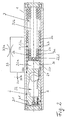
- the door closing mechanism shown in FIGS. 1 to 3 has a housing 1 on, in which there is a hydraulically damped in a cylindrical bore Piston 2, an auxiliary piston 22 and a spring arrangement 3 are located.
- the piston 2 has a closer shaft 4 which is rotatably mounted in the housing 1 geared, in the case shown connected via a pinion.
- the Pinion consists of a rotatably connected to the closer shaft 4 Pinion 4a and a piston-fixed rack 2a.
- the piston 2 is moved to the right.
- the door closes it moves in the opposite direction, i.e. the pinion 4a or the closer shaft 4 rotates clockwise and the piston 2 is moved to the left.
- the closing spring device 3 consists of a closing spring 3c and two reserve closing springs 3a, 3b.
- the springs 3a, 3b, 3c are compression springs. It deals concentrically arranged helical compression springs.
- the closing spring 3c supports itself with its left end directly on the right end of the piston 2 and with its right end on an auxiliary piston 22.
- the auxiliary piston 22 is received in the cylinder space to the right of the piston 1 and also guided as a hydraulic piston in the cylinder space.
- the reserve closing springs 3a, 3b are each supported with their left end on the Auxiliary piston 22 and with its right end on the right front end of the housing 1 from a housing cover 1r screwed in there.
- the auxiliary piston 22 is cup-shaped and consists of a tubular Piston shirt 22a and a piston crown 22b.
- Piston shirt and piston crown can consist of one part ( Figures 1 to 4) or as e.g. in figure 5 and 6 shown, from 2 parts, the pressure-tight, for. B. by an adhesive or welded connection.
- the diameter of the piston skirt 22a on the piston bottom side End of the piston 22 are made less than in the area in which the piston skirt takes over the axial guidance in the piston.
- the spring elements 3 together with the To arrange auxiliary piston 22 In the variant shown in Figure 1 to 3 the inner reserve closing spring 3a is housed concentrically inside the piston. The left end of the spring 3a is supported against the piston crown 22b. It protrudes from the piston to the right and supports itself with her right End at the housing cover 1r.
- the second reserve closing spring is concentric with spring 3a 3b arranged. It supports itself with its left end against the End face of the piston shirt 22a, with its right end, it is supported against the housing cover 1r.
- the guidance of the auxiliary piston 22 in the cylinder happens via the piston skirt 22a, the left end of which forms the collar 22c.
- the outer diameter of the piston tapers to the left of the collar 22c 22 to the piston outer jacket 22d.
- the closing spring 3c Concentric to the piston outer jacket 22d, the closing spring 3c is arranged.
- the spring 3c is supported with her right end against the collar 22c, with its left end against the right End face of the piston 2.
- the sealing element is located in the piston skirt 22a 23, the hydraulic space 32a opposite the hydraulic space 32b seals.
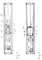
- FIGS. 4 to 6 Another variant for the arrangement of the spring elements 3 and the auxiliary piston 22 is shown in Figures 4 to 6:
- the auxiliary piston 22 is compared to Figure 1 to 3 rotated by 180 ° so that the piston crown 22b points to the right.
- the concentric Reserve springs 3a and 3b support each other with their left ends the piston crown, with its right ends against the housing cover 1r.
- the closing spring 3c is concentric in the interior of the auxiliary piston 22 attached to this. Its right end is supported from the inside against the piston crown 22b, its left end against the right face of the piston 2.
- This Arrangement offers the advantage over the arrangement in FIGS. 1 to 3 that the sealing element 23 arranged in the piston skirt 22a only over a cylinder surface is moved, which do not come into contact with the closing spring 3c can.
- the closing spring 3c could damage the cylinder wall surface in FIGS. 1 to 3 and thus impair the functionality of the sealing element 23.
- the cylinder interior and the interior of the pistons 2 and 22 are filled with hydraulic oil ( Figures 1 to 6).
- the piston 2 has a sealing element 2d (preferably made of elastomer material) and divides the cylinder space into a hydraulic space 31 to the left of the sealing element 2d and a hydraulic space 32 to the right of the sealing element.
- the hydraulic space 32 is in turn divided by the sealing element 23 (preferably made of elastomer material) into a space 32a, which receives the closing spring 3c, and a space 32b, which receives the reserve springs 3a and 3b.
- the hydraulic chamber 31 is connected to the hydraulic chamber 32 via hydraulic channels 36 (FIG. 8) which contain flow valves for regulating the closing and opening speed, as is known in conventional door closers.
- a spring-loaded check valve is in the left end face of the piston 2 2b arranged, which opens during the opening movement when the Piston 2 is moved to the right in the illustration in the figures.
- a pressure relief valve 2c in the piston 2 arranged.
- the sealing element 23 can either, as shown in Figures 1 to 4, in the piston skirt 22a or, as shown in FIG. 5, to a suitable one Place in the cylinder bore.
- An overflow channel 33 is provided for hydraulic control of the auxiliary piston 22 formed which connects the hydraulic spaces 32a and 32b.
- the overflow channel contains a throttle, preferably an adjustable regulating valve 33a, with which is the flow rate of the hydraulic fluid through the channel and thus the speed of movement of the auxiliary piston can be adjusted can.
- a shut-off valve 33b in the overflow channel is closed when the Door has reached its end position during the closing process.
- a spring-loaded check valve 24 is provided, which is for overflowing the hydraulic fluid from room 32b opens into space 32a when the auxiliary piston 22 is moved to the right.
- the door closer shown works as follows. The door is opened by Hand opened. The closer shaft rotates counterclockwise with the pinion 4a and the piston 2 is forced to the right against the action of Closing spring device 3 moved. The initial position in Figure 1 of the auxiliary piston 22 abutting the piston 1 is carried to the right and compresses the reserve closing springs 3a, 3b. The one in the biased position built-in closing spring 3c remains in its pretensioned position.
- the check valve opens 24, so that the hydraulic oil displaced by the piston movement can flow into space 32b into space 32a.
- the piston 2 and the auxiliary piston 22 reach each the right end position, in which the reserve closing springs 3a, 3b are maximally compressed are.
- the closing process then takes place under the action of the closing spring device 3 automatically.
- the door should move quickly and with greater force be accelerated.
- This high-speed phase I lasts e.g. 2 seconds.
- the hydraulic space 32b with the hydraulic space 32a is through the groove 37a connected ( Figure 7), which causes a hydraulic short circuit.
- This allows the hydraulic fluid to flow from space 32b into space 32a and the reserve closing springs 3a, 3b move the auxiliary piston with a large one Force left.
- the movement of the auxiliary piston is via the closing spring 3c transferred to the main piston; at the same time the closing spring presses the Main piston also to the left.
- the auxiliary piston 22 moves in one Slow-running phase II in accordance with the setting of the throttle valve 33 the force of the reserve closing springs 3a, 3b very slowly to the left.
- the sealing element 23 in the auxiliary piston 22 is located on the web between the groove 37a and the groove 37b. The hydraulic fluid displaced by the movement of the auxiliary piston 22 can now only through the overflow channel 33 from the hydraulic room 32b get into the hydraulic space 32a.
- the piston 2 moves during the slow-running phase of the auxiliary piston 22 essentially under the action of the relatively weak closing spring 3c. This That is, the piston 2 runs before the auxiliary piston accelerated or faster.
- the speed of movement of the auxiliary piston is in the slow speed phase II damped by the regulating valve 33a located in the overflow channel 33; this speed can be adjusted with the regulating valve.
- This is e.g. B. set so that the entire slow speed phase II of Auxiliary piston 22 is approx. 25 sec.
- the shut-off valve 33b is open when the door is open. As soon as the piston 2 its left end position is reached when the door is closed via a corresponding one Mechanism, the shut-off valve 33b in the overflow channel 33 is closed.
- the auxiliary piston 22 is hereby in its current position and the remaining energy stored in the reserve springs 3a, 3b remains intact. This means that the slow speed phase is usually premature is stopped.
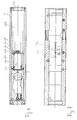
- FIG Figure 5 Another possibility for controlling the movement of the auxiliary piston 22 is in FIG Figure 5 shown.
- the sealing element 23 is located on a corresponding one Place in the cylinder bore and the grooves 37a, 37b are in the piston skirt 22a of the auxiliary piston 22 attached.
- FIG. 8-10 Another way to open and close the flow opening of the Channel 33 is shown in Figures 8-10.
- the shut-off valve 33b is one seal 35 inserted into the piston 2 (preferably made of elastomer material) available.
- the piston 2 is guided so that it is not about its longitudinal axis can twist.
- the seal 35 is attached so that it is in the left End position of the piston 2 with the door closed, the mouth 33c of the overflow channel 33 closes in the hydraulic space 32a. This will Overflow channel 33 between the hydraulic spaces 32b and 32a closed and the auxiliary piston 22 is blocked hydraulically.
- the seal 35 can additionally supported in its effect by a stored spring element become.
- the overflow channel 33 can be designed so that the deep hole 36 is closed at a suitable point by a plug 34.
- a plug 34 In Figure 8 are located on the right of the plug of the overflow channel 33 (as Part of the deep hole), the mouth 33c and the adjustable regulating valve 33a.
- To the left of the sealing plug 34 is the hydraulic circuit known per se for the piston 2 to control the end stroke and the shutter speed.
- the overflow channel mouth is closed 33c through the sealing element 2d embedded in the piston 2. The overflow channel mouth 33c is then in the closed position of the piston 2 on the sealing element 2d.
- the swing energy of the door can then store the already pre-tensioned reserve energy reload, which is simultaneously the opening movement of the door dampened and the user the end of the door opening angle by increased Opening resistance signals.
- the hydraulic chamber 32 has a particularly high operating pressure (approx. 50 bar) there is a special seal of the drive shaft 4 in the housing 1 required, to prevent leakage of the hydraulic oil from the housing.
- the closing spring 3c is weaker as the sum of the reserve closing springs 3a, 3b connected in parallel.
- the closing spring 3c is designed so that during normal operation, if not special Closing resistance, e.g. in the form of wind pressure or obstacles in the There is a closing path, is able to close the door completely, i.e. to move the piston 2 to its left end position before the auxiliary piston 22 has completed its slow-running phase II and therefore before the reserve energy store with the reserve spring 3a, 3b substantially discharged is.
- a sensor device instead of the time-dependent control of the auxiliary piston 22 is provided with control via a sensor device be the hydraulic locking or deceleration of the auxiliary piston 22nd by driving valve 33a or 33b if the door is not working properly closes.
- a sensor device can, for. B. designed in this way be that it monitors the pressure in the hydraulic space 31 by the Pressure drop detected when the closing process is interrupted, before the door is fully closed. This pressure drop always occurs when the door is stopped during the closing process.
- About the pressure drop can e.g. B. a hydraulic control piston operated in a hydraulic Connection system can be arranged, the front and rear connects the hydraulic chambers 31, 32a or 32b formed in the piston 2. The hydraulic The piston can then act on the valve under the effect of the pressure drop Switch 33a or 33b.
- Sensor devices can also be used to detect the door movement or correspondingly moving components of the door closer during the closing process or a delay or stopping the closing movement before reaching it the end position.
- the closing spring device and the reserve spring device can each be made of be composed of a different number of springs.
Landscapes
- Closing And Opening Devices For Wings, And Checks For Wings (AREA)
- Power-Operated Mechanisms For Wings (AREA)
Claims (29)
- Fermeture de porte pour une porte à un battant, de préférence à battant tournant, par exemple à battant pivotant avec arrêt sur face d'appui, à battant pendulaire ou un type analogue,caractérisée en ce que,avec un accumulateur d'énergie (2, 3c, 22, 3a, 3b) pour fermer le battant de porte, à ressort de fermeture (3a, 3b, 3c) de préférence, l'accumulateur d'énergie (2, 3c, 22, 3a, 3b) étant au moins partiellement comprimé par l'ouverture du battant de porte, et au moins partiellement décomprimé à la fermeture,l'accumulateur d'énergie comportant un premier accumulateur partiel d'énergie (2, 3c) et un deuxième accumulateur partiel d'énergie (22, 3a, 3b), la fermeture en fonctionnement normal étant réalisée par la détente du premier accumulateur partiel d'énergie (2, 3c), cette fermeture étant soutenue si nécessaire par la détente du deuxième accumulateur partiel d'énergie (22, 3a, 3b),le premier accumulateur partiel d'énergie (2, 3c) comprenant un dispositif à cylindre et piston (1, 2), avec un premier piston (22) monté de façon étanche dans un cylindre, le deuxième accumulateur partiel d'énergie (22, 3a, 3b) comprenant un dispositif à cylindre et piston (1, 22), avec un deuxième piston (22) monté de façon étanche dans un cylindre,et, de préférence, avec un système, qui est prévu, de régulation ou de réglage de la vitesse de fermeture et/ou d'ouverture, par exemple un système d'amortissement (33, 33a, 33b), qui sera de préférence un système d'amortissement hydraulique ou pneumatique, comportant en particulier un dispositif à piston et cylindre,le deuxième accumulateur partiel d'énergie (22, 3a, 3b) est mis en charge par l'ouverture manuelle du battant de la porte,en soutien de l'effet de fermeture, un dispositif hydraulique de pilotage est prévu pour piloter la détente du deuxième accumulateur partiel d'énergie (22, 3a, 3b), en pilotant la détente du deuxième accumulateur partiel d'énergie (22, 3a, 3b) en dépendance par rapport à un système temporisé (33a, 37a, 37b), et/ou en dépendance par rapport à un système de capteurs supervisant l'opération de fermeture,le dispositif hydraulique de pilotage présentant les caractéristiques suivantes :le dispositif hydraulique de pilotage comprend un dispositif d'écoulement (33, 33a, 33b) relié à la chambre hydraulique (32b) du deuxième accumulateur partiel d'énergie (22, 3a, 3b),le dispositif d'écoulement comprend un dispositif constituant une résistance à l'écoulement conçue de façon telle que, lors d'une première phase du processus de fermeture, le deuxième piston (22) ait une course ralentie derrière le premier piston (2), qui se déplace sous l'effet du premier accumulateur partiel d'énergie (2, 3c),le dispositif d'écoulement comprend un canal d'écoulement (33),avec une embouchure (33c) agissant en association avec le premier piston (2) et qui, à l'arrivée de la porte dans sa position de fermeture, et/ou à l'arrivée du premier piston (2) dans une certaine position, est obturée par ce dernier et arrête le mouvement du deuxième piston (22), en emmagasinant l'énergie résiduelle du deuxième accumulateur partiel d'énergie (22, 3a, 3b) en vue de la prochaine opération de fermeture.
- Fermeture de porte selon la revendication 1, caractérisée en ce que la détente du deuxième accumulateur partiel d'énergie (22, 3a, 3b) est pilotée, sous la dépendance du système temporisé (33a, 37a, 37b), de manière à assurer la fermeture complète de la porte dans un temps prédéterminé après l'ouverture.
- Fermeture de porte selon la revendication 2, caractérisée en ce que le système temporisé (33a), ou plutôt le temps prédéterminé, est réglable.
- Fermeture de porte selon l'une des revendications précédentes, caractérisée en ce que la détente ou une détente renforcée du deuxième accumulateur partiel d'énergie (22, 3a, 3b) est initiée automatiquement si la position de fermeture de la porte n'est pas atteinte après un temps déterminé, ou encore si le système de capteurs supervisant le processus de fermeture le déclenche.
- Fermeture de porte selon l'une des revendications précédentes, caractérisée en ce que la détente du deuxième accumulateur partiel d'énergie (22, 3a, 3b) est interrompue dès que la position de fermeture, ou une position d'ouverture de porte proche de la position de fermeture, est atteinte, étant dans cela de préférence prévu que la décharge du deuxième accumulateur partiel d'énergie sera stoppée si cette position est atteinte avant la fin de la temporisation.
- Fermeture de porte selon l'une des revendications précédentes, caractérisée en ce que la détente du deuxième accumulateur partiel d'énergie (22, 3a, 3b) s'effectue, lors du processus de fermeture, de manière continue au moins dans un domaine d'ouverture de porte déterminé, toutefois plus lentement que la détente du premier accumulateur partiel d'énergie (2, 3c), et/ou avec des phases de détente comportant des vitesses de détente (I, II, III) différenciées.
- Fermeture de porte selon la revendication 6, caractérisée en ce que la dernière phase de détente (III) du deuxième accumulateur partiel d'énergie (22, 3a, 3b), qui se déroule avant l'arrivée en position finale de fermeture, comporte une vitesse de détente (III) relativement élevée en comparaison avec la vitesse de détente du premier accumulateur partiel d'énergie (2, 3c), et/ou en comparaison avec la vitesse de détente (I, II) du deuxième accumulateur partiel d'énergie (22, 3a, 3b) au cours d'une ou plusieurs phases de détente (I, II) précédentes.
- Fermeture de porte selon les revendications 6 ou 7, caractérisée en ce que la dernière phase de détente (III) du deuxième accumulateur partiel d'énergie (22, 3a, 3b), qui se déroule avant l'arrivée en position finale de fermeture, succède à une phase de détente (II) comportant une vitesse de détente (II) relativement lente.
- Fermeture de porte selon la revendication 8, caractérisée en ce que la phase de détente (II) du deuxième accumulateur partiel d'énergie (22, 3a, 3b), qui se déroule à une vitesse de détente (II) relativement lente, est précédée d'une phase de détente (I) comportant une vitesse de détente relativement élevée.
- Fermeture de porte selon l'une des revendications précédentes, caractérisée en ce que le premier piston (2) et le deuxième piston (22) sont guidés dans un cylindre commun (1), montés de préférence l'un après l'autre.
- Fermeture de porte selon la revendication 10, caractérisée en ce que le deuxième piston (22) est conçu en tant que piston (22) hydraulique ou pneumatique, que l'on peut piloter au moyen d'un robinet (33a, 33b) monté dans un dispositif d'écoulement (33), et en particulier bloquer et/ou fixer en position.
- Fermeture de porte selon les revendications 10 ou 11, caractérisée en ce que le deuxième piston (22) peut être piloté pneumatiquement ou hydrauliquement par l'intermédiaire du système temporisé (33a, 37a, 37b).
- Fermeture de porte selon les revendications 11 ou 12, caractérisée en ce que le système temporisé consiste en un dispositif d'écoulement reliant une chambre cylindrique (32a) constituée devant le deuxième piston (22), à une chambre cylindrique (32b) constituée derrière le deuxième piston (22), le système temporisé étant dans cela préférentiellement un robinet d'écoulement (33a), en particulier un robinet d'écoulement (33a) réglable, et/ou un canal d'écoulement (33), et/ou une rainure d'écoulement (37a, 37b), dans le cylindre et/ou dans le deuxième piston (22).
- Fermeture de porte selon l'une des revendications précédentes, caractérisée en ce que, selon la position du deuxième piston (22), une résistance à l'écoulement différente est en circuit dans le dispositif d'écoulement, ou plutôt des dispositifs à résistance d'écoulement différenciée (33a, 37a, 37b) sont activés successivement.
- Fermeture de porte selon l'une des revendications 12 à 14, caractérisée en ce que la vitesse de déplacement du deuxième piston (22) est pilotée par une rainure d'écoulement (37a, 37b) aménagée dans la face externe de la paroi du piston, ou dans la face interne de la paroi du cylindre.
- Fermeture de porte selon l'une des revendications 12 à 15, caractérisée en ce que la vitesse de déplacement du deuxième piston (22) est pilotée par un canal d'écoulement (33) aménagé dans le cylindre ou le piston.
- Fermeture de porte selon la revendication 16, caractérisée en ce que un robinet de régulation (33a) et/ou un dispositif d'arrêt, par exemple un robinet d'arrêt (33b), sont insérés dans le canal d'écoulement (33).
- Fermeture de porte selon la revendication 17, caractérisée en ce que le robinet d'arrêt (33b), lorsque la position de fermeture de la porte est atteinte, et/ou une position déterminée du premier piston (2) est atteinte, de préférence la position du premier piston (2) de fin de fermeture, arrête le mouvement du deuxième piston (22) automatiquement, de préférence en emmagasinant l'énergie résiduelle du deuxième accumulateur partiel d'énergie (22, 3a, 3b) en vue de la prochaine opération de fermeture.
- Fermeture de porte selon la revendication 1, caractérisée en ce que le premier piston (2) comporte un joint (35) agissant en association avec l'embouchure (33c) du canal d'écoulement dans le cylindre, constitué de préférence d'un élément d'étanchéité (35) placé dans un logement en creux, de préférence un trou borgne, du premier piston, l'élément d'étanchéité étant de préférence mis en charge par un ressort.
- Fermeture de porte selon l'une des revendications précédentes, caractérisée en ce que le premier piston (2) et le deuxième piston (22) créent dans l'espace intérieur du cylindre, des chambres hydrauliques (31, 32a, 32b) reliées hydrauliquement entre elles de telle sorte que des pressions hydrauliques différentes (P1, P2, P3) s'établissent dans les chambres, et avec cela, une première chambre (31) se forme devant le premier piston (2), une deuxième chambre (32a) entre le premier piston (2) et le deuxième piston (22), et une troisième chambre (32b) derrière le deuxième piston (22), la pression étant lors de la fermeture plus élevée dans la première chambre (31) que dans la deuxième chambre (32a), et dans la deuxième chambre (32a) plus élevée que dans la troisième chambre (32b).
- Fermeture de porte selon l'une des revendications précédentes, caractérisée en ce que un arbre mené (4) est lié dans son action au premier piston (2), de préférence par l'intermédiaire d'un entraínement à engrenage, par exemple d'une crémaillère (2a) du côté du piston et d'un pignon (4a) du côté de l'arbre mené.
- Fermeture de porte selon la revendication 21, caractérisée en ce que l'arbre mené (4) est monté dans le boítier du cylindre de façon à être libre en rotation, avec une étanchéité assurée par un joint pour hautes pressions, de préférence pour des pressions hydrauliques > 10 bars, de préférence pour environ 50 bars.
- Fermeture de porte selon l'une des revendications précédentes, caractérisée en ce que le premier accumulateur partiel d'énergie (2, 3c) comprend un dispositif à cylindre et pistons (2, 31, 32), avec un premier piston (2) guidé de façon étanche dans un cylindre (31, 32), ce piston (2) étant de préférence hydraulique, et le deuxième accumulateur partiel d'énergie (22, 3a, 3b) comprend une pièce d'appui, de préférence du genre coupelle de ressort, guidée dans un cylindre et sur laquelle le deuxième accumulateur partiel d'énergie (22, 3a, 3b) prend appui, le deuxième accumulateur partiel d'énergie agissant en association avec un dispositif de blocage que l'on peut piloter, et qui bloque la pièce d'appui, de préférence mécaniquement.
- Fermeture de porte selon la revendication 23, caractérisée en ce que le dispositif de blocage comprend un dispositif de verrouillage agissant en association avec la pièce d'appui du deuxième accumulateur partiel d'énergie (22, 3a, 3b).
- Fermeture de porte selon la revendication 24, caractérisée en ce que le dispositif de verrouillage est conçu en tant que verrouillage à billes.
- Fermeture de porte selon les revendications 23 à 25, caractérisée en ce que la pièce d'appui du deuxième accumulateur partiel d'énergie (22, 3a, 3b) et/ou le dispositif de blocage agissent en association avec le système de capteurs, ce en quoi le système de capteurs saisit la pression et/ou une variation de pression dans une chambre de pression du dispositif à cylindre et pistons du premier accumulateur partiel d'énergie.
- Fermeture de porte selon l'une des revendications précédentes, caractérisée en ce que le premier accumulateur partiel d'énergie (2, 3c) comprend, en tant qu'élément d'emmagasinage d'énergie, un premier dispositif de fermeture à ressort (3c), et le deuxième accumulateur partiel d'énergie (22, 3a, 3b) comprend, en tant qu'élément d'emmagasinage d'énergie, un deuxième dispositif de fermeture à ressort (3a, 3b).
- Fermeture de porte selon la revendication 27, caractérisée en ce que le premier dispositif de fermeture à ressort (3c) comprend un ressort d'une force inférieure à celle du deuxième dispositif de fermeture à ressort (3a, 3b).
- Fermeture de porte selon les revendications 27 ou 28, caractérisée en ce que le premier dispositif de fermeture à ressort (3c) est en appui, d'un côté, sur le piston (2) du premier accumulateur partiel d'énergie, et de l'autre côté, sur la pièce d'appui, c'est à dire le piston (22), du deuxième accumulateur partiel d'énergie, ou en butée directe sur le cylindre, et le deuxième dispositif de fermeture à ressort (3a, 3b) est en appui, d'un côté, sur la pièce d'appui, c'est à dire le piston (22), du deuxième accumulateur partiel d'énergie, et de l'autre côté en butée sur le cylindre.
Applications Claiming Priority (4)
| Application Number | Priority Date | Filing Date | Title |
|---|---|---|---|
| DE19509621 | 1995-03-21 | ||
| DE19509621 | 1995-03-21 | ||
| DE19608023 | 1996-03-01 | ||
| DE19608023 | 1996-03-01 |
Publications (2)
| Publication Number | Publication Date |
|---|---|
| EP0733763A1 EP0733763A1 (fr) | 1996-09-25 |
| EP0733763B1 true EP0733763B1 (fr) | 2000-08-16 |
Family
ID=26013445
Family Applications (1)
| Application Number | Title | Priority Date | Filing Date |
|---|---|---|---|
| EP19960104540 Expired - Lifetime EP0733763B1 (fr) | 1995-03-21 | 1996-03-21 | Ferme-porte |
Country Status (2)
| Country | Link |
|---|---|
| EP (1) | EP0733763B1 (fr) |
| DE (2) | DE59605738D1 (fr) |
Cited By (1)
| Publication number | Priority date | Publication date | Assignee | Title |
|---|---|---|---|---|
| CN105041100A (zh) * | 2014-04-15 | 2015-11-11 | 盖慈有限公司 | 门驱动装置 |
Families Citing this family (7)
| Publication number | Priority date | Publication date | Assignee | Title |
|---|---|---|---|---|
| CN101469587B (zh) * | 2007-12-28 | 2013-03-13 | 盖泽工业(天津)有限公司 | 用于马达驱动的摆动门扇的安全系统 |
| EP2304149B1 (fr) * | 2008-05-19 | 2015-01-21 | Helmut Katherl | Dispositif pour le déplacement automatique d'un vantail d'une fenêtre ou d'une porte comportant un accumulateur à ressort |
| DE102014207217B3 (de) * | 2014-04-15 | 2015-02-19 | Geze Gmbh | Drehtürantrieb |
| EP2933414A1 (fr) * | 2014-04-15 | 2015-10-21 | GEZE GmbH | Entraînement de porte |
| DK2933415T3 (en) * | 2014-04-15 | 2017-01-23 | Geze Gmbh | A door operator |
| DE102018202783A1 (de) * | 2018-02-23 | 2019-08-29 | Geze Gmbh | Antrieb für einen Flügel einer Tür oder eines Fensters |
| DE102018122289A1 (de) | 2018-09-12 | 2020-03-12 | Hettich-Oni Gmbh & Co. Kg | Vorrichtung zum mechanischen Schließen eines bewegbaren Möbelteils und Verfahren zum Öffnen und Schließen eines bewegbaren Möbelteils |
Family Cites Families (4)
| Publication number | Priority date | Publication date | Assignee | Title |
|---|---|---|---|---|
| US3561036A (en) * | 1968-06-24 | 1971-02-09 | Rixson Inc | Hold-open apparatus for door |
| DE3203390C2 (de) * | 1982-02-02 | 1986-12-11 | BKS Sicherheitstechnik GmbH, 5040 Brühl | Zahntrieb-Türschließer |
| DE3423242C1 (de) * | 1984-06-23 | 1985-11-07 | Dorma-Baubeschlag Gmbh & Co Kg, 5828 Ennepetal | Selbsttaetiger Tuerschliesser |
| DE4237179C2 (de) * | 1992-11-04 | 2002-01-31 | Geze Gmbh | Türschließer |
-
1996
- 1996-03-21 DE DE59605738T patent/DE59605738D1/de not_active Expired - Fee Related
- 1996-03-21 EP EP19960104540 patent/EP0733763B1/fr not_active Expired - Lifetime
- 1996-03-21 DE DE1996111203 patent/DE19611203A1/de not_active Withdrawn
Cited By (2)
| Publication number | Priority date | Publication date | Assignee | Title |
|---|---|---|---|---|
| CN105041100A (zh) * | 2014-04-15 | 2015-11-11 | 盖慈有限公司 | 门驱动装置 |
| CN105041100B (zh) * | 2014-04-15 | 2017-12-08 | 盖慈有限公司 | 门驱动装置 |
Also Published As
| Publication number | Publication date |
|---|---|
| EP0733763A1 (fr) | 1996-09-25 |
| DE59605738D1 (de) | 2000-09-21 |
| DE19611203A1 (de) | 1996-09-26 |
Similar Documents
| Publication | Publication Date | Title |
|---|---|---|
| EP0662185B1 (fr) | Mecanisme d'entrainement d'une porte battante | |
| EP0715675B1 (fr) | Mecanisme d'entrainement d'une porte battante | |
| EP0166285B1 (fr) | Ferme-porte automatique | |
| DE69001591T2 (de) | Türschliesser. | |
| DE4034188C2 (fr) | ||
| EP1431496A2 (fr) | Entraínement servo-électrohydraulique pour commande de porte, fenêtre ou similaire | |
| EP0137861B1 (fr) | Ferme-porte automatique | |
| DE19538482C1 (de) | Hydraulischer Servotürschließer | |
| DE202008005721U1 (de) | Türschließer mit einer hydraulischen Schließverzögerung | |
| DE3234319C2 (fr) | ||
| EP0733763B1 (fr) | Ferme-porte | |
| EP0972902B1 (fr) | Ferme-porte à dimensions réduites | |
| DE102016208099B4 (de) | Antrieb für eine tür | |
| DE102014222210B3 (de) | Antrieb für eine Tür oder ein Fenster | |
| CH689055A5 (de) | Drehtuerantrieb. | |
| DD269588A5 (de) | Teleskoparm, insbesondere fuer ueber schwenkarme betaetigte, durch kippen sich mit der fahrzeugkarosserie verriegelnde aussenschwenktueren von fahrzeugen | |
| DE19607878B4 (de) | Drehtürantrieb | |
| DE4323151C5 (de) | Drehtürantrieb | |
| EP2518251A2 (fr) | Ferme-porte | |
| DE10361085B4 (de) | Hydraulisch-mechanische Schließfolgeregelung | |
| DE29605310U1 (de) | Türschließer | |
| EP0328917B1 (fr) | Ferme-porte | |
| DE2721974A1 (de) | Tuerschliesser | |
| DE19524776A1 (de) | Türschließer mit hydraulischer Dämpfung | |
| EP0879336B1 (fr) | Ferme-porte programmable |
Legal Events
| Date | Code | Title | Description |
|---|---|---|---|
| PUAI | Public reference made under article 153(3) epc to a published international application that has entered the european phase |
Free format text: ORIGINAL CODE: 0009012 |
|
| AK | Designated contracting states |
Kind code of ref document: A1 Designated state(s): CH DE ES FR GB IT LI |
|
| 17P | Request for examination filed |
Effective date: 19970315 |
|
| 17Q | First examination report despatched |
Effective date: 19981218 |
|
| RAP1 | Party data changed (applicant data changed or rights of an application transferred) |
Owner name: GEZE GMBH |
|
| GRAG | Despatch of communication of intention to grant |
Free format text: ORIGINAL CODE: EPIDOS AGRA |
|
| RAP3 | Party data changed (applicant data changed or rights of an application transferred) |
Owner name: GEZE GMBH |
|
| GRAG | Despatch of communication of intention to grant |
Free format text: ORIGINAL CODE: EPIDOS AGRA |
|
| GRAH | Despatch of communication of intention to grant a patent |
Free format text: ORIGINAL CODE: EPIDOS IGRA |
|
| GRAH | Despatch of communication of intention to grant a patent |
Free format text: ORIGINAL CODE: EPIDOS IGRA |
|
| GRAA | (expected) grant |
Free format text: ORIGINAL CODE: 0009210 |
|
| AK | Designated contracting states |
Kind code of ref document: B1 Designated state(s): CH DE ES FR GB IT LI |
|
| PG25 | Lapsed in a contracting state [announced via postgrant information from national office to epo] |
Ref country code: ES Free format text: THE PATENT HAS BEEN ANNULLED BY A DECISION OF A NATIONAL AUTHORITY Effective date: 20000816 |
|
| REG | Reference to a national code |
Ref country code: CH Ref legal event code: NV Representative=s name: E. BLUM & CO. PATENTANWAELTE Ref country code: CH Ref legal event code: EP |
|
| ITF | It: translation for a ep patent filed | ||
| REF | Corresponds to: |
Ref document number: 59605738 Country of ref document: DE Date of ref document: 20000921 |
|
| GBT | Gb: translation of ep patent filed (gb section 77(6)(a)/1977) |
Effective date: 20000915 |
|
| ET | Fr: translation filed | ||
| PGFP | Annual fee paid to national office [announced via postgrant information from national office to epo] |
Ref country code: GB Payment date: 20010214 Year of fee payment: 6 |
|
| PGFP | Annual fee paid to national office [announced via postgrant information from national office to epo] |
Ref country code: CH Payment date: 20010219 Year of fee payment: 6 |
|
| PGFP | Annual fee paid to national office [announced via postgrant information from national office to epo] |
Ref country code: FR Payment date: 20010313 Year of fee payment: 6 Ref country code: DE Payment date: 20010313 Year of fee payment: 6 |
|
| PLBE | No opposition filed within time limit |
Free format text: ORIGINAL CODE: 0009261 |
|
| STAA | Information on the status of an ep patent application or granted ep patent |
Free format text: STATUS: NO OPPOSITION FILED WITHIN TIME LIMIT |
|
| 26N | No opposition filed | ||
| REG | Reference to a national code |
Ref country code: GB Ref legal event code: IF02 |
|
| PG25 | Lapsed in a contracting state [announced via postgrant information from national office to epo] |
Ref country code: GB Free format text: LAPSE BECAUSE OF NON-PAYMENT OF DUE FEES Effective date: 20020321 |
|
| PG25 | Lapsed in a contracting state [announced via postgrant information from national office to epo] |
Ref country code: LI Free format text: LAPSE BECAUSE OF NON-PAYMENT OF DUE FEES Effective date: 20020331 Ref country code: CH Free format text: LAPSE BECAUSE OF NON-PAYMENT OF DUE FEES Effective date: 20020331 |
|
| PG25 | Lapsed in a contracting state [announced via postgrant information from national office to epo] |
Ref country code: DE Free format text: LAPSE BECAUSE OF NON-PAYMENT OF DUE FEES Effective date: 20021001 |
|
| GBPC | Gb: european patent ceased through non-payment of renewal fee |
Effective date: 20020321 |
|
| REG | Reference to a national code |
Ref country code: CH Ref legal event code: PL |
|
| PG25 | Lapsed in a contracting state [announced via postgrant information from national office to epo] |
Ref country code: FR Free format text: LAPSE BECAUSE OF NON-PAYMENT OF DUE FEES Effective date: 20021129 |
|
| REG | Reference to a national code |
Ref country code: FR Ref legal event code: ST |
|
| PG25 | Lapsed in a contracting state [announced via postgrant information from national office to epo] |
Ref country code: IT Free format text: LAPSE BECAUSE OF NON-PAYMENT OF DUE FEES;WARNING: LAPSES OF ITALIAN PATENTS WITH EFFECTIVE DATE BEFORE 2007 MAY HAVE OCCURRED AT ANY TIME BEFORE 2007. THE CORRECT EFFECTIVE DATE MAY BE DIFFERENT FROM THE ONE RECORDED. Effective date: 20050321 |