EP0733029B1 - Kompostierungsanlage für organische abfälle und verfahren zur kompostierung dieser abfälle - Google Patents
Kompostierungsanlage für organische abfälle und verfahren zur kompostierung dieser abfälle Download PDFInfo
- Publication number
- EP0733029B1 EP0733029B1 EP95902074A EP95902074A EP0733029B1 EP 0733029 B1 EP0733029 B1 EP 0733029B1 EP 95902074 A EP95902074 A EP 95902074A EP 95902074 A EP95902074 A EP 95902074A EP 0733029 B1 EP0733029 B1 EP 0733029B1
- Authority
- EP
- European Patent Office
- Prior art keywords
- zone
- waste
- agitator
- plant
- composting
- Prior art date
- Legal status (The legal status is an assumption and is not a legal conclusion. Google has not performed a legal analysis and makes no representation as to the accuracy of the status listed.)
- Expired - Lifetime
Links
- 238000000034 method Methods 0.000 title claims abstract description 37
- 238000009264 composting Methods 0.000 title claims abstract description 28
- 239000002699 waste material Substances 0.000 title claims abstract description 28
- 239000010815 organic waste Substances 0.000 title claims abstract description 8
- 239000002361 compost Substances 0.000 claims abstract description 24
- QVGXLLKOCUKJST-UHFFFAOYSA-N atomic oxygen Chemical compound [O] QVGXLLKOCUKJST-UHFFFAOYSA-N 0.000 claims abstract description 10
- 239000001301 oxygen Substances 0.000 claims abstract description 10
- 229910052760 oxygen Inorganic materials 0.000 claims abstract description 10
- 239000002023 wood Substances 0.000 claims abstract description 9
- 239000011368 organic material Substances 0.000 claims abstract description 7
- XLYOFNOQVPJJNP-UHFFFAOYSA-N water Substances O XLYOFNOQVPJJNP-UHFFFAOYSA-N 0.000 claims abstract description 7
- 238000005273 aeration Methods 0.000 claims abstract description 6
- 238000007781 pre-processing Methods 0.000 claims abstract description 6
- 239000010791 domestic waste Substances 0.000 claims abstract description 4
- 210000003608 fece Anatomy 0.000 claims abstract description 4
- 239000010871 livestock manure Substances 0.000 claims abstract description 4
- 239000010802 sludge Substances 0.000 claims abstract description 4
- 239000010902 straw Substances 0.000 claims abstract description 4
- 238000007599 discharging Methods 0.000 claims abstract 2
- 238000001035 drying Methods 0.000 claims abstract 2
- 238000000605 extraction Methods 0.000 claims abstract 2
- 239000002994 raw material Substances 0.000 claims description 3
- 239000000725 suspension Substances 0.000 claims description 2
- 239000000463 material Substances 0.000 description 58
- 238000001816 cooling Methods 0.000 description 6
- 238000002156 mixing Methods 0.000 description 4
- 239000002245 particle Substances 0.000 description 3
- QGZKDVFQNNGYKY-UHFFFAOYSA-N Ammonia Chemical compound N QGZKDVFQNNGYKY-UHFFFAOYSA-N 0.000 description 2
- XEEYBQQBJWHFJM-UHFFFAOYSA-N Iron Chemical compound [Fe] XEEYBQQBJWHFJM-UHFFFAOYSA-N 0.000 description 2
- 244000052616 bacterial pathogen Species 0.000 description 2
- 230000005540 biological transmission Effects 0.000 description 2
- 239000007789 gas Substances 0.000 description 2
- 239000002689 soil Substances 0.000 description 2
- 230000000087 stabilizing effect Effects 0.000 description 2
- 239000000126 substance Substances 0.000 description 2
- UGFAIRIUMAVXCW-UHFFFAOYSA-N Carbon monoxide Chemical compound [O+]#[C-] UGFAIRIUMAVXCW-UHFFFAOYSA-N 0.000 description 1
- 235000002918 Fraxinus excelsior Nutrition 0.000 description 1
- QAOWNCQODCNURD-UHFFFAOYSA-N Sulfuric acid Chemical compound OS(O)(=O)=O QAOWNCQODCNURD-UHFFFAOYSA-N 0.000 description 1
- 239000002253 acid Substances 0.000 description 1
- 229910021529 ammonia Inorganic materials 0.000 description 1
- 239000002956 ash Substances 0.000 description 1
- 238000004140 cleaning Methods 0.000 description 1
- 238000010276 construction Methods 0.000 description 1
- 238000011109 contamination Methods 0.000 description 1
- 238000010586 diagram Methods 0.000 description 1
- 230000000694 effects Effects 0.000 description 1
- 230000007613 environmental effect Effects 0.000 description 1
- 239000003337 fertilizer Substances 0.000 description 1
- 239000003546 flue gas Substances 0.000 description 1
- 238000011010 flushing procedure Methods 0.000 description 1
- 238000013467 fragmentation Methods 0.000 description 1
- 238000006062 fragmentation reaction Methods 0.000 description 1
- 239000003205 fragrance Substances 0.000 description 1
- 239000003517 fume Substances 0.000 description 1
- 239000003673 groundwater Substances 0.000 description 1
- 239000003630 growth substance Substances 0.000 description 1
- 238000010438 heat treatment Methods 0.000 description 1
- 229910052742 iron Inorganic materials 0.000 description 1
- 230000001473 noxious effect Effects 0.000 description 1
- 239000003895 organic fertilizer Substances 0.000 description 1
- 230000005019 pattern of movement Effects 0.000 description 1
- 230000000149 penetrating effect Effects 0.000 description 1
- 230000035699 permeability Effects 0.000 description 1
- 238000000746 purification Methods 0.000 description 1
- 238000007790 scraping Methods 0.000 description 1
- 238000007789 sealing Methods 0.000 description 1
- 239000007787 solid Substances 0.000 description 1
- 238000003756 stirring Methods 0.000 description 1
- 235000011149 sulphuric acid Nutrition 0.000 description 1
- 239000001117 sulphuric acid Substances 0.000 description 1
- 230000007306 turnover Effects 0.000 description 1
- 238000005406 washing Methods 0.000 description 1
- 238000004065 wastewater treatment Methods 0.000 description 1
Images


Classifications
-
- F—MECHANICAL ENGINEERING; LIGHTING; HEATING; WEAPONS; BLASTING
- F24—HEATING; RANGES; VENTILATING
- F24V—COLLECTION, PRODUCTION OR USE OF HEAT NOT OTHERWISE PROVIDED FOR
- F24V99/00—Subject matter not provided for in other main groups of this subclass
-
- C—CHEMISTRY; METALLURGY
- C05—FERTILISERS; MANUFACTURE THEREOF
- C05F—ORGANIC FERTILISERS NOT COVERED BY SUBCLASSES C05B, C05C, e.g. FERTILISERS FROM WASTE OR REFUSE
- C05F17/00—Preparation of fertilisers characterised by biological or biochemical treatment steps, e.g. composting or fermentation
- C05F17/10—Addition or removal of substances other than water or air to or from the material during the treatment
-
- C—CHEMISTRY; METALLURGY
- C05—FERTILISERS; MANUFACTURE THEREOF
- C05F—ORGANIC FERTILISERS NOT COVERED BY SUBCLASSES C05B, C05C, e.g. FERTILISERS FROM WASTE OR REFUSE
- C05F17/00—Preparation of fertilisers characterised by biological or biochemical treatment steps, e.g. composting or fermentation
- C05F17/90—Apparatus therefor
- C05F17/914—Portable or transportable devices, e.g. transport containers or trucks
-
- C—CHEMISTRY; METALLURGY
- C05—FERTILISERS; MANUFACTURE THEREOF
- C05F—ORGANIC FERTILISERS NOT COVERED BY SUBCLASSES C05B, C05C, e.g. FERTILISERS FROM WASTE OR REFUSE
- C05F17/00—Preparation of fertilisers characterised by biological or biochemical treatment steps, e.g. composting or fermentation
- C05F17/90—Apparatus therefor
- C05F17/921—Devices in which the material is conveyed essentially horizontally between inlet and discharge means
- C05F17/939—Means for mixing or moving with predetermined or fixed paths, e.g. rails or cables
-
- C—CHEMISTRY; METALLURGY
- C05—FERTILISERS; MANUFACTURE THEREOF
- C05F—ORGANIC FERTILISERS NOT COVERED BY SUBCLASSES C05B, C05C, e.g. FERTILISERS FROM WASTE OR REFUSE
- C05F17/00—Preparation of fertilisers characterised by biological or biochemical treatment steps, e.g. composting or fermentation
- C05F17/90—Apparatus therefor
- C05F17/964—Constructional parts, e.g. floors, covers or doors
- C05F17/971—Constructional parts, e.g. floors, covers or doors for feeding or discharging materials to be treated; for feeding or discharging other material
- C05F17/979—Constructional parts, e.g. floors, covers or doors for feeding or discharging materials to be treated; for feeding or discharging other material the other material being gaseous
-
- Y—GENERAL TAGGING OF NEW TECHNOLOGICAL DEVELOPMENTS; GENERAL TAGGING OF CROSS-SECTIONAL TECHNOLOGIES SPANNING OVER SEVERAL SECTIONS OF THE IPC; TECHNICAL SUBJECTS COVERED BY FORMER USPC CROSS-REFERENCE ART COLLECTIONS [XRACs] AND DIGESTS
- Y02—TECHNOLOGIES OR APPLICATIONS FOR MITIGATION OR ADAPTATION AGAINST CLIMATE CHANGE
- Y02P—CLIMATE CHANGE MITIGATION TECHNOLOGIES IN THE PRODUCTION OR PROCESSING OF GOODS
- Y02P20/00—Technologies relating to chemical industry
- Y02P20/141—Feedstock
- Y02P20/145—Feedstock the feedstock being materials of biological origin
-
- Y—GENERAL TAGGING OF NEW TECHNOLOGICAL DEVELOPMENTS; GENERAL TAGGING OF CROSS-SECTIONAL TECHNOLOGIES SPANNING OVER SEVERAL SECTIONS OF THE IPC; TECHNICAL SUBJECTS COVERED BY FORMER USPC CROSS-REFERENCE ART COLLECTIONS [XRACs] AND DIGESTS
- Y02—TECHNOLOGIES OR APPLICATIONS FOR MITIGATION OR ADAPTATION AGAINST CLIMATE CHANGE
- Y02W—CLIMATE CHANGE MITIGATION TECHNOLOGIES RELATED TO WASTEWATER TREATMENT OR WASTE MANAGEMENT
- Y02W30/00—Technologies for solid waste management
- Y02W30/40—Bio-organic fraction processing; Production of fertilisers from the organic fraction of waste or refuse
Definitions
- the present invention relates to a composting plant for composting organic material such as household waste separated at the source, organic sludge from waste water treatment plants and industries, wood chippings, straw, farmyard manure, and the invention also relates to a method for composting such waste.
- the simplest way of removing organic waste is a simple waste storage at a refuse dump which, however, may entail serious environmental problems such as pollution of the ground water, gas emission, leachate, odour, contamination, dissemination etc.
- the organic waste can be composted by it being fragmented, mixed and de-posited in a pit or stack. In order to achieve the optimum conditions such as supply of the necessary quantity of oxygen, the waste is aerated from time to time by shifting the stacks.
- the composted waste can be used as a means of soil amelioration. Both cases are energy consuming.
- the waste may otherwise be disposed of by incineration, by which a certain energy output can be re covered. This, however, entails a need for flue gas purification and disposal of the ashes, furthermore the initial costs are rather exorbitant.
- organic waste can be treated in biogas plants, during which inflammable gases are generated.
- the degassed material can be used as organic fertilizer.
- the object of the invention is aimed at providing a simple, reliable and effective composting plant having low establishing and operating costs and having a high degree of stabilizing of the composted waste which upon completion of the process can be utilized as a growth substance described as quality compost.
- From US-A 410 348 is known a plant where the compost material is placed in a pit and is turned from time to time by a special turnover machine.
- From DE-C 36 37 393 is known a plant where the compost material is aerated from the bottom. In none of these cases is the generated heat energy utilized.
- From DE-A 42 08 390 is known a system for removal of odorants in the exhaust fumes from a composting plant.
- WO 931607 discloses an apparatus for producing compost from waste material, the apparatus consisting of an open silo which contains the material bed to be composted.
- the material is moved by mixing elements with spiral parts which work the compost, the said elements moving in the bed during operation.
- Each individual mixing element comprises a rotating shaft part and blades protruding from it. These mixing elements are arranged in pairs.
- the apparatus works in batch mode and emissions from the material are transmitted to the ambient environment.
- EP 0 296 245 A1 discloses a process for composting organic materials, which is carried out in a closed container. Fresh air is fed into the organic materials and the warm moisture-laden outgoing air is conducted away. The customary presence of noxious substances, and in particular the unpleasant odours, is prevented by cooling the outgoing air to condense the moisture it contains.
- the disclosed process works in batch mode and involves that at least emissions are transmitted to the ambient environment, however primarily in form of gasses.
- DE 2541070 A1 discloses a process where organic waste is digested by passing it downwardly through a closed vessel while air is passed upwardly through it process works in batch mode.
- DE 2415695 C2 discloses an apparatus for composting waste material, said apparatus having a bed for holding the composting material. The material is fed into the bed at one end and discharged at the other.
- the apparatus has screw-like agitators for agitating the material and for moving the compost from one end of the silo to the other.
- the apparatus works in batch mode and emissions from the material are transmitted to the ambient environment.
- the object of the invention is to define a composting plant with an active usage of the heat energy generated at the putrefactive process, at the same time achieving a high quality of the finished composted material and without the plant causing any odour nuisance.
- the device for advancing the waste material across the process zone is designed as a driven texturing agitator suspended as a runner above the process zone.
- the protruding spikes of the texturing agitator are arranged in one or more helicals such that the material be moved at a horizontal plane, is lifted, fragmented, textured and homogenized when the agitator runs through the material whereby it is loosened as the material otherwise gradually becomes compressed and obtains a denser texture as a consequence of the advancing putrefaction and thereby renders the aeration difficult.
- the suspension of the texturing agitator is arranged such that it from its downwardly suspended position can be swung up above the waste heap in the residence zone, which increases the movements of the agitator as it at the outlet zone can be swung up and run back above the compost heap.
- the texturing agitator is arranged as an agitator motor, the motor being integrated in the actual agitator.
- the texturing agitator When the agitator in its open position is advanced above the compost heap there is a risk that newly introduced material that might stick to the agitator fails off over composted material such that no absolute guarantee can be given that the material is free from germs.
- This can be counteracted by the texturing agitator first treats, i.e. runs through the compost heap closest to the outlet zone and then treats the remaining compost heap closest to the inlet. Should some newly introduced material happen to drop down over the half-way composted material, then this is of minor significance as this will be sanitarized before arriving at the outlet zone. At the operating temperatures present in the plant the sanitarization lasts from a few hours to 24 hours. It is understood that basically it is a question of only very small quantities that can stick to the agitator.
- Another solution to the problem is to use two texturing agitators where one operates solely at the inlet side and the other at the outlet side. As a possibility a third agitator may be fitted between the two first mentioned exclusively for treating the compost heap in the middle.
- the arranging of the spikes of the texturing agitator, the position of same and the rotation and advancing speed of the agitator are matched such that the material does not fall against the agitator when it runs through the compost heap, but is led from one side of the agitator to the other. Furthermore the spikes lift the material a short distance, this counteracting the heap to compress as mentioned above.
- the texturing mentioned is a turning over of particles causing the particles to be turned relative one another from time to time.
- Another problem in the texturing agitator is that the bottom layer which the agitator runs across becomes smoothed, i.e. is flattened and is made compact such that it becomes increasingly difficult for the air to penetrate the layer. This is counteracted by scrapers underneath the bottom of the agitator not causing the smoothed effect but scrapes up the separating layer. When after a while the separating layer has become too compact it can be loosened by the agitator being lowered a little. After a number of runs the separating layer has been substituted by new material and can then be run again.
- the composting plant may be used for composting organic waste such as household waste separated at the source, sludge, wood chippings, straw, farmyard manure a way where waste is fed into a sealed compartment where it is advanced over a process zone where an aeration is performed up through the waste heap and where the oxygen concentration is necessary for the putrefactive process is kept by intake of fresh air and that a process temperature in the material in the range of 55-62°C is maintained as the surplus heat be extracted from the circulating air in the compartment and after a residence time in the process zone of the approximate duration 5 to 25 days the now composted waste be discharged from the compartment.
- organic waste such as household waste separated at the source, sludge, wood chippings, straw, farmyard manure a way where waste is fed into a sealed compartment where it is advanced over a process zone where an aeration is performed up through the waste heap and where the oxygen concentration is necessary for the putrefactive process is kept by intake of fresh air and that a process temperature in the material in the range of
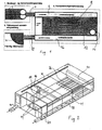
- the plant comprises a receiving and pre-processing plant 2 for the organic material to be composted.
- the material is here subject to a fragmentation before being advanced by a conveyor 4 to an inlet zone 6 in a sealed compartment 8.
- a mixing of various types of raw materials can be performed depending on which type of compost that is required.
- the entrance of the conveyor 4 into the sealed compartment has the shape of a tube and possibly with a reduced cross section 10 (Fig. 2) which is totally filled during the feeding and in which a plug of material is left which seals off the air.
- the material 6 is advanced over a process zone 12 by an especially designed texturing agitator 14 which in a predefined pattern gradually moves the material over to an outlet zone 16 from where the material as finished raw compost is discharged from the compartment.
- a scraper conveyor 18 (Fig. 2) at the bottom of the outlet zone which advances the compost out through a pipe 20 in the compartment and it is possibly advanced further by another conveyor 22 to a collection site 24.
- a plug of compost is left sealing off the air.
- the material is aerated by means of an underlying aerating system whereby an air current is penetrating up through the material.
- the aeration system can be constituted by a perforated tube system 26 laid out directly at the bottom in the compartment. Over the tube system 26 a bottom layer of raw wood chippings 28 (Fig.4) or similar material is laid out at which layer the introduced material lies. The wood chippings protect the tube system as well as the bottom of the texturing agitator 14 which thereby is kept off the solid bottom and the air relatively easily penetrates the wood chippings and enters into the material lying above.
- a bottom of iron sheet can be laid out such that the bottom can be cleaned by a mini digger.
- the tubes in the tube system can start from an air distributor box 30 situated at one end of the compartment as shown in Fig. 2.
- the air is delivered by a ventilator 32 from which the air via two ducts 34 is led to the distributor box 30.
- two ventilators may be present as shown in Fig. 7.
- the mixed and homogeneous material from the receiving and pre-processing plant can be distributed by a distributor plant that can be arranged as a grip arrangement 36 above the zone as shown in Figs. 3-5.
- the arrangement comprises a number of downwardly suspended grips 38 mounted at a reciprocating shaft moved by a hydraulic cylinder.
- the grips are mounted such that they glide or swing up above the material at the return movement of the shaft, but at the for-ward movement are kept down and thereby advances the fed material until it lies as a smooth layer in the entire length of the inlet zone.
- the feeding in Fig. 6 takes place at the top of the compartment, but the grip arrangement is practical in both instances.
- the feeding takes place in a somewhat different way: here the material is advanced by a conveyor 4 up to the roof 40 of the compartment where the material is delivered at a band conveyor 42 terminating above two air locks 44 where the material is delivered for passage into the compartment.
- the band conveyor is arranged such that it can run either direction and deliver the material into the two air locks every alternate turn. In larger plants this improves the distribution of the fed material.
- a texturing agitator 14 as shown in Fig. 8.
- the agitator is suspended in a runner comprising a bar 44 at either side of the compartment between which a traverse 46 reaches at which the agitator is suspended.
- the embodiment shown in Fig. 8 is characteristic in that the traverse 46 has the shape of a tube.
- the agitator is suspended at a trolley 48 that can move along the traverse. The trolley is pulled by a motor 50 as shown in Fig. 7 and the traverse is pulled along the rails by the motor 52.
- the agitator is suspended by hinges to the trolley such that it can rotate from a suspended to a horizontal raised position as indicated.
- a rod 56 is pivotally mounted to the trolley and to the outer side of the agitator by a slide fitting.
- the agitator comprises a cylinder piece 58 with protruding spikes 60 placed in a helical. Inside the agitator there is a motor 62 with a transmission 64, the cylinder piece being fastened directly to the transmission shaft. At its top the cylinder piece is guided in a slide bearing 66.
- the agitator At servicing the agitator is swung up and the cylinder piece is pulled off upon loosening the mounting screws in the hub. It turns out that the lowermost portion of the agitator is most prone to wear. The worn portion can be cut away and be replaced by a new piece and in a similar manner the new piece can be extended concurrently with the wear to the layer of chippings at the bottom. This, however, may be avoided by providing the bottom of the agitator with scrapers 80, e.g. in the form of three pieces of angle or fiat bar placed at 120 degrees interval. The scrapers are placed flushing with 9 the spikes 60.
- scrapers 80 e.g. in the form of three pieces of angle or fiat bar placed at 120 degrees interval. The scrapers are placed flushing with 9 the spikes 60.
- this has an outer casing with the spikes mounted in this.
- the casing is suitably divided into three shields that expand 120 degrees and are secured to the cylinder.
- the bottom is arranged as a loose cylinder piece that is placed at the end of the cylinder.
- the cylinder piece is bolted in oblong holes which offers easy access to lowering the bottom for paring off the dividing layer when it becomes too compact.
- the initial position of the texturing agitator is shown in Fig. 14. From the lowermost right hand corner the agitator is moved towards the inlet zone whereby the material being closest is advanced to the empty outlet zone and the succeeding material is advanced a step. The fresh material in the inlet zone is advanced to the process zone. The agitator is swung up and the traverse is moved a step to the side and the agitator is run across the outlet zone and upon this it is run through the material that has now entered the process zone. The pattern of movement is repeated until the agitator reaches the upper left hand corner where the feeding occurs. The agitator is swung up and returns to the starting position at the lowermost right hand corner.
- a discharge of the composted material can be performed in the outlet zone and fresh material can be fed.
- the control system by the way, is arranged such that the inlet and outlet cannot take place during the running of the texturing agitator.
- the residence time of the material in the plant is approximately 21 days whereby supplementary plants for consequent composting is superfluous at the same time utilizing the generated heat energy.
- the finished compost meets with the strictest quality demands, i.e. the material may immediately be used as planting soil. The material thus satisfies the German requirements to "Rottgrad 4".
- a process temperature in the plant of 55-62°C is aimed at.
- the surplus heat is extracted from the air by a heat exchange system.
- this system comprises a heat exchanger 76 in the air vent from the plant.
- the exchanger is in the reverse air current to the exhausted air.
- the pre-heated water runs to another heat exchanger 78 placed at the bottom of the plant.
- the further heated water eventually runs to a heat exchanger 68 placed below the roof of the plant.
- the heated water can typically be utilized for heating purposes.
- the hot, humid exhaust air is led into the upper chamber in a cooling tower 70 in the reverse flow of a water flow washing away particles and odours from the air as well as extracting the heat energy from it.
- the outlet from the cooling tower can be provided with a bio filter for removal of odours.
- the heated water from the upper chamber of the cooling tower flows down to its lowermost chamber in the reverse air current to a fresh air intake for preheating and humidifying of the fresh air that is introduced into the plant.
- the fresh air is dry e.g. in winter or in a dry climate, the humidification is a necessity for maintaining the correct humidity in the plant, otherwise the compost material dries up.
- the dripping condensate is collected at the bottom of the cooling tower where it is neutralized by adding acid e.g. sulphuric acid - the condensate is typically alkaline due to the ammonia in the air from the plant.
- the condensate is collected and used as chemical fertilizer.
- a quantity of approx. 500 litres per day is not un-usual but of course the quantity depends on the size of the plant.
- the ventilating system is arranged such that a certain renewal of the air in the chamber takes place. This is controlled by the combined oxygen concentration and the temperature in the exhaust air from the plant by means of a computer operating an air damper controlling the quantity of recirculated air to the plant and thereby indirectly the intake of air drawn in. If the oxygen concentration falls, more fresh air is introduced for maintaining the optimum quantity of oxygen necessary for the putrefactive process. Similarly, the temperature is control-led by means of the heat exchanger system, cooling tower as well as introduction of fresh air.
- FIGs. 10 and 11 another embodiment of the plant according to the invention is shown installed inside an export container such that it is easy to ship.
- the principle of the construction is the same as previously disclosed, however, the material is advanced in the longitudinal direction of the container. At the far end the material falls down into a pit 82 wherefrom it is discharged by a piston 84.
- the feeding is performed by a feeder 86 consisting of a cross driven by a motor.
- the invention thus provides an efficient composting plant having low operating and establishment costs.
- the equipment yields a comparatively large quantity of heat and the raw compost produced is of good quality, i.e. it is not or hardly oxygen consuming at the same time being free from germs.
Landscapes
- Chemical & Material Sciences (AREA)
- Engineering & Computer Science (AREA)
- General Chemical & Material Sciences (AREA)
- Chemical Kinetics & Catalysis (AREA)
- Organic Chemistry (AREA)
- Molecular Biology (AREA)
- Microbiology (AREA)
- Health & Medical Sciences (AREA)
- Life Sciences & Earth Sciences (AREA)
- Biochemistry (AREA)
- Biotechnology (AREA)
- Thermal Sciences (AREA)
- Physics & Mathematics (AREA)
- General Engineering & Computer Science (AREA)
- Mechanical Engineering (AREA)
- Combustion & Propulsion (AREA)
- Fertilizers (AREA)
- Processing Of Solid Wastes (AREA)
- Treatment Of Sludge (AREA)
Claims (7)
- Kompostierungsanlage zum Kompostieren von organischem Material oder organischen Abfällen wie an der Quelle getrenntem Hausmüll, Klärschlamm, Holzspänen, Stroh und Stalldung, wobei die Anlage ein abgedichtetes Abteil mit einer Einlasszone mit einer Vorrichtung zur Zuführung von Abfällen umfasst, die von einer Eingangs- und Vorbearbeitungsanlage in das Abteil befördert werden, das eine Bearbeitungszone hat, und wo der Boden der Bearbeitungszone, der mit einem Gebläse verbunden ist, so ausgelegt ist, dass eine Belüftung durch den Abfallhaufen hindurch stattfindet, und wo das Gebläse mit einem Frischlufteingang und einem Eingang vom Abteil angeordnet ist, und mit Steuerung der Sauerstoffkonzentration und der Temperatur, und wo in der Anlage ein Wärmetauschersystem angeordnet ist, um die erzeugte Wärme aus der Verfahrensluft abzuführen und das Wasser daraus zu kondensieren, um den Kompost zu trocknen, wobei die Abfälle in ein abgedichtetes Abteil befördert werden, in dem ein im Vergleich zum Umgebungsdruck etwas niedrigerer Druck herrscht, und zwar durch eine luftdichte Schleusenvorrichtung, wobei das abgedichtete Abteil eine oder mehrere Vorrichtungen enthält, um die Abfälle von der Einlasszone und durch die Bearbeitungszone zu einer Auslasszone zu befördern und belüften, wobei Letztere Vorrichtungen zum Abführen der kompostierten Abfälle aus dem Abteil durch eine luftdichte Schleusenvorrichtung aufweist.
- Kompostierungsanlage nach Anspruch 1, dadurch gekennzeichnet, dass sich in der Einlasszone eine Vorrichtung befindet, um das ankommende Rohmaterial gleichmäßig über diese Zone zu verteilen, wobei die Vorrichtung nach unten schwenkende Zinken umfasst, die an einer Laufkatze oder einem Querträger montiert sind.
- Kompostierungsanlage nach Anspruch 1 oder 2, dadurch gekennzeichnet, dass die Vorrichtung zur Zuführung der Abfälle durch die Bearbeitungszone als ein angetriebenes Strukturierrührwerk angeordnet ist, das in einer Laufkatze über der Bearbeitungszone aufgehängt ist, wobei das Strukturierrührwerk als Trommelmotor ausgelegt ist, bei dem der Motor im eigentlichen Rührwerk integriert ist.
- Kompostierungsanlage nach Anspruch 3, dadurch gekennzeichnet, dass die Aufhängung für das Strukturierrührwerk so ausgelegt ist, dass es aus seiner nach unten hängenden Position nach oben über den Kompost-/Abfallhaufen in der Verweilzone geschwungen werden kann.
- Kompostierungsanlage nach Anspruch 1, dadurch gekennzeichnet, dass die Eingangs- und Bearbeitungsanlage so angeordnet ist, dass sie das organische Material vermischt, strukturiert und einem Einlassförderer zuführt, der das Rohmaterial nach oben über die Einlasszone außerhalb des abgedichteten Abteils und über eine oder mehrere luftdichte Schleusenvorrichtungen in dieses hinein befördert.
- Kompostierungsanlage nach Ansprüchen 1 - 5, dadurch gekennzeichnet, dass das Abteil durch die Wände eines Exportbehälters definiert wird.
- Kompostierungsanlage nach Ansprüchen 1 - 6, dadurch gekennzeichnet, dass die Abfälle durch ein Rührwerk von der Einlasszone und durch die Bearbeitungszone zu einer Auslasszone befördert und belüftet werden, wobei das Rührwerk mit einem bestimmten, nach Bedarf veränderbaren Muster durch das Gefäß und spezifisch von der Auslasszone zur Einlasszone hin bewegt wird, wo das Rührwerk über den Abfall geschwungen und einen Schritt zur Seite und zurück zur Auslasszone bewegt wird, um die nächste Bewegung zur Einlasszone durchzuführen, wobei der Bewegungsablauf so lange wiederholt wird, bis die Bearbeitungszone durchgearbeitet worden ist.
Applications Claiming Priority (4)
| Application Number | Priority Date | Filing Date | Title |
|---|---|---|---|
| DK136193A DK136193A (da) | 1993-12-06 | 1993-12-06 | Komposteringsanlæg til organisk affald, samt fremgangsmåde ved kompostering af sådant affald |
| DK136193 | 1993-12-06 | ||
| DK1361/93 | 1993-12-06 | ||
| PCT/DK1994/000459 WO1995015933A1 (en) | 1993-12-06 | 1994-12-06 | A composting plant for organic waste and method for composting such waste |
Publications (2)
| Publication Number | Publication Date |
|---|---|
| EP0733029A1 EP0733029A1 (de) | 1996-09-25 |
| EP0733029B1 true EP0733029B1 (de) | 2004-10-06 |
Family
ID=8104017
Family Applications (1)
| Application Number | Title | Priority Date | Filing Date |
|---|---|---|---|
| EP95902074A Expired - Lifetime EP0733029B1 (de) | 1993-12-06 | 1994-12-06 | Kompostierungsanlage für organische abfälle und verfahren zur kompostierung dieser abfälle |
Country Status (8)
| Country | Link |
|---|---|
| US (1) | US5942022A (de) |
| EP (1) | EP0733029B1 (de) |
| AT (1) | ATE278648T1 (de) |
| AU (1) | AU1107095A (de) |
| DE (1) | DE69434054T2 (de) |
| DK (1) | DK136193A (de) |
| NO (1) | NO962349L (de) |
| WO (1) | WO1995015933A1 (de) |
Families Citing this family (23)
| Publication number | Priority date | Publication date | Assignee | Title |
|---|---|---|---|---|
| FI111628B (fi) * | 1997-06-12 | 2003-08-29 | Ideachip Oy | Menetelmä orgaanisen aineen kiihdytettyä biologista hajotusta varten |
| ITMI991551A1 (it) * | 1999-07-13 | 2001-01-13 | Ionics Italba Spa | Impianto di compostaggio per il trattamento di biomasse |
| FI110094B (fi) * | 1999-09-10 | 2002-11-29 | Ecospec Ltd Oy | Menetelmä maanparannusaineen valmistamiseksi |
| JP3292717B2 (ja) * | 1999-12-20 | 2002-06-17 | 株式会社第一コンサルタント | 有機廃棄物の発酵処理装置及び方法 |
| EP1296911A1 (de) * | 2000-05-10 | 2003-04-02 | Valorom | Vorrichtung zur behandlung von hausmüll |
| AU8736601A (en) * | 2000-09-08 | 2002-03-22 | Aso Holdings Pty Ltd | Improved organic material treatment apparatus, system and method |
| US6488733B2 (en) * | 2001-01-02 | 2002-12-03 | Council For Scientific And Industrial Research | Method for the faster multiplication of earthworms, and production of vermicompost from the distillation waste of industrial aromatic crops |
| US6439164B1 (en) | 2001-01-31 | 2002-08-27 | Pure Lean Hogs Inc. | Composting structure |
| US6383803B1 (en) | 2001-06-29 | 2002-05-07 | Ch2M Hill, Inc. | Portable compostion system with reconfigurable air flow |
| KR20030044563A (ko) * | 2001-11-30 | 2003-06-09 | 주식회사 엔바이로피아 | 유기성 쓰레기의 효율적인 처리를 위한 엠비피 시스템 |
| WO2004024355A1 (en) * | 2002-09-13 | 2004-03-25 | Whirlpool Canada Inc. | Device and process for processing organic waste |
| US20040084064A1 (en) * | 2002-11-04 | 2004-05-06 | Ralph Verderosa | Apparatus and method for recovering, cleaning, and recycling animal bedding contaminated with manure and urine |
| JP4525032B2 (ja) * | 2003-09-16 | 2010-08-18 | 株式会社日立製作所 | 淡水供給システム |
| CA2611292C (fr) * | 2005-06-02 | 2011-07-05 | Institut De Recherche Et De Developpement En Agroenvironnement Inc. (Irda) | Procede et systeme de fabrication de biofertilisants |
| FR2896243B1 (fr) * | 2006-01-13 | 2008-11-07 | Vinci Environnement Soc Par Ac | Procede de compostage ou de stabilisation de matieres organiques et installation pour la mise en oeuvre dudit procede. |
| CA2577510C (en) * | 2007-02-07 | 2008-04-29 | Tr3 Energy Inc. | Soil remedying trommel with vapor removal |
| CA2582801C (en) * | 2007-03-26 | 2009-06-02 | Tr3 Energy Inc. | Soil remedying using an enclosed conveyor with air extraction |
| US8524085B2 (en) * | 2011-01-10 | 2013-09-03 | City Of Newberg | Sewage composting method |
| GB2495934A (en) | 2011-10-25 | 2013-05-01 | Tap Biosystems Phc Ltd | Bioreactor outlet air conditioning systems and associated methods |
| RU2557172C2 (ru) * | 2013-11-19 | 2015-07-20 | Сергей Анатольевич Мовин | Поточная линия для переработки отходов в компост |
| US10328363B2 (en) * | 2016-06-09 | 2019-06-25 | Xianggen Wu | Bioreactor system and method |
| DE202017104385U1 (de) * | 2017-07-21 | 2018-10-23 | Big Dutchman International Gmbh | Transportabler Kompostierungs-Container, modulare Kompostierungs-Anlage |
| CN115028488A (zh) * | 2022-08-15 | 2022-09-09 | 庆阳高晨工业危险废弃物处置有限公司 | 一种工业危险废弃物资源化再利用处理装置 |
Family Cites Families (13)
| Publication number | Priority date | Publication date | Assignee | Title |
|---|---|---|---|---|
| SE366289B (de) * | 1973-04-27 | 1974-04-22 | Johnson Construction Co Ab | |
| DE2541070B2 (de) * | 1975-09-15 | 1980-03-06 | Gebrueder Weiss Kg, 6340 Dillenburg | Verfahren zum kontinuierlichen Kompostieren von organischen Abfällen und/oder Klärschlamm und Einrichtung zur Durchführung des Verfahrens |
| IT1197457B (it) * | 1979-05-26 | 1988-11-30 | Ebara Corp | Procedimento ed apparecchiatura per la produzione di concimi |
| US4414335A (en) * | 1981-12-23 | 1983-11-08 | Paygro, Inc. | Composting system with movable process cars |
| AT382862B (de) * | 1985-02-01 | 1987-04-27 | Erich Eigner | Verfahren und vorrichtung zum trocknen und konditionieren von huehnermist oder aehnlichen pastoesen stoffen |
| CH665628A5 (de) * | 1986-02-12 | 1988-05-31 | Compag Ges Fuer Entsorgung Org | Anlage zur herstellung von kompost aus organischen abfallstoffen. |
| EP0322424B1 (de) * | 1987-04-03 | 1992-03-25 | Hermann Hofmann | Verfahren zum kompostieren von organischen stoffen und vorrichtung zur durchführung dieses verfahrens |
| US4798802A (en) * | 1987-07-28 | 1989-01-17 | Ryan Richard M | Method for accelerating composting of organic matter and composting reactor therefor |
| US5023178A (en) * | 1988-12-16 | 1991-06-11 | Ashbrook-Simon-Hartley Corporation | Composting method and apparatus utilizing air assist to aid in movement of organic matter |
| US5049486A (en) * | 1989-04-14 | 1991-09-17 | Ashbrook-Simon-Hartley Corporation | Temperature monitoring apparatus and method in a composting system through which organic matter is moved to effect composting |
| US5076827A (en) * | 1989-10-30 | 1991-12-31 | Ashbrook-Simon-Hartley Corporation | Method and apparatus for composting using improved charging and discharging sequence |
| FI94859C (fi) * | 1992-02-12 | 1995-11-10 | Ntp Yhtymae Oy | Laite kompostin valmistamiseksi |
| CA2089305C (en) * | 1993-02-11 | 1998-02-03 | James Wright | Continuous composter |
-
1993
- 1993-12-06 DK DK136193A patent/DK136193A/da not_active Application Discontinuation
-
1994
- 1994-12-06 AT AT95902074T patent/ATE278648T1/de not_active IP Right Cessation
- 1994-12-06 EP EP95902074A patent/EP0733029B1/de not_active Expired - Lifetime
- 1994-12-06 AU AU11070/95A patent/AU1107095A/en not_active Abandoned
- 1994-12-06 WO PCT/DK1994/000459 patent/WO1995015933A1/en active IP Right Grant
- 1994-12-06 DE DE1994634054 patent/DE69434054T2/de not_active Expired - Lifetime
- 1994-12-06 US US08/656,290 patent/US5942022A/en not_active Expired - Fee Related
-
1996
- 1996-06-05 NO NO962349A patent/NO962349L/no not_active Application Discontinuation
Also Published As
| Publication number | Publication date |
|---|---|
| NO962349L (no) | 1996-07-08 |
| WO1995015933A1 (en) | 1995-06-15 |
| NO962349D0 (no) | 1996-06-05 |
| DE69434054T2 (de) | 2005-06-23 |
| DK136193A (da) | 1995-06-28 |
| EP0733029A1 (de) | 1996-09-25 |
| AU1107095A (en) | 1995-06-27 |
| US5942022A (en) | 1999-08-24 |
| DE69434054D1 (de) | 2004-11-11 |
| ATE278648T1 (de) | 2004-10-15 |
| DK136193D0 (da) | 1993-12-06 |
Similar Documents
| Publication | Publication Date | Title |
|---|---|---|
| EP0733029B1 (de) | Kompostierungsanlage für organische abfälle und verfahren zur kompostierung dieser abfälle | |
| US7891114B2 (en) | Biomass converters and processes | |
| US5496730A (en) | Organic waste recycling apparatus | |
| US6065224A (en) | Device and process for the aerobic treatment of organic substances | |
| JP3423531B2 (ja) | 有機質物の発酵処理方法および発酵処理装置 | |
| DE69314286T2 (de) | Fermentationsvorrichtung für organische Abfälle zur Verhinderung von Geruchtsabgabe | |
| JP2003001228A (ja) | 有機質物の発酵処理方法及び装置 | |
| KR101634977B1 (ko) | 축분 연료화 시스템 | |
| EP0931035B1 (de) | Anlage zur behandlung biologischer abfälle | |
| KR200346843Y1 (ko) | 음식물쓰레기 처리장치 | |
| CN111018582A (zh) | 有机废弃物生物发酵反应设备及有机肥生产线 | |
| CN210458173U (zh) | 粪便污泥好氧发酵单元及其多层好氧发酵系统 | |
| JPH07184635A (ja) | 有機質廃物の発酵方法および発酵装置 | |
| KR0185256B1 (ko) | 열 절약형 회전식 퇴비 건조발효장치 | |
| KR0182839B1 (ko) | 가축분뇨의 밀폐형 층상 반응조 퇴비화 시스템 | |
| JPH0924394A (ja) | 泥状有機廃物の発酵処理装置並びに発酵処理法 | |
| KR102718169B1 (ko) | 축산분뇨의 악취감소를 위한 축산분뇨 건조시스템 | |
| KR100321827B1 (ko) | 음식물 쓰레기 처리 플랜트 | |
| WO2010151101A1 (en) | Novel in-vessel high rate composter | |
| JP7120682B1 (ja) | 乾燥糞の製造方法及び製造システム | |
| RU2818053C1 (ru) | Устройство для компостирования органических отходов | |
| KR100203924B1 (ko) | 하수.분뇨 슬럿지의 퇴비화장치 | |
| KR101973099B1 (ko) | 속효성 유기물 발효장치의 소형 송풍장치 | |
| JP3563287B2 (ja) | 好気発酵処理用の堆肥発酵槽 | |
| JP4700917B2 (ja) | 熱風炉を用いた有機廃棄物の堆肥化処理装置および堆肥化処理方法 |
Legal Events
| Date | Code | Title | Description |
|---|---|---|---|
| PUAI | Public reference made under article 153(3) epc to a published international application that has entered the european phase |
Free format text: ORIGINAL CODE: 0009012 |
|
| 17P | Request for examination filed |
Effective date: 19960702 |
|
| AK | Designated contracting states |
Kind code of ref document: A1 Designated state(s): AT BE CH DE DK ES FR GB GR IE IT LI NL PT SE |
|
| 17Q | First examination report despatched |
Effective date: 19980303 |
|
| GRAP | Despatch of communication of intention to grant a patent |
Free format text: ORIGINAL CODE: EPIDOSNIGR1 |
|
| GRAS | Grant fee paid |
Free format text: ORIGINAL CODE: EPIDOSNIGR3 |
|
| GRAA | (expected) grant |
Free format text: ORIGINAL CODE: 0009210 |
|
| AK | Designated contracting states |
Kind code of ref document: B1 Designated state(s): AT BE CH DE DK ES FR GB GR IE IT LI NL PT SE |
|
| PG25 | Lapsed in a contracting state [announced via postgrant information from national office to epo] |
Ref country code: SE Free format text: LAPSE BECAUSE OF FAILURE TO SUBMIT A TRANSLATION OF THE DESCRIPTION OR TO PAY THE FEE WITHIN THE PRESCRIBED TIME-LIMIT Effective date: 20041006 Ref country code: NL Free format text: LAPSE BECAUSE OF FAILURE TO SUBMIT A TRANSLATION OF THE DESCRIPTION OR TO PAY THE FEE WITHIN THE PRESCRIBED TIME-LIMIT Effective date: 20041006 Ref country code: LI Free format text: LAPSE BECAUSE OF FAILURE TO SUBMIT A TRANSLATION OF THE DESCRIPTION OR TO PAY THE FEE WITHIN THE PRESCRIBED TIME-LIMIT Effective date: 20041006 Ref country code: IT Free format text: LAPSE BECAUSE OF FAILURE TO SUBMIT A TRANSLATION OF THE DESCRIPTION OR TO PAY THE FEE WITHIN THE PRE;WARNING: LAPSES OF ITALIAN PATENTS WITH EFFECTIVE DATE BEFORE 2007 MAY HAVE OCCURRED AT ANY TIME BEFORE 2007. THE CORRECT EFFECTIVE DATE MAY BE DIFFERENT FROM THE ONE RECORDED.SCRIBED TIME-LIMIT Effective date: 20041006 Ref country code: CH Free format text: LAPSE BECAUSE OF FAILURE TO SUBMIT A TRANSLATION OF THE DESCRIPTION OR TO PAY THE FEE WITHIN THE PRESCRIBED TIME-LIMIT Effective date: 20041006 Ref country code: BE Free format text: LAPSE BECAUSE OF FAILURE TO SUBMIT A TRANSLATION OF THE DESCRIPTION OR TO PAY THE FEE WITHIN THE PRESCRIBED TIME-LIMIT Effective date: 20041006 Ref country code: AT Free format text: LAPSE BECAUSE OF FAILURE TO SUBMIT A TRANSLATION OF THE DESCRIPTION OR TO PAY THE FEE WITHIN THE PRESCRIBED TIME-LIMIT Effective date: 20041006 |
|
| REG | Reference to a national code |
Ref country code: GB Ref legal event code: FG4D |
|
| REG | Reference to a national code |
Ref country code: CH Ref legal event code: EP |
|
| REG | Reference to a national code |
Ref country code: IE Ref legal event code: FG4D |
|
| REF | Corresponds to: |
Ref document number: 69434054 Country of ref document: DE Date of ref document: 20041111 Kind code of ref document: P |
|
| RAP2 | Party data changed (patent owner data changed or rights of a patent transferred) |
Owner name: THOSTRUP, PER |
|
| PG25 | Lapsed in a contracting state [announced via postgrant information from national office to epo] |
Ref country code: IE Free format text: LAPSE BECAUSE OF NON-PAYMENT OF DUE FEES Effective date: 20041206 |
|
| PG25 | Lapsed in a contracting state [announced via postgrant information from national office to epo] |
Ref country code: GR Free format text: LAPSE BECAUSE OF FAILURE TO SUBMIT A TRANSLATION OF THE DESCRIPTION OR TO PAY THE FEE WITHIN THE PRESCRIBED TIME-LIMIT Effective date: 20050106 Ref country code: DK Free format text: LAPSE BECAUSE OF FAILURE TO SUBMIT A TRANSLATION OF THE DESCRIPTION OR TO PAY THE FEE WITHIN THE PRESCRIBED TIME-LIMIT Effective date: 20050106 |
|
| PG25 | Lapsed in a contracting state [announced via postgrant information from national office to epo] |
Ref country code: ES Free format text: LAPSE BECAUSE OF FAILURE TO SUBMIT A TRANSLATION OF THE DESCRIPTION OR TO PAY THE FEE WITHIN THE PRESCRIBED TIME-LIMIT Effective date: 20050117 |
|
| NLT2 | Nl: modifications (of names), taken from the european patent patent bulletin |
Owner name: THOSTRUP, PER |
|
| REG | Reference to a national code |
Ref country code: GB Ref legal event code: 732E |
|
| NLV1 | Nl: lapsed or annulled due to failure to fulfill the requirements of art. 29p and 29m of the patents act | ||
| REG | Reference to a national code |
Ref country code: CH Ref legal event code: PL |
|
| PLBE | No opposition filed within time limit |
Free format text: ORIGINAL CODE: 0009261 |
|
| STAA | Information on the status of an ep patent application or granted ep patent |
Free format text: STATUS: NO OPPOSITION FILED WITHIN TIME LIMIT |
|
| PG25 | Lapsed in a contracting state [announced via postgrant information from national office to epo] |
Ref country code: FR Free format text: LAPSE BECAUSE OF NON-PAYMENT OF DUE FEES Effective date: 20050831 |
|
| REG | Reference to a national code |
Ref country code: IE Ref legal event code: MM4A |
|
| ET | Fr: translation filed | ||
| 26N | No opposition filed |
Effective date: 20050707 |
|
| REG | Reference to a national code |
Ref country code: FR Ref legal event code: ST |
|
| PG25 | Lapsed in a contracting state [announced via postgrant information from national office to epo] |
Ref country code: PT Free format text: LAPSE BECAUSE OF NON-PAYMENT OF DUE FEES Effective date: 20050306 |
|
| PGFP | Annual fee paid to national office [announced via postgrant information from national office to epo] |
Ref country code: GB Payment date: 20090507 Year of fee payment: 15 |
|
| PGFP | Annual fee paid to national office [announced via postgrant information from national office to epo] |
Ref country code: DE Payment date: 20100227 Year of fee payment: 16 |
|
| GBPC | Gb: european patent ceased through non-payment of renewal fee |
Effective date: 20091206 |
|
| PG25 | Lapsed in a contracting state [announced via postgrant information from national office to epo] |
Ref country code: GB Free format text: LAPSE BECAUSE OF NON-PAYMENT OF DUE FEES Effective date: 20091206 |
|
| REG | Reference to a national code |
Ref country code: DE Ref legal event code: R119 Ref document number: 69434054 Country of ref document: DE Effective date: 20110701 |
|
| PG25 | Lapsed in a contracting state [announced via postgrant information from national office to epo] |
Ref country code: DE Free format text: LAPSE BECAUSE OF NON-PAYMENT OF DUE FEES Effective date: 20110701 |