EP0732112B1 - Implantierbare Infusionspumpe - Google Patents
Implantierbare Infusionspumpe Download PDFInfo
- Publication number
- EP0732112B1 EP0732112B1 EP96103911A EP96103911A EP0732112B1 EP 0732112 B1 EP0732112 B1 EP 0732112B1 EP 96103911 A EP96103911 A EP 96103911A EP 96103911 A EP96103911 A EP 96103911A EP 0732112 B1 EP0732112 B1 EP 0732112B1
- Authority
- EP
- European Patent Office
- Prior art keywords
- chamber
- pressure
- propellant
- infusion pump
- pump
- Prior art date
- Legal status (The legal status is an assumption and is not a legal conclusion. Google has not performed a legal analysis and makes no representation as to the accuracy of the status listed.)
- Expired - Lifetime
Links
- 238000001802 infusion Methods 0.000 title claims description 34
- 239000003814 drug Substances 0.000 claims description 30
- 229940079593 drug Drugs 0.000 claims description 25
- 239000003380 propellant Substances 0.000 claims description 17
- 239000012528 membrane Substances 0.000 claims description 7
- 239000008155 medical solution Substances 0.000 claims description 6
- CXIGIYYQHHRBJC-UHFFFAOYSA-N 1,1,1,4,4,4-hexafluorobutane Chemical group FC(F)(F)CCC(F)(F)F CXIGIYYQHHRBJC-UHFFFAOYSA-N 0.000 claims description 5
- BSRRYOGYBQJAFP-UHFFFAOYSA-N 1,1,1,2,2,3-hexafluorobutane Chemical group CC(F)C(F)(F)C(F)(F)F BSRRYOGYBQJAFP-UHFFFAOYSA-N 0.000 claims description 2
- 230000004927 fusion Effects 0.000 claims 1
- 150000008282 halocarbons Chemical class 0.000 claims 1
- 239000004604 Blowing Agent Substances 0.000 description 17
- 238000005192 partition Methods 0.000 description 12
- 229910052782 aluminium Inorganic materials 0.000 description 10
- XAGFODPZIPBFFR-UHFFFAOYSA-N aluminium Chemical compound [Al] XAGFODPZIPBFFR-UHFFFAOYSA-N 0.000 description 10
- 239000004033 plastic Substances 0.000 description 10
- 229920003023 plastic Polymers 0.000 description 10
- 239000002131 composite material Substances 0.000 description 8
- -1 Polychlortrifluorethylen Polymers 0.000 description 7
- CYRMSUTZVYGINF-UHFFFAOYSA-N trichlorofluoromethane Chemical compound FC(Cl)(Cl)Cl CYRMSUTZVYGINF-UHFFFAOYSA-N 0.000 description 6
- DDMOUSALMHHKOS-UHFFFAOYSA-N 1,2-dichloro-1,1,2,2-tetrafluoroethane Chemical compound FC(F)(Cl)C(F)(F)Cl DDMOUSALMHHKOS-UHFFFAOYSA-N 0.000 description 5
- 230000036760 body temperature Effects 0.000 description 5
- 239000011888 foil Substances 0.000 description 5
- 239000007789 gas Substances 0.000 description 5
- 239000000463 material Substances 0.000 description 5
- 229910052751 metal Inorganic materials 0.000 description 3
- 239000002184 metal Substances 0.000 description 3
- 229920002492 poly(sulfone) Polymers 0.000 description 3
- 229920000139 polyethylene terephthalate Polymers 0.000 description 3
- 239000005020 polyethylene terephthalate Substances 0.000 description 3
- 239000004698 Polyethylene Substances 0.000 description 2
- 206010037660 Pyrexia Diseases 0.000 description 2
- 238000009835 boiling Methods 0.000 description 2
- 230000008878 coupling Effects 0.000 description 2
- 238000010168 coupling process Methods 0.000 description 2
- 238000005859 coupling reaction Methods 0.000 description 2
- 229960002897 heparin Drugs 0.000 description 2
- 229920000669 heparin Polymers 0.000 description 2
- 239000007943 implant Substances 0.000 description 2
- NOESYZHRGYRDHS-UHFFFAOYSA-N insulin Chemical compound N1C(=O)C(NC(=O)C(CCC(N)=O)NC(=O)C(CCC(O)=O)NC(=O)C(C(C)C)NC(=O)C(NC(=O)CN)C(C)CC)CSSCC(C(NC(CO)C(=O)NC(CC(C)C)C(=O)NC(CC=2C=CC(O)=CC=2)C(=O)NC(CCC(N)=O)C(=O)NC(CC(C)C)C(=O)NC(CCC(O)=O)C(=O)NC(CC(N)=O)C(=O)NC(CC=2C=CC(O)=CC=2)C(=O)NC(CSSCC(NC(=O)C(C(C)C)NC(=O)C(CC(C)C)NC(=O)C(CC=2C=CC(O)=CC=2)NC(=O)C(CC(C)C)NC(=O)C(C)NC(=O)C(CCC(O)=O)NC(=O)C(C(C)C)NC(=O)C(CC(C)C)NC(=O)C(CC=2NC=NC=2)NC(=O)C(CO)NC(=O)CNC2=O)C(=O)NCC(=O)NC(CCC(O)=O)C(=O)NC(CCCNC(N)=N)C(=O)NCC(=O)NC(CC=3C=CC=CC=3)C(=O)NC(CC=3C=CC=CC=3)C(=O)NC(CC=3C=CC(O)=CC=3)C(=O)NC(C(C)O)C(=O)N3C(CCC3)C(=O)NC(CCCCN)C(=O)NC(C)C(O)=O)C(=O)NC(CC(N)=O)C(O)=O)=O)NC(=O)C(C(C)CC)NC(=O)C(CO)NC(=O)C(C(C)O)NC(=O)C1CSSCC2NC(=O)C(CC(C)C)NC(=O)C(NC(=O)C(CCC(N)=O)NC(=O)C(CC(N)=O)NC(=O)C(NC(=O)C(N)CC=1C=CC=CC=1)C(C)C)CC1=CN=CN1 NOESYZHRGYRDHS-UHFFFAOYSA-N 0.000 description 2
- 239000000203 mixture Substances 0.000 description 2
- BQJCRHHNABKAKU-KBQPJGBKSA-N morphine Chemical compound O([C@H]1[C@H](C=C[C@H]23)O)C4=C5[C@@]12CCN(C)[C@@H]3CC5=CC=C4O BQJCRHHNABKAKU-KBQPJGBKSA-N 0.000 description 2
- 229920000573 polyethylene Polymers 0.000 description 2
- 238000007789 sealing Methods 0.000 description 2
- KPYSYYIEGFHWSV-UHFFFAOYSA-N Baclofen Chemical compound OC(=O)CC(CN)C1=CC=C(Cl)C=C1 KPYSYYIEGFHWSV-UHFFFAOYSA-N 0.000 description 1
- HTTJABKRGRZYRN-UHFFFAOYSA-N Heparin Chemical compound OC1C(NC(=O)C)C(O)OC(COS(O)(=O)=O)C1OC1C(OS(O)(=O)=O)C(O)C(OC2C(C(OS(O)(=O)=O)C(OC3C(C(O)C(O)C(O3)C(O)=O)OS(O)(=O)=O)C(CO)O2)NS(O)(=O)=O)C(C(O)=O)O1 HTTJABKRGRZYRN-UHFFFAOYSA-N 0.000 description 1
- 102000004877 Insulin Human genes 0.000 description 1
- 108090001061 Insulin Proteins 0.000 description 1
- CBENFWSGALASAD-UHFFFAOYSA-N Ozone Chemical compound [O-][O+]=O CBENFWSGALASAD-UHFFFAOYSA-N 0.000 description 1
- 239000004952 Polyamide Substances 0.000 description 1
- 210000001015 abdomen Anatomy 0.000 description 1
- 239000000853 adhesive Substances 0.000 description 1
- 238000004026 adhesive bonding Methods 0.000 description 1
- 230000001070 adhesive effect Effects 0.000 description 1
- 230000002411 adverse Effects 0.000 description 1
- 229960000794 baclofen Drugs 0.000 description 1
- 230000036772 blood pressure Effects 0.000 description 1
- 230000015556 catabolic process Effects 0.000 description 1
- 229940044683 chemotherapy drug Drugs 0.000 description 1
- KYKAJFCTULSVSH-UHFFFAOYSA-N chloro(fluoro)methane Chemical compound F[C]Cl KYKAJFCTULSVSH-UHFFFAOYSA-N 0.000 description 1
- 230000002498 deadly effect Effects 0.000 description 1
- 230000007423 decrease Effects 0.000 description 1
- 230000001419 dependent effect Effects 0.000 description 1
- 238000002405 diagnostic procedure Methods 0.000 description 1
- 230000000694 effects Effects 0.000 description 1
- 238000001704 evaporation Methods 0.000 description 1
- 230000008020 evaporation Effects 0.000 description 1
- 238000002347 injection Methods 0.000 description 1
- 239000007924 injection Substances 0.000 description 1
- 229940125396 insulin Drugs 0.000 description 1
- 238000004519 manufacturing process Methods 0.000 description 1
- 229910001092 metal group alloy Inorganic materials 0.000 description 1
- 150000002739 metals Chemical class 0.000 description 1
- 229960005181 morphine Drugs 0.000 description 1
- 229940035363 muscle relaxants Drugs 0.000 description 1
- 239000003158 myorelaxant agent Substances 0.000 description 1
- 231100000252 nontoxic Toxicity 0.000 description 1
- 230000003000 nontoxic effect Effects 0.000 description 1
- 210000000056 organ Anatomy 0.000 description 1
- 229940124641 pain reliever Drugs 0.000 description 1
- 230000002093 peripheral effect Effects 0.000 description 1
- 229920002493 poly(chlorotrifluoroethylene) Polymers 0.000 description 1
- 229920002647 polyamide Polymers 0.000 description 1
- 239000004417 polycarbonate Substances 0.000 description 1
- 229920000515 polycarbonate Polymers 0.000 description 1
- 239000005023 polychlorotrifluoroethylene (PCTFE) polymer Substances 0.000 description 1
- 229920006393 polyether sulfone Polymers 0.000 description 1
- 229920002635 polyurethane Polymers 0.000 description 1
- 239000004814 polyurethane Substances 0.000 description 1
- 238000003860 storage Methods 0.000 description 1
- 238000007920 subcutaneous administration Methods 0.000 description 1
- 230000001225 therapeutic effect Effects 0.000 description 1
- 238000002560 therapeutic procedure Methods 0.000 description 1
- 238000001931 thermography Methods 0.000 description 1
- 238000003466 welding Methods 0.000 description 1
Images

Classifications
-
- A—HUMAN NECESSITIES
- A61—MEDICAL OR VETERINARY SCIENCE; HYGIENE
- A61M—DEVICES FOR INTRODUCING MEDIA INTO, OR ONTO, THE BODY; DEVICES FOR TRANSDUCING BODY MEDIA OR FOR TAKING MEDIA FROM THE BODY; DEVICES FOR PRODUCING OR ENDING SLEEP OR STUPOR
- A61M5/00—Devices for bringing media into the body in a subcutaneous, intra-vascular or intramuscular way; Accessories therefor, e.g. filling or cleaning devices, arm-rests
- A61M5/14—Infusion devices, e.g. infusing by gravity; Blood infusion; Accessories therefor
- A61M5/142—Pressure infusion, e.g. using pumps
- A61M5/14244—Pressure infusion, e.g. using pumps adapted to be carried by the patient, e.g. portable on the body
- A61M5/14276—Pressure infusion, e.g. using pumps adapted to be carried by the patient, e.g. portable on the body specially adapted for implantation
Definitions
- the present invention relates to an implantable infusion pump for the dosed delivery of medication into the human body after Preamble of claim 1.
- Implantable infusion pumps are already known. From DE 39 15 251 A1 an implantable infusion pump is known which has a pump chamber, which by a bowl-shaped chamber lower part and an associated Chamber upper part is formed.
- the pump chamber is through a flexible membrane separated into two compartments.
- a first partial chamber is from the upper part of the chamber and the membrane limited and designed as a drug store.
- the Chamber upper part contains a refill opening with a pierceable Septum is sealed.
- the septum is between one with the chamber top connecting septa holder and the chamber top jammed.
- the drug store is via an outlet opening and possibly an outlet reducing device connected to an outlet catheter.
- a second sub-chamber is limited by the lower part of the chamber and the membrane and is a pressure chamber provided for receiving a propellant expanding at body temperature.
- Infusion pumps with a similar structure are further from DE 26 04 113 A1, DE 21 24 062 B2 and DE 40 38 049 A1.
- Another Infusion pump is described in DE 44 32 991 A1, to which herein For the purposes of disclosure, reference is expressly made.
- the pump components in these infusion pumps consist of body-compatible Metal alloys or plastics by welded joints or Snap connections are connected to each other.
- Implantable infusion pumps are placed in a subcutaneous pouch in the area of the abdomen of the patient, the closed with the septum Refill opening is palpable under the patient's skin.
- the drug store is filled by having a syringe with an appropriate Cannula sticks through the patient's skin and through the septum. The drug flows through the cannula into the medication store due to the syringe pressure.
- Implantable infusion pumps are used for continuous medication (constant Dose) used over long periods in patients who otherwise only by injecting the drugs, e.g. of morphines, heparins and the like, can be treated several times a day.
- the pumps have opposite the usual injection the advantage that the dose administered is no longer so must be overdosed that, despite the breakdown of the drug to not fall below a certain minimum dose next time of administration is, but an even and overall significantly reduced supply of Medicament can be realized.
- high safety requirements especially when giving painkillers be put. Any overdosing or underdosing must be avoided become.
- An overdose can vary depending on the medication being administered lead to a high health risk, especially with painkillers appear deadly.
- the mode of operation of an implantable infusion pump is essentially that kind that the propellant contained in the pump, its boiling point below the body temperature is in the patient's body after the pump is implanted partially evaporated and over the partition, e.g. a flexible membrane or a bellows, pressure on what is in the drug store Drug exerts, whereupon the drug through a reducing system and one Catheter flows to the target organ.
- the medication room is reduced while enlarging the propellant gas space.
- the increase in volume of the propellant gas space is absorbed by further evaporation of the blowing agent and is isobaric at constant temperature as long as the blowing agent There is a two-phase system and no foreign gases exist in the propellant chamber.
- the isobaric pressure development is for the systems to maintain a constant Funding rate necessary.
- Frigen 11 however, like 1,2-dichlorotetrafluoroethane, a chlorofluorocarbon (CFC), based on their use adverse effects on the environment (including ozone depletion) can be dispensed with got to. Frigen 11 develops a pressure of only about at body temperature 0.6 bar above atmospheric pressure and would be for safety reasons to be preferred over the use of 1,2-dichlorotetrafluoroethane.
- the DE 40 38 049 A1 is 1,2-dichlorotetrafluoroethane used as blowing agent the delivery rate of the infusion pump is less dependent on temperature changes (e.g. at Patient's fever) and changes in back pressure at the end of the catheter (e.g.
- Frigen 11 Changes in blood pressure, changes in air pressure, for example when traveling by plane or during a stay in the mountains) than when using e.g. Frigen 11. From the above For safety reasons, Frigen 11 would still be 1,2-dichlorotetrafluoroethane to give preference.
- the object of the present invention is therefore to provide an implantable Infusion pump that does not contain CFCs as a blowing agent, for safety reasons is unproblematic, in the case of temperature increases due to fever of the Patients (42 ° C) a maximum pressure of 2 bar is not exceeded Delivery rate is independent of drug volume and a relatively low one There is a temperature gradient that is safe and easy to use, drug-compatible is made of body-compatible material and compatible with each other Materials exist and is easy and inexpensive to manufacture.
- blowing agent is 1,1,1,4,4,4-hexafluorobutane.
- the blowing agent used according to the invention has a boiling point of 23 ° C. It is non-toxic and compared to the materials used in the infusion pump, especially inert towards plastics. With regard to its pressure-temperature behavior the propellant gas used according to the invention is fairly close to Frigen 11. At body temperature (around 37 ° C) the blowing agent develops a pressure of about 670 mbar above atmospheric pressure.
- the enclosed figure 1 represents a temperature / pressure curve of the blowing agent preferably used according to the invention From it results for the used according to the invention Blowing agent has a relatively low temperature gradient.
- the pressure increase per Temperature change of 1 ° C is a maximum of 70 mbar and is particularly in the Range of 55-67 mbar.
- blowing agents used are also considered safe from a safety point of view. There is therefore no heavy load on the housing of the invention Infusion pump. It also requires refilling the medication no high syringe forces by the doctor entrusted with it and become the Reduced patient stress.
- the pressure chamber can be filled with the propellant after removal of the existing air from the pressure chamber (e.g. by suction) in any suitable Way.
- a microcapillary through the sealing surface are introduced through which the propellant is filled into the pressure chamber becomes. After filling with the propellant, the capillary can be shed or be pulled out.
- the amount of propellant filled is small and can e.g. 2 ml, while the internal volume of the pressure chamber e.g. can be about 40 ml.
- the infusion pumps can be designed in any suitable form and from any suitable body-compatible material, such as metal or plastic his.
- Plastics are preferably used, hard plastics such as Polysulfones (including polyether sulfones), polyamides and polycarbonates, especially polysulfones are preferred.
- the use of infusion pumps made of plastics brings considerable advantages. Except for the lesser Weight versus metal infusion pumps is made with infusion pumps Plastics the prerequisite for the simultaneous use of certain therapeutic or diagnostic methods, such as thermography or NMR created.
- the infusion pumps are designed as they are in DE 44 32 991 A1 and / or that filed simultaneously with this patent application Patent application with the file number P 195 09 634.7-35 with the Title "Implantable Infusion Pump” (our mark FR2665) are described.
- the infusion pump according to the invention is for continuous metered delivery of medicines such as Heparin, artificial pancreatic insulin, chemotherapy drugs, Pain relievers such as morphine, muscle relaxants such as baclofen and the like.
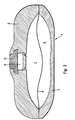
- FIG. 2 shows a vertical section through a schematically illustrated implantable infusion pump according to the invention.
- the infusion pump 1 is a disk-shaped, rotationally symmetrical body made of hard plastic with a Pump chamber formed by a lower chamber part 2 and an upper chamber part 3 is formed and by the flexible gas-impermeable partition 6 in two subchambers 7 and 8 is separated.
- the first subchamber 7 serves as a medicament store and the second sub-chamber 8 serves as a pressure chamber for receiving the 1,1,1,4,4,4-hexafluorobutane used as blowing agent.
- the refill opening 12 is tightly covered by a pierceable central septum 13 and instructs the central septum 13 a refill room with a fixed plate as a needle stop and passage openings to the medicament store 7.
- the flexible gas impermeable partition 6 is a commonly used one flexible membrane.
- the foils of the aluminum composite foil are by means of a polyurethane adhesive glued together.
- the foils a) and b) are only along the edge area of the entire circumference connected to each other and the aluminum composite film.
- the partition 6 is with its outer edge region along its circumference between the edge regions of the upper chamber part 3 and the lower chamber part 2 pinched or pressed.
- the 1,1,1,4,4,4-hexafluorobutane used as the blowing agent was thus into the Pressure chamber brought that one through the sealing surface in the edge area Introduced microcapillary, removed the air from the pressure chamber and through the Microcapillary filled the propellant in the pressure chamber.
- the filled in The amount was about 2 ml.
- the internal volume of the pressure chamber 8 is approximately 40 ml, the medicament store 7 can hold about 30 ml of the medical solution.
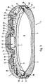
- Figure 3 is a vertical section through a specially designed infusion pump dosed delivery of drugs into the human body.
- the infusion pump 1 is a disk-shaped, rotationally symmetrical body Made of polysulfone, which has a housing that consists of a bowl-shaped chamber lower part 2, a bowl-shaped with opposite curvature Chamber upper part 3, a union part 4 and a septa holder 5 assembled is.
- the interior is by a curved partition 6 and also curved aluminum composite film P in a first sub-chamber, which as Medicament storage 7 is used, and a second sub-chamber, which acts as a pressure chamber 8 to accommodate the 1,1,1,4,4,4-hexafluorobutane used as blowing agent serves, shared.
- the pressure chamber 8 is by edge welding or gluing the partition 6 and the aluminum composite film P is formed pill-shaped.
- An annular groove is formed on the upper inner edge region of the lower chamber part 2, into which a peripheral associated edge 10 of the in a snap connection Chamber upper part 3 together with an O-ring 11 and an edge 36 that from the partition 6 and the aluminum composite film P is formed, locked and is kept tight.
- a refill opening 12 is through a disc-shaped and pierceable Central septum 13 tightly covered, the refill opening 12 being a refill space under the central septum 13 with a fixed plate as a needle stop and Has passage openings to the drug store 7.
- a concentric annular chamber 14 molded in, which is tightly covered by a ring septum 15.
- annular chamber 14 and the refill opening 12 Between the annular chamber 14 and the refill opening 12 is a concentric one Annular groove 16 formed, one on each of the inner and outer side wall circumferential locking groove 17, 18 is attached.
- the ring-shaped septa holder 5 engages with its inner edge the edge of the disc-shaped central septum 13 and with its outer edge the inner edge of the ring septum 15.
- the septa holder 5 engages with ring webs 19, 20 lying next to one another into the annular groove 16, the locking lugs 21, 22 on the annular webs 19, 20 in engage the locking grooves 17, 18.
- the outer edge of the ring septum 15 is in a step-like arrangement covered by a correspondingly shaped edge area of the throwing part 4 and tightly jammed against the upper chamber part 3. To do this is in this border area of the coupling part 4 a snap connection between the coupling part 4 and the upper chamber part 3 is provided, which from a circumferential locking groove 23 on Cover part 4 and a circumferential locking lug 24 on the upper chamber part 3.
- annular space 28 for receiving a Outlet reducing device 29 (here schematically as a section through a capillary shown) and an outlet catheter 30 is formed.
- connection 31 formed from the annular groove 9, the edge 10 and the O-ring 11, the connection 32, formed from the locking groove 23 and the locking lug 24 as well make the connection 33, consisting of the locking groove 18 and the locking lugs 22 Main connections are those that occur under normal operational loads Mainly support internal pressure loads.
- connection 34 consisting of the annular groove 25, the locking lug 26 and the O-ring 27, and the connection 35, consisting of the locking groove 17 and the locking lugs 21, are secondary connections that occur during normal operational load have no or only a small support function. Only when there is a pressure increase above normal operating pressure, especially if the Main connections 31, 32, 33 take over the secondary connections 34, 35 Support function.
- the main connections 31, 32, 33 are in constant engagement and provide the integrity of the implanted infusion pump under normal conditions.
- the secondary connections 34, 35 increasingly engage.
- the voltages are derived from the main connections 31, 32, 33 and split up main and secondary connections.
- the connection task becomes taken from the secondary connection 34.
- the secondary connection 34 is able to Ensure the integrity of the infusion pump to the outside. Is essential that the lower part fails in the upper web area, but not in the lower area, what can be ensured constructively.
- the pill-shaped pressure chamber 8 thus formed has an internal volume of approximately 40 ml and contains about 2 ml of the blowing agent.
- the drug store can Take up about 30 ml of the medical solution.
- This specially designed Infusion pump allows up to a maximum of 120 fillings with the medical Solution and funding rates per day of e.g. 0.7, 1.0, 1.4 or 2 ml of medical Solution.
Landscapes
- Health & Medical Sciences (AREA)
- Hematology (AREA)
- Engineering & Computer Science (AREA)
- Anesthesiology (AREA)
- Biomedical Technology (AREA)
- Heart & Thoracic Surgery (AREA)
- Vascular Medicine (AREA)
- Life Sciences & Earth Sciences (AREA)
- Animal Behavior & Ethology (AREA)
- General Health & Medical Sciences (AREA)
- Public Health (AREA)
- Veterinary Medicine (AREA)
- Infusion, Injection, And Reservoir Apparatuses (AREA)
- Media Introduction/Drainage Providing Device (AREA)
Description
Claims (2)
- Implantierbare Infusionspumpe (1) zur dosierten Abgabe von Medikamenten in den menschlichen Körper, mit einer Pumpenkammer, die durch ein Kammerunterteil (2) und ein damit verbundenes Kammeroberteil (3) gebildet ist, wobeidadurch gekennzeichnet,a) die Pumpenkammer durch eine gasundurchlässige flexible Trennwand (6) in zwei Teilkammern (7, 8) getrennt ist,b) die erste Teilkammer (7) vom Kammeroberteil (3) und der flexiblen Trennwand (6) begrenzt ist und als Speicher für medizinische Lösungen (7) ausgebildet ist, das Kammeroberteil (3) eine Nachfüllöffnung (12) aufweist, die durch wenigstens ein durchstechbares Septum (13) abgedichtet ist, und der Speicher (7) für medizinische Lösungen über eine Auslaßöffnung und gegebenenfalls eine Auslaßreduziereinrichtung (29) mit einem Auslaßkatheter (30) verbunden ist, undc) die zweite Teilkammer vom Kammerunterteil (2) und der flexiblen Trennwand (6) begrenzt ist und als Druckkammer (8) zur Aufnahme eines Treibmittels aus halogeniertem Kohlenwasserstoff ausgebildet ist,
daß das Treibmittel Hexafluorbutan ist. - Infusionspumpe nach Patentanspruch 1, dadurch gekennzeichnet, daß das Treibmittel 1,1,1,4,4,4-Hexafluorbutan ist.
Applications Claiming Priority (2)
| Application Number | Priority Date | Filing Date | Title |
|---|---|---|---|
| DE19509632A DE19509632C1 (de) | 1995-03-17 | 1995-03-17 | Implantierbare Infusionspumpe |
| DE19509632 | 1995-03-17 |
Publications (2)
| Publication Number | Publication Date |
|---|---|
| EP0732112A1 EP0732112A1 (de) | 1996-09-18 |
| EP0732112B1 true EP0732112B1 (de) | 2000-02-23 |
Family
ID=7756902
Family Applications (1)
| Application Number | Title | Priority Date | Filing Date |
|---|---|---|---|
| EP96103911A Expired - Lifetime EP0732112B1 (de) | 1995-03-17 | 1996-03-13 | Implantierbare Infusionspumpe |
Country Status (5)
| Country | Link |
|---|---|
| US (1) | US5722957A (de) |
| EP (1) | EP0732112B1 (de) |
| JP (1) | JPH08266620A (de) |
| DE (2) | DE19509632C1 (de) |
| ES (1) | ES2145336T3 (de) |
Families Citing this family (58)
| Publication number | Priority date | Publication date | Assignee | Title |
|---|---|---|---|---|
| DE19509634C1 (de) * | 1995-03-17 | 1996-03-28 | Fresenius Ag | Implantierbare Infusionspumpe |
| US5957890A (en) * | 1997-06-09 | 1999-09-28 | Minimed Inc. | Constant flow medication infusion pump |
| US6183461B1 (en) | 1998-03-11 | 2001-02-06 | Situs Corporation | Method for delivering a medication |
| US6283943B1 (en) * | 1999-02-19 | 2001-09-04 | Minimed Inc. | Negative pressure pump |
| US6280416B1 (en) * | 1999-02-19 | 2001-08-28 | Minimed Inc. | Constant flow medication infusion pump |
| US6139535A (en) * | 1999-05-27 | 2000-10-31 | Situs Corporation | Method and apparatus for placement and activation of a medical device within a body cavity |
| US6589205B1 (en) | 1999-12-17 | 2003-07-08 | Advanced Bionica Corporation | Externally-controllable constant-flow medication delivery system |
| US6764472B1 (en) | 2000-01-11 | 2004-07-20 | Bard Access Systems, Inc. | Implantable refillable infusion device |
| US7776029B2 (en) * | 2001-01-30 | 2010-08-17 | The Alfred E. Mann Foundation For Scientific Research | Microminiature infusion pump |
| US20030017066A1 (en) * | 2001-07-19 | 2003-01-23 | Baxter International Inc. | Apparatus, flexible bag and method for dispensing |
| US6769231B2 (en) | 2001-07-19 | 2004-08-03 | Baxter International, Inc. | Apparatus, method and flexible bag for use in manufacturing |
| US6905314B2 (en) | 2001-10-16 | 2005-06-14 | Baxter International Inc. | Pump having flexible liner and compounding apparatus having such a pump |
| US20040144799A1 (en) * | 2003-01-24 | 2004-07-29 | Baxter International Inc. | Liquid dispenser and flexible bag therefor |
| US7007824B2 (en) * | 2003-01-24 | 2006-03-07 | Baxter International Inc. | Liquid dispenser and flexible bag therefor |
| AU2004251810B2 (en) | 2003-06-27 | 2010-03-04 | Novo Nordisk A/S | High moisture barrier container for medical liquid compositions |
| US20050011908A1 (en) * | 2003-07-16 | 2005-01-20 | Baxter International, Inc. | Dispenser and pressure/vacuum converting machine |
| CN1898087A (zh) | 2003-12-22 | 2007-01-17 | 诺沃挪第克公司 | 用于储存药物液体的透明、柔性、不可渗透的塑料容器 |
| JP4722654B2 (ja) * | 2004-12-20 | 2011-07-13 | ルネサスエレクトロニクス株式会社 | オシレータ及びこれを用いたチャージポンプ回路 |
| US7637892B2 (en) * | 2005-05-10 | 2009-12-29 | Palyon Medical (Bvi) Limited | Variable flow infusion pump system |
| US8915893B2 (en) | 2005-05-10 | 2014-12-23 | Palyon Medical (Bvi) Limited | Variable flow infusion pump system |
| US8211060B2 (en) | 2005-05-10 | 2012-07-03 | Palyon Medical (Bvi) Limited | Reduced size implantable pump |
| US8114055B2 (en) | 2005-05-10 | 2012-02-14 | Palyon Medical (Bvi) Limited | Implantable pump with infinitely variable resistor |
| US8034029B2 (en) | 2005-05-25 | 2011-10-11 | Palyon Medical (Bvi) Limited | Multi-reservoir implantable pump with patient controlled actuation |
| EP1738896A1 (de) * | 2005-06-28 | 2007-01-03 | Novo Nordisk A/S | Mehrschichtfilm mit Septumschicht |
| JP5058163B2 (ja) * | 2005-07-22 | 2012-10-24 | メドトロニック,インコーポレイテッド | 薬剤を吐出する小型ポンプ |
| WO2007077255A2 (en) * | 2006-01-06 | 2007-07-12 | Novo Nordisk A/S | A medication delivery device applying a collapsible reservoir |
| US7708730B2 (en) | 2006-01-30 | 2010-05-04 | Palyon Medical (Bvi) Limited | Template system for multi-reservoir implantable pump |
| US9023063B2 (en) | 2008-04-17 | 2015-05-05 | Apollo Endosurgery, Inc. | Implantable access port device having a safety cap |
| EP2300095B1 (de) | 2008-04-17 | 2015-03-11 | Apollo Endosurgery, Inc. | Implantierbare Shunt-Vorrichtung und Befestigungssystem |
| CN102202706A (zh) * | 2008-05-08 | 2011-09-28 | 迷你泵有限责任公司 | 可植入药物传送装置与用于填充该装置的设备和方法 |
| US8337488B2 (en) * | 2008-09-22 | 2012-12-25 | Incube Labs, Llc | Diaphragm drug pump |
| US8105269B2 (en) * | 2008-10-24 | 2012-01-31 | Baxter International Inc. | In situ tubing measurements for infusion pumps |
| US8137083B2 (en) | 2009-03-11 | 2012-03-20 | Baxter International Inc. | Infusion pump actuators, system and method for controlling medical fluid flowrate |
| US8506532B2 (en) * | 2009-08-26 | 2013-08-13 | Allergan, Inc. | System including access port and applicator tool |
| US8708979B2 (en) | 2009-08-26 | 2014-04-29 | Apollo Endosurgery, Inc. | Implantable coupling device |
| US8715158B2 (en) * | 2009-08-26 | 2014-05-06 | Apollo Endosurgery, Inc. | Implantable bottom exit port |
| US8231598B2 (en) | 2009-10-30 | 2012-07-31 | Palyon Medical (Bvi) Limited | Propellant bag improvement |
| US8382447B2 (en) * | 2009-12-31 | 2013-02-26 | Baxter International, Inc. | Shuttle pump with controlled geometry |
| US20110196195A1 (en) * | 2010-02-05 | 2011-08-11 | Allergan, Inc. | Implantable subcutaneous access port |
| US8882728B2 (en) * | 2010-02-10 | 2014-11-11 | Apollo Endosurgery, Inc. | Implantable injection port |
| US20110270021A1 (en) | 2010-04-30 | 2011-11-03 | Allergan, Inc. | Electronically enhanced access port for a fluid filled implant |
| US8992415B2 (en) | 2010-04-30 | 2015-03-31 | Apollo Endosurgery, Inc. | Implantable device to protect tubing from puncture |
| US20110270025A1 (en) | 2010-04-30 | 2011-11-03 | Allergan, Inc. | Remotely powered remotely adjustable gastric band system |
| US8567235B2 (en) | 2010-06-29 | 2013-10-29 | Baxter International Inc. | Tube measurement technique using linear actuator and pressure sensor |
| US20120041258A1 (en) | 2010-08-16 | 2012-02-16 | Allergan, Inc. | Implantable access port system |
| US20120065460A1 (en) | 2010-09-14 | 2012-03-15 | Greg Nitka | Implantable access port system |
| US8876771B2 (en) | 2010-11-16 | 2014-11-04 | Palyon Medical (Bvi) Limited | Propellant pillow manufacturing technique |
| US8636693B2 (en) | 2011-04-27 | 2014-01-28 | Palyon Medical Corporation | Propellant pillow |
| US8821373B2 (en) | 2011-05-10 | 2014-09-02 | Apollo Endosurgery, Inc. | Directionless (orientation independent) needle injection port |
| US8801597B2 (en) | 2011-08-25 | 2014-08-12 | Apollo Endosurgery, Inc. | Implantable access port with mesh attachment rivets |
| US9199069B2 (en) | 2011-10-20 | 2015-12-01 | Apollo Endosurgery, Inc. | Implantable injection port |
| US8858421B2 (en) | 2011-11-15 | 2014-10-14 | Apollo Endosurgery, Inc. | Interior needle stick guard stems for tubes |
| US9089395B2 (en) | 2011-11-16 | 2015-07-28 | Appolo Endosurgery, Inc. | Pre-loaded septum for use with an access port |
| US8568360B2 (en) | 2011-12-28 | 2013-10-29 | Palyon Medical (Bvi) Limited | Programmable implantable pump design |
| US8591456B2 (en) | 2011-12-28 | 2013-11-26 | Palyon Medical (Bvi) Limited | Multiple reservoir programmable pump |
| WO2014159866A1 (en) | 2013-03-13 | 2014-10-02 | Palyon Medical Corporation | Dual rate insulin pump |
| RU2633228C1 (ru) * | 2014-04-30 | 2017-10-11 | Кимберли-Кларк Ворлдвайд, Инк. | Картридж для подачи текучей среды в устройство трансдермальной доставки лекарств (варианты) |
| CA3022385A1 (en) * | 2016-04-26 | 2017-11-02 | Saint Louis University | Highly selective adenosine a3 receptor subtype agonsists for the prevention and treatment of neurodegenerative disorders |
Family Cites Families (11)
| Publication number | Priority date | Publication date | Assignee | Title |
|---|---|---|---|---|
| FR2091189A5 (de) * | 1970-05-18 | 1972-01-14 | Regents University Minne | |
| US3951147A (en) * | 1975-04-07 | 1976-04-20 | Metal Bellows Company | Implantable infusate pump |
| US4714462A (en) * | 1986-02-03 | 1987-12-22 | Intermedics Infusaid, Inc. | Positive pressure programmable infusion pump |
| US4784648A (en) * | 1986-09-15 | 1988-11-15 | Applied Biomedical Corporation | Infiltration indicator and alarm |
| DE3735467A1 (de) * | 1987-10-20 | 1989-05-03 | Bayer Ag | Verfahren zur herstellung von fluorierten c(pfeil abwaerts)4(pfeil abwaerts)- bis c(pfeil abwaerts)6(pfeil abwaerts)-kohlenwasserstoffen und neue cyclische fluorierte kohlenwasserstoffe, sowie die verwendung von fluorierten c(pfeil abwaerts)4(pfeil abwaerts)- bis c(pfeil abwaerts)6(pfeil abwaerts)-kohlenwasserstoffen als treibgas und arbeitsfluessigkeit fuer waermepumpensysteme |
| US4931050A (en) * | 1988-04-13 | 1990-06-05 | Shiley Infusaid Inc. | Constant pressure variable flow pump |
| DE3915251A1 (de) * | 1989-05-10 | 1990-11-22 | Annemarie Schloegl Ges M B H | Implantierbare vorrichtung zur dosierten abgabe von medikamenten in den menschlichen koerper |
| US5242406A (en) * | 1990-10-19 | 1993-09-07 | Sil Medics Ltd. | Liquid delivery device particularly useful for delivering drugs |
| DE4038049C2 (de) * | 1990-11-29 | 1994-12-01 | Anschuetz & Co Gmbh | Implantierbare Infusionspumpe |
| US5207645A (en) * | 1991-06-25 | 1993-05-04 | Medication Delivery Devices | Infusion pump, treatment fluid bag therefor, and method for the use thereof |
| US5514103A (en) * | 1994-06-14 | 1996-05-07 | Minimed Inc. | Medication infusion pump with improved pressure reservoir |
-
1995
- 1995-03-17 DE DE19509632A patent/DE19509632C1/de not_active Expired - Lifetime
-
1996
- 1996-03-13 ES ES96103911T patent/ES2145336T3/es not_active Expired - Lifetime
- 1996-03-13 DE DE59604474T patent/DE59604474D1/de not_active Expired - Lifetime
- 1996-03-13 EP EP96103911A patent/EP0732112B1/de not_active Expired - Lifetime
- 1996-03-15 US US08/618,432 patent/US5722957A/en not_active Expired - Lifetime
- 1996-03-18 JP JP8061421A patent/JPH08266620A/ja active Pending
Also Published As
| Publication number | Publication date |
|---|---|
| JPH08266620A (ja) | 1996-10-15 |
| DE19509632C1 (de) | 1996-03-28 |
| EP0732112A1 (de) | 1996-09-18 |
| ES2145336T3 (es) | 2000-07-01 |
| US5722957A (en) | 1998-03-03 |
| DE59604474D1 (de) | 2000-03-30 |
Similar Documents
| Publication | Publication Date | Title |
|---|---|---|
| EP0732112B1 (de) | Implantierbare Infusionspumpe | |
| EP0732113B1 (de) | Implantierbare Infusionspumpe | |
| DE68920049T2 (de) | Implantierbare infusionsvorrichtung. | |
| DE60124671T2 (de) | Implantierbare wiederauffüllbare infusionsvorrichtung | |
| DE4225524C2 (de) | Implantierbare Infusionsvorrichtung | |
| EP0701831B1 (de) | Implantierbare Infusionspumpe | |
| US6471688B1 (en) | Osmotic pump drug delivery systems and methods | |
| DE3872611T2 (de) | ||
| EP0242351B1 (de) | Vorrichtung zur strömungskonstanten Abgabe flüssiger Arzneimittel | |
| DE69839370T2 (de) | Einlass für Medikamenteninfusionspumpe | |
| DE2652026C2 (de) | Gerät zur Infusion von Flüssigkeiten | |
| DE69918545T2 (de) | Infusionssystem mit patientenseitig kontrollierter dosiervorrichtung | |
| DE19510583C1 (de) | Implantierbare Infusionspumpe | |
| EP0742025B1 (de) | Verfahren zum Befüllen einer Pumpenkammer einer gasdruckbetriebenen Medikamentenpumpe | |
| DE60106261T2 (de) | Abgabevorrichtung mit mikronadeln zur transdermalen verabreichung von einer substanz | |
| DE69017004T2 (de) | Einrichtung zur Infusion eines Medikaments unter Drosselung der Nachfüllung der Dosis. | |
| EP0347743B1 (de) | Septum für implantierbare Vorrichtungen zur Abgabe von Wirkstoffen | |
| US6852106B2 (en) | Implantable refillable and ported controlled release drug delivery device | |
| US5085656A (en) | Implantable device for the dosed administration of medicaments to the human body | |
| DE10126393A1 (de) | Medikamentenpumpe mit Verstärkungsrillen | |
| DE60118402T2 (de) | Vorrichtung und verfahren zur befestigung von unterschale und oberschale einer implantierbare medikamentpumpe | |
| DE3751141T2 (de) | Implantierbare Pumpe. | |
| US6464688B1 (en) | Osmotic pump delivery system with flexible drug compartment | |
| DE10125261A1 (de) | Medikamentenpumpe mit bündig zu der äußeren Oberfläche abschließenden Vernähschlaufe | |
| DE3228595A1 (de) | System zur parenteralen verabreichung eines wirkstoffs |
Legal Events
| Date | Code | Title | Description |
|---|---|---|---|
| PUAI | Public reference made under article 153(3) epc to a published international application that has entered the european phase |
Free format text: ORIGINAL CODE: 0009012 |
|
| AK | Designated contracting states |
Kind code of ref document: A1 Designated state(s): DE ES FR GB IT |
|
| 17P | Request for examination filed |
Effective date: 19961001 |
|
| GRAG | Despatch of communication of intention to grant |
Free format text: ORIGINAL CODE: EPIDOS AGRA |
|
| GRAG | Despatch of communication of intention to grant |
Free format text: ORIGINAL CODE: EPIDOS AGRA |
|
| GRAH | Despatch of communication of intention to grant a patent |
Free format text: ORIGINAL CODE: EPIDOS IGRA |
|
| 17Q | First examination report despatched |
Effective date: 19990702 |
|
| GRAH | Despatch of communication of intention to grant a patent |
Free format text: ORIGINAL CODE: EPIDOS IGRA |
|
| GRAA | (expected) grant |
Free format text: ORIGINAL CODE: 0009210 |
|
| AK | Designated contracting states |
Kind code of ref document: B1 Designated state(s): DE ES FR GB IT |
|
| GBT | Gb: translation of ep patent filed (gb section 77(6)(a)/1977) |
Effective date: 20000223 |
|
| ITF | It: translation for a ep patent filed | ||
| REF | Corresponds to: |
Ref document number: 59604474 Country of ref document: DE Date of ref document: 20000330 |
|
| ET | Fr: translation filed | ||
| REG | Reference to a national code |
Ref country code: ES Ref legal event code: FG2A Ref document number: 2145336 Country of ref document: ES Kind code of ref document: T3 |
|
| PLBE | No opposition filed within time limit |
Free format text: ORIGINAL CODE: 0009261 |
|
| STAA | Information on the status of an ep patent application or granted ep patent |
Free format text: STATUS: NO OPPOSITION FILED WITHIN TIME LIMIT |
|
| 26N | No opposition filed | ||
| REG | Reference to a national code |
Ref country code: GB Ref legal event code: IF02 |
|
| REG | Reference to a national code |
Ref country code: FR Ref legal event code: TP |
|
| REG | Reference to a national code |
Ref country code: GB Ref legal event code: 732E |
|
| REG | Reference to a national code |
Ref country code: FR Ref legal event code: CD |
|
| REG | Reference to a national code |
Ref country code: FR Ref legal event code: CD |
|
| PGFP | Annual fee paid to national office [announced via postgrant information from national office to epo] |
Ref country code: IT Payment date: 20140318 Year of fee payment: 19 Ref country code: ES Payment date: 20140324 Year of fee payment: 19 Ref country code: FR Payment date: 20140225 Year of fee payment: 19 |
|
| PGFP | Annual fee paid to national office [announced via postgrant information from national office to epo] |
Ref country code: GB Payment date: 20140225 Year of fee payment: 19 |
|
| REG | Reference to a national code |
Ref country code: DE Ref legal event code: R082 Ref document number: 59604474 Country of ref document: DE Representative=s name: MAI, OPPERMANN & PARTNER I. L., DE |
|
| PGFP | Annual fee paid to national office [announced via postgrant information from national office to epo] |
Ref country code: DE Payment date: 20150331 Year of fee payment: 20 |
|
| GBPC | Gb: european patent ceased through non-payment of renewal fee |
Effective date: 20150313 |
|
| PG25 | Lapsed in a contracting state [announced via postgrant information from national office to epo] |
Ref country code: IT Free format text: LAPSE BECAUSE OF NON-PAYMENT OF DUE FEES Effective date: 20150313 |
|
| REG | Reference to a national code |
Ref country code: FR Ref legal event code: ST Effective date: 20151130 |
|
| PG25 | Lapsed in a contracting state [announced via postgrant information from national office to epo] |
Ref country code: GB Free format text: LAPSE BECAUSE OF NON-PAYMENT OF DUE FEES Effective date: 20150313 |
|
| PG25 | Lapsed in a contracting state [announced via postgrant information from national office to epo] |
Ref country code: FR Free format text: LAPSE BECAUSE OF NON-PAYMENT OF DUE FEES Effective date: 20150331 |
|
| REG | Reference to a national code |
Ref country code: DE Ref legal event code: R071 Ref document number: 59604474 Country of ref document: DE |
|
| REG | Reference to a national code |
Ref country code: ES Ref legal event code: FD2A Effective date: 20160427 |
|
| PG25 | Lapsed in a contracting state [announced via postgrant information from national office to epo] |
Ref country code: ES Free format text: LAPSE BECAUSE OF NON-PAYMENT OF DUE FEES Effective date: 20150314 |