EP0731877B1 - Verbrennungsmotor - Google Patents
Verbrennungsmotor Download PDFInfo
- Publication number
- EP0731877B1 EP0731877B1 EP95900652A EP95900652A EP0731877B1 EP 0731877 B1 EP0731877 B1 EP 0731877B1 EP 95900652 A EP95900652 A EP 95900652A EP 95900652 A EP95900652 A EP 95900652A EP 0731877 B1 EP0731877 B1 EP 0731877B1
- Authority
- EP
- European Patent Office
- Prior art keywords
- piston
- cooling oil
- orifice
- annular duct
- feed
- Prior art date
- Legal status (The legal status is an assumption and is not a legal conclusion. Google has not performed a legal analysis and makes no representation as to the accuracy of the status listed.)
- Expired - Lifetime
Links
- 238000002485 combustion reaction Methods 0.000 title claims description 6
- 238000001816 cooling Methods 0.000 claims description 56
- 239000002184 metal Substances 0.000 claims description 3
- 230000002093 peripheral effect Effects 0.000 claims 3
- 230000000694 effects Effects 0.000 description 4
- 238000005553 drilling Methods 0.000 description 1
- 230000017525 heat dissipation Effects 0.000 description 1
- 239000008141 laxative Substances 0.000 description 1
- 230000002475 laxative effect Effects 0.000 description 1
- 239000007921 spray Substances 0.000 description 1
- 230000007704 transition Effects 0.000 description 1
Images
Classifications
-
- F—MECHANICAL ENGINEERING; LIGHTING; HEATING; WEAPONS; BLASTING
- F16—ENGINEERING ELEMENTS AND UNITS; GENERAL MEASURES FOR PRODUCING AND MAINTAINING EFFECTIVE FUNCTIONING OF MACHINES OR INSTALLATIONS; THERMAL INSULATION IN GENERAL
- F16J—PISTONS; CYLINDERS; SEALINGS
- F16J1/00—Pistons; Trunk pistons; Plungers
- F16J1/08—Constructional features providing for lubrication
-
- F—MECHANICAL ENGINEERING; LIGHTING; HEATING; WEAPONS; BLASTING
- F01—MACHINES OR ENGINES IN GENERAL; ENGINE PLANTS IN GENERAL; STEAM ENGINES
- F01P—COOLING OF MACHINES OR ENGINES IN GENERAL; COOLING OF INTERNAL-COMBUSTION ENGINES
- F01P3/00—Liquid cooling
- F01P3/06—Arrangements for cooling pistons
- F01P3/08—Cooling of piston exterior only, e.g. by jets
-
- F—MECHANICAL ENGINEERING; LIGHTING; HEATING; WEAPONS; BLASTING
- F02—COMBUSTION ENGINES; HOT-GAS OR COMBUSTION-PRODUCT ENGINE PLANTS
- F02F—CYLINDERS, PISTONS OR CASINGS, FOR COMBUSTION ENGINES; ARRANGEMENTS OF SEALINGS IN COMBUSTION ENGINES
- F02F3/00—Pistons
- F02F3/16—Pistons having cooling means
- F02F3/20—Pistons having cooling means the means being a fluid flowing through or along piston
- F02F3/22—Pistons having cooling means the means being a fluid flowing through or along piston the fluid being liquid
-
- F—MECHANICAL ENGINEERING; LIGHTING; HEATING; WEAPONS; BLASTING
- F02—COMBUSTION ENGINES; HOT-GAS OR COMBUSTION-PRODUCT ENGINE PLANTS
- F02F—CYLINDERS, PISTONS OR CASINGS, FOR COMBUSTION ENGINES; ARRANGEMENTS OF SEALINGS IN COMBUSTION ENGINES
- F02F3/00—Pistons
Definitions
- the invention relates to an internal combustion engine with at least a cooling oil syringe arranged in the motor housing and at least one reciprocating piston made in particular of light metal according to the preamble of claim 1.
- the inlet and outlet openings are each in Circumferential direction of the annular channel elongated openings. These elongated openings are said to cover the entire between the adjacent hubs of the piston fill in to be as long as possible.
- the elongated The shape of the inlet opening should serve to inject the Cooling oil jet during the stroke movement of the piston hit different areas of the piston head to be able to leave.
- the cooling oil is replaced by a Cooling oil syringe from the crank chamber at an angle to the piston head sprayed.
- a disadvantage of such a piston is that it is because of of the large inlet and outlet openings that relate to pressure and Counter pressure side of the piston over the entire range between the piston hubs, at a high load on the piston not sufficient strength guaranteed. Furthermore, such Execution does not have a good cooling effect due to that in the cooling channel circulating cooling oil can be achieved. Because for a good one The cooling effect is a continuous partial filling of the cooling oil ring channel necessary. Such a partial filling the annular channel space, however, sets a relatively small one Drain opening ahead.
- the invention deals with the Problem with the generic internal combustion engine and drain openings of the cooling oil ring channel of the reciprocating piston to change that on the one hand an optimal cooling effect achieved by the cooling oil circulating in the ring channel and that on the other hand one for a high piston load ensures sufficient strength of the piston is.
- the solution according to the invention makes it possible from an oblique angle most of the injected cooling oil jet into the cooling oil ring channel to be able to introduce.
- the funnel-shaped Execution of the supply opening in the cooling oil ring channel really important.
- oblique cooling oil jets are intentional used in engines with pistons that are not closed Have cooling oil ring channel and where the cooling oil jet directly into the zenith area of the inside of the piston skirt is directed. Due to the oblique alignment of the cooling oil jet hits this due to the stroke movement of the Piston at different locations of the above Zenith area. For pistons without a closed cooling oil ring channel this fact is exploited to by diagonally injected cooling oil the two opposite Hubs of the piston skirt at different stroke positions spray on the piston directly and therefore particularly to be able to cool well. In some cases it is desirable in the same motor housing, i.e. H.
- the length of the feed opening should be in Ring channel direction be as small as possible, so that here between Strength and as large as possible leading into the cooling channel Feed opening a compromise must be found.
- the opening cross-section of the drain opening should be approximately a maximum of one third of the opening cross-sectional area of the feed opening measure up.
- a piston is known from DE-AS 1 191 176, at which the cooling oil channels through holes that are skewed to Piston axis are formed, two each Boreholes in the zenith are interconnected.
- a Cooling oil ring channel as in the subject of the invention not formed by the holes. Through the holes both the stem and the piston head are weakened.
- Cooling oil channels give way due to the height differences in them Course from that of the subject of the invention. A continuous one Partial filling during engine operation and one of them resulting shaker effect with a correspondingly good one Heat dissipation is not expected. The possibility of one optimal positioning of the cooling channels relative to the Areas to be cooled are also severely restricted because only straight cooling channels can be produced by drilling.
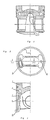
- a light metal piston 1 is in its piston head area provided with a closed cooling oil ring channel 2. This Channel is with a feed opening 3 and a drain opening 4 provided.
- Cooling oil jet 6 For the introduction of cooling oil into the supply opening 3 is one Oil syringe 5 firmly on the motor housing in the upper area of the Engine crankcase arranged. The one leaving the cooling oil syringe Cooling oil jet 6 is aligned with the supply opening 3.
- the cross section of the feed opening goes into the inside of the piston skirt 3 funnel-shaped over.
- This funnel area 7 is designed so that it is steplessly in the radial inner shaft area comes in.
- the inside contour of the piston in a through the opening area of the feed opening 3 Radial plane curved. This gives there is a practically completely surrounding funnel area 7, in which the cooling oil jet can be caught very effectively can.
- the funnel area 7 very effectively into the feed opening 3 introduced.
- the cooling oil syringe is 5 aligned so that the cooling oil jet 6 obliquely runs to the piston axis.
- the oblique course is there such as that used to cool a piston without a closed one Cooling oil ring channel should be designed.
- the cooling oil syringe With one Alignment of the cooling oil syringe prepares this almost completely Collecting the cooling oil jet within the funnel area 7 during all stroke positions of the piston no problems at all. It is rather the case that the cooling oil ring channel during all stroke positions uniform filling volume with a predetermined filling level has, which is the smaller compared to the feed opening 3 Drain opening 4 is crucial.
Landscapes
- Engineering & Computer Science (AREA)
- General Engineering & Computer Science (AREA)
- Chemical & Material Sciences (AREA)
- Combustion & Propulsion (AREA)
- Mechanical Engineering (AREA)
- Physics & Mathematics (AREA)
- Fluid Mechanics (AREA)
- Pistons, Piston Rings, And Cylinders (AREA)
Description
- Fig. 1
- einen Längsschnitt durch einen Kolben,
- Fig. 2
- eine Ansicht des Kolbens von unten,
- Fig. 3
- einen Teil-Schnitt durch einen Kolben nach Linie III-III in Fig. 2.
Claims (2)
- Verbrennungsmotor mit mindestens einer im Motorgehäuse angeordneten Kühlölspritze und mindestens einem Hubkolben aus insbesondere Leichtmetall mit einer Brennraummulde im Kolbenkopf und einem dort vorgesehenen geschlossenen eine Zu- und mindestens eine Ablauföffnung besitzenden Kühlölringkanal, bei dem das Kühlöl durch die fest mit dem Motorgehäuse verbundene Kühlölspritze vom Kurbelraum aus durch den freien Innenraum des Kolbenschaftes hindurch als freier schräg gegenüber der Kolbenachse ausgerichteter Ölstrahl in die Zufuhröffnung des Kühlölringkanales gespritzt wird, wobei im Motorbetrieb eine Teilfüllung des Kühlölringkanals mit Kühlöl vorliegt und die Zufuhröffnung einen in Kolbenumfangsrichtung langgestreckten Öffnungsrand aufweist und diese Öffnung trichterförmig in den Innenwandbereich des Kolbenschaftes ausläuft, gekennzeichnet durch folgende eine hohe Belastbarkeit des Kolbens gewährleistenden Merkmale:a) die in Umfangsrichtung des Kühlölringkanales (2) liegende Länge der Zufuhröffnung (3) ist geringfügig kürzer als es für ein direktes Auffangen des Ölstrahles in allen Hubstellungen des Kolbens notwendig wäre,b) die Zufuhröffnung (3) grenzt direkt an eine von zwei gegenüberliegenden einen Kolbenbolzen aufnehmenden Naben des Kolbens an,c) die Gesamtlänge der Zufuhröffnung (3) beträgt maximal zwei Drittel des Umfangsabstandes zwischen den Naben des Kolbens,d) die Ablauföffnung (4) ist rund und besitzt einen Durchmesser, der etwa der radialen Breite des Kühlölringkanales entspricht.
- Verbrennungsmotor nach Anspruch 1,
dadurch gekennzeichnet,
daß der Strömungsquerschnitt der Zufuhröffnung (3) mindestens das Dreifache des Öffnungsquerschnittes der Ablauföffnung (3) mißt.
Applications Claiming Priority (3)
| Application Number | Priority Date | Filing Date | Title |
|---|---|---|---|
| DE4340891A DE4340891A1 (de) | 1993-12-01 | 1993-12-01 | Hubkolben für Verbrennungsmotoren aus insbesondere Leichtmetall |
| DE4340891 | 1993-12-01 | ||
| PCT/DE1994/001375 WO1995015433A1 (de) | 1993-12-01 | 1994-11-17 | Hubkolben aus insbesondere leichtmetall für verbrennungsmotoren |
Publications (2)
| Publication Number | Publication Date |
|---|---|
| EP0731877A1 EP0731877A1 (de) | 1996-09-18 |
| EP0731877B1 true EP0731877B1 (de) | 1998-10-21 |
Family
ID=6503882
Family Applications (1)
| Application Number | Title | Priority Date | Filing Date |
|---|---|---|---|
| EP95900652A Expired - Lifetime EP0731877B1 (de) | 1993-12-01 | 1994-11-17 | Verbrennungsmotor |
Country Status (5)
| Country | Link |
|---|---|
| US (1) | US5730090A (de) |
| EP (1) | EP0731877B1 (de) |
| BR (1) | BR9408230A (de) |
| DE (2) | DE4340891A1 (de) |
| WO (1) | WO1995015433A1 (de) |
Families Citing this family (25)
| Publication number | Priority date | Publication date | Assignee | Title |
|---|---|---|---|---|
| DE19621894B4 (de) * | 1995-06-08 | 2004-07-15 | Deutz Ag | Brennkraftmaschine mit Kolbenkühlung |
| BR9601862A (pt) | 1996-06-20 | 1999-08-03 | Metal Leve Sa | Pistão para motor de combustão interna |
| DE19703001C2 (de) * | 1997-01-28 | 1998-12-03 | Alcan Gmbh | Flüssigkeitsgekühlter Kolben |
| DE19747746C1 (de) | 1997-10-29 | 1998-11-19 | Alcan Gmbh | Gekühlter Kolben für Verbrennungskraftmaschinen und Verbrennungskraftmaschinen mit derartigen Kolben |
| DE19929102A1 (de) | 1999-06-24 | 2000-12-28 | Ks Kolbenschmidt Gmbh | Kolben für einen Verbrennungsmotor |
| US6250275B1 (en) | 1999-08-16 | 2001-06-26 | Caterpillar Inc. | Internal combustion engine piston pin lubrication |
| US6318243B1 (en) | 1999-08-31 | 2001-11-20 | D. Kent Jones | Two-piece piston assembly |
| CA2403804A1 (en) * | 2000-03-21 | 2001-09-27 | Curagen Corporation | Vegf-modulated genes and methods employing them |
| US6494170B2 (en) | 2000-12-01 | 2002-12-17 | Caterpillar Inc | Two-piece piston assembly with skirt having pin bore oil ducts |
| DE10214830A1 (de) | 2002-04-04 | 2004-01-08 | Mahle Gmbh | Öleinlass für einen mit Kühlkanal versehenen Kolben eines Verbrennungsmotors |
| DE10230746B4 (de) * | 2002-07-09 | 2015-10-01 | Ks Kolbenschmidt Gmbh | Kolben |
| US6990890B2 (en) * | 2002-11-06 | 2006-01-31 | Federal-Mogul World Wide, Inc. | Monobloc piston having open floor |
| DE102004019630A1 (de) * | 2004-04-22 | 2005-11-17 | Wacker Construction Equipment Ag | Ölversorgung für einen Verbrennungsmotor |
| EP1869076A2 (de) * | 2005-03-10 | 2007-12-26 | Genentech, Inc. | Verfahren und zusammensetzungen zur modulation der gefässintegrität |
| FR2896535B1 (fr) * | 2006-01-26 | 2008-05-02 | Vianney Rabhi | Dispositif de refroidissement et de lubrification par projection d'huile pour moteur a rapport volumetrique variable |
| DE102006056011A1 (de) | 2006-11-28 | 2008-05-29 | Ks Kolbenschmidt Gmbh | Kühlkanalvarianten für Kolben |
| CN103437899A (zh) * | 2013-08-02 | 2013-12-11 | 大连滨城活塞制造有限公司 | 具有花瓣形头部结构的活塞裙 |
| DE102013013962A1 (de) * | 2013-08-23 | 2015-02-26 | Mahle International Gmbh | Baueinheit aus einem Kolben und einer Anspritzdüse für einen Verbrennungsmotor |
| US9869268B2 (en) * | 2013-11-07 | 2018-01-16 | Federal-Mogul Llc | Monolithic, galleryless piston and method of construction thereof |
| US10227948B2 (en) | 2015-12-18 | 2019-03-12 | Mahle International Gmbh | Piston for an internal combustion engine |
| USD886155S1 (en) | 2015-12-18 | 2020-06-02 | Mahle International Gmbh | Piston for an internal combustion engine |
| DE102016201628A1 (de) * | 2016-02-03 | 2017-08-03 | Federal-Mogul Nürnberg GmbH | Kolben aus Stahl- oder Grauguss für einen Verbrennungsmotor und Verfahren zur Herstellung eines Kolbens durch Stahl- oder Grauguss |
| US11326549B2 (en) * | 2020-01-21 | 2022-05-10 | Ford Global Technologies, Llc | 218-0266 volcano-shaped inlet of piston oil-cooling gallery |
| DE102020006344A1 (de) | 2020-10-15 | 2022-04-21 | Daimler Ag | Gekühlter Kolben für eine Verbrennungskraftmaschine |
| DE102024124577A1 (de) | 2024-08-28 | 2026-03-05 | Mahle International Gmbh | Kolben für einen Verbrennungsmotor, Verbrennungsmotor mit zumindest einem solchen Kolben |
Family Cites Families (10)
| Publication number | Priority date | Publication date | Assignee | Title |
|---|---|---|---|---|
| DE1191176B (de) * | 1962-09-08 | 1965-04-15 | Mahle Kg | Kolben fuer Brennkraftmaschinen |
| US3189010A (en) * | 1963-11-21 | 1965-06-15 | Continental Aviat & Eng Corp | Piston for internal combustion engine |
| GB1117610A (en) * | 1965-06-29 | 1968-06-19 | John Peter Hindley | Internal combustion engine piston assemblies |
| JPS6329104B2 (de) * | 1979-04-23 | 1988-06-10 | Kyatapiraa Inc | |
| IT1118774B (it) * | 1979-06-12 | 1986-03-03 | Ass Eng Italia | Perfezionamento relativo aglistantuffi nei motori diesel |
| JPS61138816A (ja) * | 1984-12-07 | 1986-06-26 | Toyota Motor Corp | 直噴式内燃機関の燃料蒸発率制御装置 |
| DE3732927A1 (de) * | 1987-09-30 | 1989-04-13 | Mahle Gmbh | Kuehlbarer tauchkolben fuer verbrennungsmotoren |
| DE3832022C1 (de) * | 1988-09-21 | 1989-09-21 | Mahle Gmbh, 7000 Stuttgart, De | |
| JPH02220733A (ja) * | 1989-02-22 | 1990-09-03 | Aisin Seiki Co Ltd | 内燃機関用ピストンの製造方法 |
| JP2520384Y2 (ja) * | 1989-12-29 | 1996-12-18 | 株式会社ユニシアジェックス | 内燃機関用ピストンの冷却装置 |
-
1993
- 1993-12-01 DE DE4340891A patent/DE4340891A1/de not_active Withdrawn
-
1994
- 1994-11-17 EP EP95900652A patent/EP0731877B1/de not_active Expired - Lifetime
- 1994-11-17 BR BR9408230A patent/BR9408230A/pt not_active IP Right Cessation
- 1994-11-17 US US08/647,947 patent/US5730090A/en not_active Expired - Lifetime
- 1994-11-17 WO PCT/DE1994/001375 patent/WO1995015433A1/de not_active Ceased
- 1994-11-17 DE DE59407154T patent/DE59407154D1/de not_active Expired - Lifetime
Also Published As
| Publication number | Publication date |
|---|---|
| DE4340891A1 (de) | 1995-06-08 |
| WO1995015433A1 (de) | 1995-06-08 |
| EP0731877A1 (de) | 1996-09-18 |
| US5730090A (en) | 1998-03-24 |
| DE59407154D1 (de) | 1998-11-26 |
| BR9408230A (pt) | 1997-08-26 |
Similar Documents
| Publication | Publication Date | Title |
|---|---|---|
| WO1995015433A1 (de) | Hubkolben aus insbesondere leichtmetall für verbrennungsmotoren | |
| DE2831566C2 (de) | ||
| DE102006020642A1 (de) | Verfahren zum Betrieb einer Brennkraftmaschine und Brennkraftmaschine für ein solches Verfahren | |
| EP1198667B1 (de) | Flüssigkeitsgekühlter kolben | |
| EP2142323B1 (de) | Giesskern zur bildung eines kühlkanals in einem giesstechnisch hergestellten kolben | |
| DE10214830A1 (de) | Öleinlass für einen mit Kühlkanal versehenen Kolben eines Verbrennungsmotors | |
| AT521514A4 (de) | Zylinderkopf | |
| EP1627993A1 (de) | Reinigungsvorrichtung für eine Abgasturbine | |
| DE19962325A1 (de) | Hubkolbenmaschine | |
| DE3732925C1 (de) | Gekuehlter Tauchkolben fuer Verbrennungsmotoren | |
| EP1231374B1 (de) | Kolben, insbesondere für eine Brennkraftmaschine | |
| EP0263304B1 (de) | Kraftstoffeinspritzpumpe für Brennkraftmaschinen | |
| DE3423551C2 (de) | ||
| DE69710008T2 (de) | Unterteilte Brennkammer für Dieselbrennkraftmaschine | |
| WO2007110055A1 (de) | Kolben für einen verbrennungsmotor | |
| DE19621894B4 (de) | Brennkraftmaschine mit Kolbenkühlung | |
| DE19549221A1 (de) | Brennkraftmaschine mit einem Nockenantrieb | |
| EP1063409B1 (de) | Kolben für einen Verbrennungsmotor | |
| DE1191176B (de) | Kolben fuer Brennkraftmaschinen | |
| DE102020007484A1 (de) | Kolben für eine Verbrennungskraftmaschine | |
| DE10126359B4 (de) | Kolben für einen Verbrennungsmotor | |
| DE3732927C2 (de) | ||
| DE10326054B4 (de) | Vorrichtung zum Betreiben einer Hubkolben-Brennkraftmaschine | |
| DE69702059T2 (de) | Kolben für eine brennkraftmaschine | |
| DE4338571C2 (de) | Kolben für einen Verbrennungsmotor |
Legal Events
| Date | Code | Title | Description |
|---|---|---|---|
| PUAI | Public reference made under article 153(3) epc to a published international application that has entered the european phase |
Free format text: ORIGINAL CODE: 0009012 |
|
| 17P | Request for examination filed |
Effective date: 19960404 |
|
| AK | Designated contracting states |
Kind code of ref document: A1 Designated state(s): DE FR GB IT |
|
| GRAG | Despatch of communication of intention to grant |
Free format text: ORIGINAL CODE: EPIDOS AGRA |
|
| GRAG | Despatch of communication of intention to grant |
Free format text: ORIGINAL CODE: EPIDOS AGRA |
|
| GRAG | Despatch of communication of intention to grant |
Free format text: ORIGINAL CODE: EPIDOS AGRA |
|
| GRAH | Despatch of communication of intention to grant a patent |
Free format text: ORIGINAL CODE: EPIDOS IGRA |
|
| GRAH | Despatch of communication of intention to grant a patent |
Free format text: ORIGINAL CODE: EPIDOS IGRA |
|
| 17Q | First examination report despatched |
Effective date: 19971211 |
|
| GRAA | (expected) grant |
Free format text: ORIGINAL CODE: 0009210 |
|
| AK | Designated contracting states |
Kind code of ref document: B1 Designated state(s): DE FR GB IT |
|
| GBT | Gb: translation of ep patent filed (gb section 77(6)(a)/1977) |
Effective date: 19981022 |
|
| REF | Corresponds to: |
Ref document number: 59407154 Country of ref document: DE Date of ref document: 19981126 |
|
| ET | Fr: translation filed | ||
| PLBE | No opposition filed within time limit |
Free format text: ORIGINAL CODE: 0009261 |
|
| STAA | Information on the status of an ep patent application or granted ep patent |
Free format text: STATUS: NO OPPOSITION FILED WITHIN TIME LIMIT |
|
| 26N | No opposition filed | ||
| REG | Reference to a national code |
Ref country code: GB Ref legal event code: IF02 |
|
| PGFP | Annual fee paid to national office [announced via postgrant information from national office to epo] |
Ref country code: GB Payment date: 20131120 Year of fee payment: 20 Ref country code: DE Payment date: 20131122 Year of fee payment: 20 |
|
| PGFP | Annual fee paid to national office [announced via postgrant information from national office to epo] |
Ref country code: IT Payment date: 20131121 Year of fee payment: 20 Ref country code: FR Payment date: 20131118 Year of fee payment: 20 |
|
| REG | Reference to a national code |
Ref country code: DE Ref legal event code: R071 Ref document number: 59407154 Country of ref document: DE |
|
| REG | Reference to a national code |
Ref country code: GB Ref legal event code: PE20 Expiry date: 20141116 |
|
| PG25 | Lapsed in a contracting state [announced via postgrant information from national office to epo] |
Ref country code: GB Free format text: LAPSE BECAUSE OF EXPIRATION OF PROTECTION Effective date: 20141116 |