EP0729656B1 - Überbrückungssteckverbinder - Google Patents
Überbrückungssteckverbinder Download PDFInfo
- Publication number
- EP0729656B1 EP0729656B1 EP95902613A EP95902613A EP0729656B1 EP 0729656 B1 EP0729656 B1 EP 0729656B1 EP 95902613 A EP95902613 A EP 95902613A EP 95902613 A EP95902613 A EP 95902613A EP 0729656 B1 EP0729656 B1 EP 0729656B1
- Authority
- EP
- European Patent Office
- Prior art keywords
- housing
- spring contact
- contact
- cavity
- shunt connector
- Prior art date
- Legal status (The legal status is an assumption and is not a legal conclusion. Google has not performed a legal analysis and makes no representation as to the accuracy of the status listed.)
- Expired - Lifetime
Links
- 230000037431 insertion Effects 0.000 claims description 15
- 238000003780 insertion Methods 0.000 claims description 15
- 239000004020 conductor Substances 0.000 claims description 2
- 239000000463 material Substances 0.000 claims description 2
- 229920003023 plastic Polymers 0.000 claims description 2
- 239000004033 plastic Substances 0.000 claims description 2
- 230000005611 electricity Effects 0.000 description 3
- 238000004519 manufacturing process Methods 0.000 description 2
- 229910000906 Bronze Inorganic materials 0.000 description 1
- OAICVXFJPJFONN-UHFFFAOYSA-N Phosphorus Chemical compound [P] OAICVXFJPJFONN-UHFFFAOYSA-N 0.000 description 1
- DMFGNRRURHSENX-UHFFFAOYSA-N beryllium copper Chemical compound [Be].[Cu] DMFGNRRURHSENX-UHFFFAOYSA-N 0.000 description 1
- 239000010974 bronze Substances 0.000 description 1
- KUNSUQLRTQLHQQ-UHFFFAOYSA-N copper tin Chemical compound [Cu].[Sn] KUNSUQLRTQLHQQ-UHFFFAOYSA-N 0.000 description 1
- 239000000523 sample Substances 0.000 description 1
- 229910001220 stainless steel Inorganic materials 0.000 description 1
- 239000010935 stainless steel Substances 0.000 description 1
Images
Classifications
-
- H—ELECTRICITY
- H01—ELECTRIC ELEMENTS
- H01R—ELECTRICALLY-CONDUCTIVE CONNECTIONS; STRUCTURAL ASSOCIATIONS OF A PLURALITY OF MUTUALLY-INSULATED ELECTRICAL CONNECTING ELEMENTS; COUPLING DEVICES; CURRENT COLLECTORS
- H01R31/00—Coupling parts supported only by co-operation with counterpart
- H01R31/08—Short-circuiting members for bridging contacts in a counterpart
-
- H—ELECTRICITY
- H05—ELECTRIC TECHNIQUES NOT OTHERWISE PROVIDED FOR
- H05K—PRINTED CIRCUITS; CASINGS OR CONSTRUCTIONAL DETAILS OF ELECTRIC APPARATUS; MANUFACTURE OF ASSEMBLAGES OF ELECTRICAL COMPONENTS
- H05K3/00—Apparatus or processes for manufacturing printed circuits
- H05K3/22—Secondary treatment of printed circuits
- H05K3/222—Completing of printed circuits by adding non-printed jumper connections
Definitions
- the present invention relates generally to electrical connectors. More particularly, this invention relates to a jumper or shunt connector for providing an electrical connection between two terminal pins inserted into the shunt.
- Shunt or jumper connectors are known in the art which provide an electrical connection between two adjacent electrically conductive terminal pins inserted into the device. Upon insertion of the terminal pins into the shunt device, electrical connection is established when the pins contact a conducting member or the like disposed within the device such that the flow of electricity between the pins is shorted in a known manner.
- the shunt device may be used to provide a permanent electrical connection to a printed circuit board or the like or may be used to provide only a temporary connection depending on the circuit requirements.
- the trend in the connector industry is to provide a shunt connector comprising an insulating housing having a plurality of conductive contacting elements disposed therein.
- the insulating housing provides protection from the environment for the contacting elements such that the risk of short-circuiting is minimized.
- Schwab discloses a modular electrical shunt comprising an insulating housing which is formed of two halves joined together such that a cavity is formed within the housing.
- a convex bowed dual-beam leaf spring is disposed in the cavity such that the convex body portion of the leaf spring extends longitudinally outward into the cavity from opposite edges of the leaf spring. The edges of the leaf spring are disposed against the housing for retaining the spring in the cavity.
- the terminal pins are inserted into grooves in the housing along an axis which is parallel to the longitudinal axis of the leaf springs such that the pins engage contacting surfaces at the outermost bowed portion of the leaf spring for creating a short between the terminal pins.
- shunts or jumpers are provided in Walkup, U.S. Pat. No. 4,392,702 and Crowley, U.S. Pat. No. 4,482,198.
- These devices also comprise a housing structure for electrically connecting an array of adjacent terminal pins to a plurality of contacting elements disposed within the housing. Similar to that of Schwab, convex bowed contacting elements are disposed in the device such that the pins are inserted in a direction which is parallel to the longitudinal axis of the contacting element and the pins make contact only at the apex of the outermost bowed portion of the convexly curved pin-gripping portions.
- a shunt connector comprising a spring contact which is arranged substantially transverse to the insertion axis is disclosed in US-A-4 470 652.
- a shunt connector which is comprised of a minimal number of parts and may be manufactured and assembled easily and less costly and which provides a spring contacting element which ensures that a proper electrical connection is made between the terminal pins inserted into the device.
- the present invention provides a shunt or jumper which satisfies this need.
- the shunt connector according to claim 1 provides an electrical connection between terminal pins inserted into the device so as to short the flow of electricity between the pins. Accordingly, such a device may be used to provide a permanent or temporary short of terminal pins connected to a printed circuit assembly or the like and may be easily and cost effectively configured to the requirements of the circuit board user.
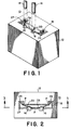
- Fig. 1 depicts a shunt connector 10 in accordance with the present invention.
- Housing 12 receives two adjacent electrically conductive terminal pins 14 inserted into longitudinal bores 16 formed in the housing 12.
- housing 12 comprises an electrically insulating plastic material.
- a portion of each of the longitudinal bores 16 is formed at cavity 18 formed in the housing 12.
- Electrically conducting spring contact 20 is disposed in cavity 18.
- shoulder 22 forms the bottom of cavity 18 such that when the spring contact 20 is inserted into cavity 18 it comes to rest on shoulder 22.
- spring contact 20 has a pair of edges 24 and a body 26 extending between edges 24.
- Spring contact 20 is manufactured as a bowed piece of conducting material, such as beryllium copper, stainless steel, or phosphor bronze.
- Spring contact 20 is a resilient member such that when it is inserted into cavity 18 in housing 12 the spring becomes slightly compressed inside of the cavity.
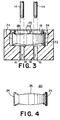
- the body 26 of the spring contact remains bowed along its longitudinal axis and extends outward into cavity 18 as shown in Fig. 2.
- Edges 27 of the housing 12 in the area where the cavity 18 and longitudinal bores 16 are formed are chamfered to guide the spring contact 20 into position during insertion into the cavity 18.
- spring contact 20 Upon insertion of spring contact 20 into cavity 18, the resiliency of the spring contact causes it to be biased against the portion of housing 12 which forms the walls of cavity 18. As shown in Fig. 2, in the embodiment shown spring contact 20 makes contact with housing 12 at least three points p such that the spring contact is held securely in housing 12. Spring contact 20 is inserted into the cavity and is secured under step portion 28 formed in the housing for retaining the spring contact in the cavity. Step portion 28 prevents the spring contact from being inadvertently withdrawn from the cavity under the force of friction between the spring contact and the terminal pins when the pins are taken out of the shunt connector.
- terminal pins 14 are inserted into housing 12 along the longitudinal axis of longitudinal bores 16.
- the axis corresponding to the longitudinal axis of the longitudinal bores is referred to herein as the insertion axis such that the pins 14 are inserted along the insertion axis.
- spring contact 20 is disposed in cavity 18 such that the longitudinal axis of the spring contact is substantially transverse to the insertion axis of the terminal pins 14.
- body 26 of spring contact extends into cavity 18 and substantially breaks the plane which includes the insertion axis of the terminal pins.
- the apex of the bowed portion of spring contact 20 at the corresponding point p is biased toward the housing and the ends of the spring contact are slidably engaged upon the housing in the location of the other two points p such that the spring contact remains in contact with two points on the housing.
- Spring contact 20 establishes an electrical connection between terminal pins 14 so as to short the flow of electricity between the pins.
- Spring contact 20 is biased against pins 14 such that both pins contact body 26 and the pins are electrically connected. Since the convex bowed body 26 extends into cavity 18 in such a manner that the resilient spring is biased against the terminal pins, if the pins are not substantially aligned in parallel the pins will still make contact with body 26.
- longitudinal bores 16 are shown as extending throughout the entire length of housing 12.
- probes may be inserted into the longitudinal bores from the bottom surface of the housing in order to determine if proper electrical connection is established between the terminal pins inserted into the housing.
- the present invention is not intended to be limited in this manner and it is only necessary that the longitudinal bores extend into the housing far enough such that the pins contact the spring contact disposed in the housing.
- the present invention provides a low cost shunt connector which is easily manufactured with a minimum number of parts and which provides a temporary or permanent short for a pair of adjacent terminal pins which are inserted into the connector.
- a spring contacting element is simply inserted into and secured in a cavity in the connector housing such that a reliable electrical connection is formed between the terminal pins regardless of any misalignment of the terminal pins.
Landscapes
- Coupling Device And Connection With Printed Circuit (AREA)
- Details Of Connecting Devices For Male And Female Coupling (AREA)
- Connector Housings Or Holding Contact Members (AREA)
Claims (11)
- Überbrückungsverbinder (10), umfassend:ein Gehäuse (12), wobei das Gehäuse einen Hohlraum (18) sowie Stiftaufnahmemittel mit einer Einsetzachse aufweist, wobei die Stiftaufnahmemittel dazu dienen, ein Paar von benachbarten Anschlußstiften (1 4) aufzunehmen, die in das Gehäuse (12) parallel zu der Einsetzachse eingesetzt werden; und einen Federkontakt (20), der von einem leitfähigen Material gebildet ist und in dem Hohlraum (18) angeordnet ist, wobei der Federkontakt eine Längsachse aufweist, wobei der Federkontakt (20) in dem Hohlraum (18) derart angeordnet und gehalten ist, daß die Längsachse im wesentlichen quer zu der Einsetzachse ist und der Federkontakt in einer Richtung gekrümmt gehalten wird, die quer zu der Einsetzachse ist, um einen einfachen bogenförmigen Abschnitt (26) bereitzustellen, der an einem mittleren Bereich des Federkontakts angeordnet ist, wobei der bogenförmige Abschnitt (26) gegen die Anschlußstifte vorbelastet ist, wenn die Stifte (14) in das Gehäuse eingesetzt sind, wobei die Anschlußstifte (14) in das Gehäuse (12) im wesentlichen quer zu der Längsachse des Federkontakts (20) eingesetzt werden, dadurch gekennzeichnet, daß der Federkontakt (20) ein Blattfederkontakt ist und dadurch, daß beide Anschlußstifte (14) in Eingriff mit dem mittleren Bereich des bogenförmigen Abschnitts (26) des Federkontakts (20) stehen und mit diesem einen elektrischen Kontakt herstellen.
- Überbrückungsverbinder (10) nach Anspruch 1, wobei der Blattfederkontakt (20) einen elastisch konvex gekrümmten Rumpf mit einem Scheitel an der äußersten Stelle des Rumpfs umfaßt, wobei der Blattfederkontakt (20) in dem Hohlraum (18) derart angeordnet ist, daß der Scheitel in einen kontaktierenden Eingriff mit dem Gehäuse (12) vorbelastet ist und der Scheitel hin zu dem Gehäuse (12) vorbelastet bleibt, wenn die Anschlußstifte (14) in das Gehäuse (12) eingesetzt werden.
- Überbrückungsverbinder nach Anspruch 1 oder 2, wobei die Stiftaufnahmemittel ein Paar von Längsbohrungen (16) umfassen.
- Überbrückungsverbinder nach Anspruch 3, wobei ein Abschnitt jeder Bohrung (16) an dem Hohlraum (18) ausgebildet ist.
- Überbrückungsverbinder nach Anspruch 3 oder 4, wobei die Längsbohrungen sich durch das ganze Gehäuse erstrecken.
- Überbrückungsverbinder nach einem der Ansprüche 1 bis 5, wobei der Federkontakt (20) einen Kontakt mit dem Gehäuse wenigstens an drei Stellen an dem Gehäuse herstellt.
- Überbrückungsverbinder nach einem der Ansprüche 1 bis 6, wobei das Gehäuse ferner einen Stufenabschnitt (28) umfaßt, der zum Halten des Federkontakts (20) in dem Hohlraum in den Hohlraum (18) vorsteht.
- Überbrückungsverbinder nach einem der Ansprüche 1 bis 7, wobei das Gehäuse (12) aus einem isolierenden Kunststoffmaterial gebildet ist.
- Überbrückungsverbinder nach Anspruch 2 oder einem der Ansprüche 3 bis 8, sofern auf Anspruch 2 rückbezogen, wobei die Enden (24) des Rumpfs gleitfähig im Eingriff an dem Gehäuse während des Einsetzens der Anschlußstifte in das Gehäuse stehen und der Federkontakt in Kontakt mit zwei Stellen an dem Gehäuse bleibt, wenn die Kontaktstifte in das Gehäuse eingesetzt werden.
- Überbrückungsverbinder nach einem der Ansprüche 1 bis 10, wobei das Gehäuse (12) und der Federkontakt (20) derart ausgebildet sind, daß die Anschlußstifte eine konvexe Seite des bogenförmigen Abschnitts oder gekrümmten Rumpfs der Kontaktfeder elektrisch kontaktieren.
- Überbrückungsverbinder nach einem der Ansprüche 1 bis 11, wobei das Gehäuse (12) und der Federkontakt derart ausgebildet sind, daß Enden (24) des Federkontakts in Eingriff mit dem Gehäuse an einer konkaven Seite des Federkontakts (20) treten.
Applications Claiming Priority (3)
| Application Number | Priority Date | Filing Date | Title |
|---|---|---|---|
| US153630 | 1993-11-17 | ||
| US08/153,630 US5449301A (en) | 1993-11-17 | 1993-11-17 | Shunt connector |
| PCT/US1994/013348 WO1995014318A1 (en) | 1993-11-17 | 1994-11-16 | Shunt connector |
Publications (3)
| Publication Number | Publication Date |
|---|---|
| EP0729656A1 EP0729656A1 (de) | 1996-09-04 |
| EP0729656A4 EP0729656A4 (de) | 1997-05-07 |
| EP0729656B1 true EP0729656B1 (de) | 2000-05-24 |
Family
ID=22548025
Family Applications (1)
| Application Number | Title | Priority Date | Filing Date |
|---|---|---|---|
| EP95902613A Expired - Lifetime EP0729656B1 (de) | 1993-11-17 | 1994-11-16 | Überbrückungssteckverbinder |
Country Status (7)
| Country | Link |
|---|---|
| US (1) | US5449301A (de) |
| EP (1) | EP0729656B1 (de) |
| JP (1) | JPH09505438A (de) |
| DE (1) | DE69424682T2 (de) |
| SG (1) | SG47893A1 (de) |
| TW (1) | TW323407B (de) |
| WO (1) | WO1995014318A1 (de) |
Families Citing this family (19)
| Publication number | Priority date | Publication date | Assignee | Title |
|---|---|---|---|---|
| DE69502108T2 (de) * | 1994-09-06 | 1998-09-17 | Whitaker Corp | Kugelrasterbuchsegehaüse |
| DE19614199C1 (de) * | 1996-04-10 | 1997-10-23 | Wolf Geraete Gmbh Vertrieb | Arbeitsgerät mit einem batteriebetriebenen Elektromotor |
| US5692916A (en) * | 1996-07-03 | 1997-12-02 | Framatome Connectors Usa Inc. | Shunting switch |
| US5782655A (en) * | 1996-09-16 | 1998-07-21 | Stefaniu; Michael V. | Miniature shunt connector with anti-overstress contact element and method of commoning a pair of adjacent terminal posts |
| DE19639723A1 (de) * | 1996-09-26 | 1998-04-09 | Whitaker Corp | Elektrischer Verbinder mit einem Kurzschlußkontakt und Kurzschlußkontakt |
| US5906508A (en) * | 1996-12-18 | 1999-05-25 | Thomas & Betts Corporation | Electrical disconnect for use with an appliance |
| US6036534A (en) * | 1997-02-26 | 2000-03-14 | 3M Innovative Properties Company | Low profile shunt connector |
| US7686521B2 (en) * | 2003-11-10 | 2010-03-30 | Finisar Corporation | Zero force socket for laser / photodiode alignment |
| US7311548B1 (en) * | 2006-07-10 | 2007-12-25 | International Business Machines Corporation | Jumper installation feedback |
| JP5612831B2 (ja) * | 2009-05-20 | 2014-10-22 | モレックス インコーポレイテドMolex Incorporated | ループコネクタ及び閉回路形成コネクタ |
| CN106618669B (zh) | 2010-04-29 | 2019-11-12 | Dfine有限公司 | 用于治疗椎骨骨折的系统 |
| DE102010039957B4 (de) | 2010-08-30 | 2023-03-23 | Robert Bosch Gmbh | Trennbuchsenanordnungen und Trennadapter mit einer Trägerplatte und einer oder mehreren darin angebrachten Trennbuchsen der Trennbuchsenanordnungen |
| CN109862834B (zh) | 2016-10-27 | 2022-05-24 | Dfine有限公司 | 具有接合剂递送通道的可弯曲的骨凿 |
| WO2018098433A1 (en) | 2016-11-28 | 2018-05-31 | Dfine, Inc. | Tumor ablation devices and related methods |
| US10463380B2 (en) | 2016-12-09 | 2019-11-05 | Dfine, Inc. | Medical devices for treating hard tissues and related methods |
| WO2018129180A1 (en) | 2017-01-06 | 2018-07-12 | Dfine, Inc. | Osteotome with a distal portion for simultaneous advancement and articulation |
| US11510723B2 (en) | 2018-11-08 | 2022-11-29 | Dfine, Inc. | Tumor ablation device and related systems and methods |
| US11986229B2 (en) | 2019-09-18 | 2024-05-21 | Merit Medical Systems, Inc. | Osteotome with inflatable portion and multiwire articulation |
| CN110927424B (zh) * | 2019-12-12 | 2021-09-14 | 河南省计量科学研究院 | 一种冲击电流测量用抗振式直流分流器 |
Family Cites Families (11)
| Publication number | Priority date | Publication date | Assignee | Title |
|---|---|---|---|---|
| US3932013A (en) * | 1974-04-08 | 1976-01-13 | Amp Incorporated | Shunt assembly |
| US4070557A (en) * | 1976-07-26 | 1978-01-24 | Northern Telecom Limited | Apparatus for providing closed loop conditions in vacant module positions |
| NL8003228A (nl) * | 1980-06-03 | 1982-01-04 | Du Pont Nederland | Brugkontakt voor het elektrisch met elkaar verbinden van twee pennen. |
| US4392702A (en) * | 1981-04-02 | 1983-07-12 | Ark-Les Corporation | Shorting jumper |
| US4470651A (en) * | 1982-05-04 | 1984-09-11 | B/K Patent Development, Inc. | Modular electrical shunts for integrated circuit applications |
| US4470652A (en) * | 1982-06-04 | 1984-09-11 | B/K Patent Development, Inc. | Modular electrical shunts for integrated circuit applications |
| US4482198A (en) * | 1982-11-08 | 1984-11-13 | Amp Incorporated | Shunt |
| US4516817A (en) * | 1983-04-25 | 1985-05-14 | Deters Paul M | Electrical jumper assembly |
| US4602834A (en) * | 1985-04-15 | 1986-07-29 | E. I. Dupont De Nemours And Company | Electrical jumper |
| US4883430A (en) * | 1988-06-06 | 1989-11-28 | The Siemon Company | Bridge clip carrier |
| US5169337A (en) * | 1991-09-05 | 1992-12-08 | Amp Incorporated | Electrical shunt |
-
1993
- 1993-11-17 US US08/153,630 patent/US5449301A/en not_active Expired - Fee Related
-
1994
- 1994-11-16 SG SG1996005070A patent/SG47893A1/en unknown
- 1994-11-16 DE DE69424682T patent/DE69424682T2/de not_active Expired - Fee Related
- 1994-11-16 JP JP7514627A patent/JPH09505438A/ja active Pending
- 1994-11-16 WO PCT/US1994/013348 patent/WO1995014318A1/en not_active Ceased
- 1994-11-16 EP EP95902613A patent/EP0729656B1/de not_active Expired - Lifetime
- 1994-11-29 TW TW083111075A patent/TW323407B/zh active
Also Published As
| Publication number | Publication date |
|---|---|
| WO1995014318A1 (en) | 1995-05-26 |
| DE69424682D1 (de) | 2000-06-29 |
| US5449301A (en) | 1995-09-12 |
| SG47893A1 (en) | 1998-04-17 |
| JPH09505438A (ja) | 1997-05-27 |
| EP0729656A4 (de) | 1997-05-07 |
| TW323407B (de) | 1997-12-21 |
| DE69424682T2 (de) | 2000-09-07 |
| EP0729656A1 (de) | 1996-09-04 |
Similar Documents
| Publication | Publication Date | Title |
|---|---|---|
| US5449301A (en) | Shunt connector | |
| JP2648841B2 (ja) | 回路盤用縁端接続器 | |
| US4023879A (en) | Adjustable electrical connector with replaceable contact sub-assembly and variable strain relief | |
| US7021957B2 (en) | Woven multiple-contact connector | |
| US4575172A (en) | Low insertion force electrical connector with stress controlled contacts | |
| US5308249A (en) | Backplane connector utilizing flexible film circuitry | |
| EP0561642B1 (de) | Elektrischer Verbinder | |
| US4464007A (en) | Pin terminal mounting system | |
| WO2009064528A1 (en) | Electrical connector mating guide | |
| EP1058352B1 (de) | Elektrischer Verbinder | |
| EP0158413B1 (de) | Elektrischer Stecker mit geringer notwendiger Einsteckkraft und mit beanspruchungsüberwachten Kontakten | |
| US6039590A (en) | Electrical connector with relatively movable two-part housing | |
| USRE34084E (en) | Vertical action contact spring | |
| US5286215A (en) | Make-before-break PC board edge connector | |
| EP0475846B1 (de) | Isolierter Stecker für elektrische Verbinder und Verbinder mit so einem Stecker | |
| WO1994027344A1 (en) | High-density connector | |
| EP0068656B1 (de) | Elektrischer Anschlusskontakt mit Hohlraumausgleichmittel | |
| US5470243A (en) | Electrical connector with snorting switch | |
| US4815982A (en) | Electrical connector having stress-free contacts | |
| US7402049B2 (en) | Contact for an interposer-type connector array | |
| EP0551082B1 (de) | Leiterplatte mit stützender Randverbinder-Einrichtung, Verfahren für deren Zusammenbau sowie Verbinder zu deren Aufnahme | |
| US6361365B1 (en) | Electrical connector having connected grounding plate and grounding pins | |
| US6227898B1 (en) | Card edge connector with removable rail guide | |
| EP0928047B1 (de) | Elektrischer Steckverbinder für Halbleiterbauelemente | |
| US5224885A (en) | Low profile dual beam contact |
Legal Events
| Date | Code | Title | Description |
|---|---|---|---|
| PUAI | Public reference made under article 153(3) epc to a published international application that has entered the european phase |
Free format text: ORIGINAL CODE: 0009012 |
|
| 17P | Request for examination filed |
Effective date: 19960611 |
|
| AK | Designated contracting states |
Kind code of ref document: A1 Designated state(s): DE FR GB |
|
| A4 | Supplementary search report drawn up and despatched |
Effective date: 19970320 |
|
| AK | Designated contracting states |
Kind code of ref document: A4 Designated state(s): DE FR GB |
|
| RAP1 | Party data changed (applicant data changed or rights of an application transferred) |
Owner name: BERG ELECTRONICS MANUFACTURING B.V. |
|
| 17Q | First examination report despatched |
Effective date: 19980730 |
|
| GRAG | Despatch of communication of intention to grant |
Free format text: ORIGINAL CODE: EPIDOS AGRA |
|
| GRAG | Despatch of communication of intention to grant |
Free format text: ORIGINAL CODE: EPIDOS AGRA |
|
| GRAH | Despatch of communication of intention to grant a patent |
Free format text: ORIGINAL CODE: EPIDOS IGRA |
|
| GRAH | Despatch of communication of intention to grant a patent |
Free format text: ORIGINAL CODE: EPIDOS IGRA |
|
| GRAA | (expected) grant |
Free format text: ORIGINAL CODE: 0009210 |
|
| AK | Designated contracting states |
Kind code of ref document: B1 Designated state(s): DE FR GB |
|
| REF | Corresponds to: |
Ref document number: 69424682 Country of ref document: DE Date of ref document: 20000629 |
|
| ET | Fr: translation filed | ||
| PLBE | No opposition filed within time limit |
Free format text: ORIGINAL CODE: 0009261 |
|
| STAA | Information on the status of an ep patent application or granted ep patent |
Free format text: STATUS: NO OPPOSITION FILED WITHIN TIME LIMIT |
|
| 26N | No opposition filed | ||
| PGFP | Annual fee paid to national office [announced via postgrant information from national office to epo] |
Ref country code: GB Payment date: 20011004 Year of fee payment: 8 |
|
| PGFP | Annual fee paid to national office [announced via postgrant information from national office to epo] |
Ref country code: FR Payment date: 20011105 Year of fee payment: 8 |
|
| PGFP | Annual fee paid to national office [announced via postgrant information from national office to epo] |
Ref country code: DE Payment date: 20011130 Year of fee payment: 8 |
|
| REG | Reference to a national code |
Ref country code: GB Ref legal event code: IF02 |
|
| PG25 | Lapsed in a contracting state [announced via postgrant information from national office to epo] |
Ref country code: GB Free format text: LAPSE BECAUSE OF NON-PAYMENT OF DUE FEES Effective date: 20021116 |
|
| PG25 | Lapsed in a contracting state [announced via postgrant information from national office to epo] |
Ref country code: DE Free format text: LAPSE BECAUSE OF NON-PAYMENT OF DUE FEES Effective date: 20030603 |
|
| GBPC | Gb: european patent ceased through non-payment of renewal fee | ||
| PG25 | Lapsed in a contracting state [announced via postgrant information from national office to epo] |
Ref country code: FR Free format text: LAPSE BECAUSE OF NON-PAYMENT OF DUE FEES Effective date: 20030731 |
|
| REG | Reference to a national code |
Ref country code: FR Ref legal event code: ST |