EP0729318B1 - Einrichtung zur ermittlung der wirkung gepulster magnetfelder auf einen organismus - Google Patents
Einrichtung zur ermittlung der wirkung gepulster magnetfelder auf einen organismus Download PDFInfo
- Publication number
- EP0729318B1 EP0729318B1 EP94929522A EP94929522A EP0729318B1 EP 0729318 B1 EP0729318 B1 EP 0729318B1 EP 94929522 A EP94929522 A EP 94929522A EP 94929522 A EP94929522 A EP 94929522A EP 0729318 B1 EP0729318 B1 EP 0729318B1
- Authority
- EP
- European Patent Office
- Prior art keywords
- accordance
- organism
- signals
- evaluation circuit
- storage medium
- Prior art date
- Legal status (The legal status is an assumption and is not a legal conclusion. Google has not performed a legal analysis and makes no representation as to the accuracy of the status listed.)
- Expired - Lifetime
Links
Images


Classifications
-
- A—HUMAN NECESSITIES
- A61—MEDICAL OR VETERINARY SCIENCE; HYGIENE
- A61B—DIAGNOSIS; SURGERY; IDENTIFICATION
- A61B5/00—Measuring for diagnostic purposes; Identification of persons
- A61B5/41—Detecting, measuring or recording for evaluating the immune or lymphatic systems
- A61B5/414—Evaluating particular organs or parts of the immune or lymphatic systems
- A61B5/415—Evaluating particular organs or parts of the immune or lymphatic systems the glands, e.g. tonsils, adenoids or thymus
-
- A—HUMAN NECESSITIES
- A61—MEDICAL OR VETERINARY SCIENCE; HYGIENE
- A61B—DIAGNOSIS; SURGERY; IDENTIFICATION
- A61B5/00—Measuring for diagnostic purposes; Identification of persons
- A61B5/05—Detecting, measuring or recording for diagnosis by means of electric currents or magnetic fields; Measuring using microwaves or radio waves
-
- A—HUMAN NECESSITIES
- A61—MEDICAL OR VETERINARY SCIENCE; HYGIENE
- A61N—ELECTROTHERAPY; MAGNETOTHERAPY; RADIATION THERAPY; ULTRASOUND THERAPY
- A61N2/00—Magnetotherapy
- A61N2/02—Magnetotherapy using magnetic fields produced by coils, including single turn loops or electromagnets
-
- G—PHYSICS
- G01—MEASURING; TESTING
- G01R—MEASURING ELECTRIC VARIABLES; MEASURING MAGNETIC VARIABLES
- G01R33/00—Arrangements or instruments for measuring magnetic variables
- G01R33/12—Measuring magnetic properties of articles or specimens of solids or fluids
-
- A—HUMAN NECESSITIES
- A61—MEDICAL OR VETERINARY SCIENCE; HYGIENE
- A61B—DIAGNOSIS; SURGERY; IDENTIFICATION
- A61B5/00—Measuring for diagnostic purposes; Identification of persons
- A61B5/72—Signal processing specially adapted for physiological signals or for diagnostic purposes
- A61B5/7235—Details of waveform analysis
- A61B5/7239—Details of waveform analysis using differentiation including higher order derivatives
Definitions
- the invention relates to a device for determining the effect of pulsed primary magnetic fields on an organism.
- Pulsating magnetic fields acting on an organism are, for example, of particular interest for the ion transport from intracorporeal liquids in and through the surrounding vessel walls and membranes of organisms.
- Devices for this purpose are described for example in DE 42 21 739 A1.
- This published specification also describes devices for determining the effect of such magnetic fields.
- the organism is either subjected to an approximately sinusoidal signal in the frequency range around 100 kHz during the pulse pauses and the corresponding received signal is recorded with a measuring coil, or the secondary field signal is detected with the measuring coil via a fade-out circuit, which in each case after a pulse of the primary magnetic field by the in the organism emerging secondary and decaying magnetic field is induced in the measuring coil.
- the invention relates to a development of such a device with the aim of increasing the meaningfulness of the measurement results.
- a device for determining the effect of pulsed primary magnetic fields on an organism in which an evaluation circuit is provided for signals derived from the organism via a sensor, preferably designed as a measuring coil for secondary field signals
- the evaluation circuit is provided with a memory device, that the memory device has a memory to which a control device designed in such a way is assigned that the writing of a plurality of chronologically consecutive individual signals into the memory takes place in such a way that they become one in the memory Sum signal are combined, and that this sum signal is provided from several individual signals as the output signal of the evaluation circuit.
- the amplitude value of secondary field signals and / or the energy content of secondary field signals can be determined in the evaluation circuit.
- An advantageous embodiment consists in that the evaluation circuit is assigned a circuit for averaging from several individual values. This is preferably designed as a correlator which carries out an algebraic addition for the individual values and a geometric addition for disturbing signals. In this way, the signal-to-noise ratio can be increased considerably, thus increasing the accuracy of the measurement result.
- the design according to the invention also makes it possible to design the evaluation circuit in such a way that it supplies the memory with the value occurring at the beginning and / or at the end of an exposure to the organism.
- the evaluation circuit is designed such that differential signals are formed from secondary field signals and stored.
- the measuring coil used to receive the secondary field signal from the organism is assigned a further coil, apart from the measuring coil, in such a way that it essentially only includes the measuring coil penetrating magnetic interference fields, and that both coils are electrically connected in differential circuit to the input of the evaluation circuit with regard to their output signals due to the interference fields.
- the further coil can be arranged at a certain distance above the measuring coil, so that it essentially only receives the room interference signals, but practically no secondary field signal, while the measuring coil also records the secondary field signal in addition to the room interference signal.
- the dimensions and number of turns of both coils are matched to one another in such a way that they emit at least approximately the same output signals with regard to the magnetic spatial disturbances, they can be electrically connected in opposite directions and connected to the input of the evaluation circuit. A significantly improved signal is then available in the memory for further processing.
- the signals obtained from the two coils can also be matched to one another with respect to the spatial interference by means of preferably adjustable attenuators or control amplifiers.
- A can also be used to increase the signal / noise ratio in the evaluation circuit magnetic shielding of the measuring coil against external magnetic interference fields (magnetic spatial interference) can be provided.
- means for eliminating the influence of changes in distance between the measuring sensor and the organism during the measuring process, in particular by breathing movements are also advantageous.
- One way of doing this is to firmly anchor the sensor to the organism.
- Another, possibly additional possibility is to provide a circuit for deriving a trigger signal from movements of the organism and to provide the evaluation circuit with a trigger part to which the trigger signal is fed, in order to thereby only evaluate the evaluation circuit at times determined by the trigger signal. in which the same distance between the sensor as the measuring coil and the relevant organism area is effective.
- the derivation circuit can be a light barrier, for example.
- an electrochemical sensor or sensor for gases emitted by the organism or for organism-specific liquids is provided, in particular additionally, as a measuring sensor.
- a sensor for gases this is expediently integrated with and in a breathing mask.
- This sensor is advantageously a sensor for hydrogen chloride and / or nitrogen monoxide.
- a radiation thermometer for the temperature of the organism is provided, in particular additionally, as a measuring sensor, which outputs the temperature value as an electrical signal in its output. It has proven to be advantageous to use the radiation thermometer as a measuring element for measuring the Training the temperature of the organism in an opening in the body, especially in the ear of the organism.
- the device is expediently constructed in such a way that it forms a device unit with a device for subjecting an organism to pulsating magnetic fields.
- a device is provided in a device, the evaluation circuit of which is assigned a further, in particular separable, memory, which only allows the device to be activated when the additional memory is switched on.
- a locking device is provided in the device, which allows the device to be activated only in the late morning and / or late afternoon.
- US Pat. No. 5,152,288 discloses a device and a method for measuring weak, location-dependent and time-dependent magnetic fields, in which weak magnetic fields are identified by means of a large number of measuring sensors, referred to as “superconducting quantum interference devices (SQIDS)" the organism to be examined, are recorded.
- SQUIDS are described, inter alia, in their structure, their mode of action and their application in the book “Microelectronic Sensors” by Waldmann and Ahlers, VEB Verlagtechnik / Berlin, 1st edition 1989, pages 148/149 with references. As shown in FIG.
- the signals recorded with the SQUIDS are supplied, inter alia, to a memory from which the stored values are used to derive an anatomical image of the examination object or a model of the examination object. It is therefore a question of how other statements in the patent indicate a device for tomography and not a device for determining the effect of pulsed primary magnetic fields on an organism and there is also no memory device essential to the invention with its special control device.
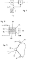
- the block diagram according to FIG. 1 corresponds to that shown and described in DE 42 21 739 A1 mentioned in the introduction.
- a transmission coil SSP is then fed with appropriate currents.
- the transmitter coil generates a similar (primary) magnetic field in the organism O, which is out of phase with the current in the transmitter coil.
- This primary magnetic field generates a (secondary) voltage in the organism O, which in turn triggers a corresponding (secondary) current flow in the organism, the course of which is the first derivative of the primary magnetic field.
- the (secondary) current builds up a (secondary) magnetic field, the time course of which corresponds to the secondary current flow course.
- the secondary magnetic field induces a current in a measuring coil MSP (FIG. 3), which is the first derivative of the time profile of the secondary current and thus the second derivative of the primary current that has flowed in the transmitter coil.
- FIG. 2 shows in a pulse schedule the time profile of the current causing the primary magnetic field in the transmitter coil SSP.
- tried and tested values for the duration of the individual pulses and pulse pauses are entered in the pulse schedule in milliseconds.
- the form of the so-called basic pulse which has a repetition frequency of, for example, 200 Hz and has an exponential roof profile, is reproduced in the pulse schedule under a).
- the basic pulse is not constantly sent out. Rather, as shown under b), there is a pulse pause for every four basic pulses. Three such pulse packets, each consisting of four basic pulses and the corresponding pulse pauses, are sent in succession, as shown under c), followed by a further pulse pause. As shown under d), nine such packets of three are sent in succession, followed by a further pulse pause. Then it repeats itself the expiration for a period of several minutes, for example of two minutes.
- the secondary fields triggered by the primary signal and its magnetic field in the organism O are recorded with a device according to the invention, for which a block diagram is shown in FIG.
- the basic structure corresponds to that of FIG. 14 of DE 42 21 739 A1 mentioned in the introduction.
- a memory circuit SP is connected to the output of the blanking circuit SCH and is used to store secondary field signals which are received via the measuring coil MSP after the individual basic pulses. This is in each case in the pulse pause of approximately 0.5 milliseconds after the individual basic pulse (see FIG. 2a). Since a current peak occurs in the measuring coil when the basic pulse is returned to the value zero and does not correspond to the secondary field signal sought, the connection to the memory SP is only established after this current peak has subsided.
- a corresponding time-delayed trigger pulse is derived from the basic pulse, as shown in FIG. 2, which is used for switching through from the measuring coil to the evaluation circuit AW with the memory SP, for the time until the beginning of the next basic pulse .
- a sequence of secondary field signals is produced, which are stored in the memory SP for further evaluation.
- FIG. 4 The course of such a secondary field signal is shown in FIG. 4, in which time values and amplitude values are plotted on the abscissa. It can be seen from this that the secondary field signal is relatively weak and consequently interfering signals such as noise and external interference fields can lead to significant measurement errors. This is equivalent to an insufficient signal / noise ratio.
- the form shown in FIG. 4 is that of a measured secondary field signal. In itself can to derive the secondary field signals from any pulses of the primary pulse train. However, it has proven advantageous to use the sequence of basic pulses for the derivation, which results in a sequence frequency of, for example, 200 Hz for the conditions shown in FIG.
- the fade-out switch SCH is closed by the trigger pulse only during the time of the secondary field signal of interest here. This not only suppresses the voltage peaks shown in dashed lines at the end of the individual pulse - see FIG. 4 - but also other unwanted signals occurring in the suppression period.
- secondary field signals occur in succession, usually as signals in analog form.
- a magnetic tape recorder is used as the memory, as shown in FIG. 5, the individual signals are recorded geometrically one after the other on the magnetic tape. As a result, they can be processed further in a simple manner.
- a sequence of individual recordings can be combined into a sum signal by means of a correlation method, which has a considerably better signal / noise ratio than the individual recorded signal.
- the correlation technique is generally known per se from transmission technology and is dealt with in detail and with sources, for example in the book “Korrelationstechnik" by Lange, 1960, VEB-Verlag, Berlin, especially on pages 348 and 353.
- phase-synchronous interference signals can also be selectively removed from the sum signal by cutting them out of the sum signal with a time window technique, so to speak. This gives a signal that can be used well for further evaluation.
- Another magnetic tape recorder MAZ2 is fed from the output of the magnetic tape recorder MAZ1.
- the magnetic tape of MAZ2 which is designed as a closed loop, has such a loop length and its tape speed is matched to that of MAZ1 such that successive secondary field signals from MAZ1 are always written to the same tape section in MAZ2. It is important to ensure that the tape in MAZ2 is not deleted between the individual registrations. To ensure exact time and phase synchronism, it is recommended - as indicated by a dashed line - to synchronize, for example, with the trigger signal which is used to actuate the blanking circuit SCH (FIG. 3).
- the sum signal can be brought from a readout head from MAZ2 to the actual measuring device ME.
- the measuring device ME can be an oscilloscope, a measuring device for determining the maximum amplitude of the signal or an integrator for determining the surface area covered by the secondary field signal - see FIG. 4 - and thus its energy content.
- the phase and time synchronism between MAZ1 and MAZ2 can also be ensured by deriving the synchronization of MAZ2 from the signal output of MAZ1.
- the trigger signal or a synchronizing signal can also be recorded, which is evaluated in MAZ2 for synchronization. This path also makes it possible to separate the actual signal acquisition via the measuring coil MSP from the actual evaluation via MAZ2.
- the secondary field signals are sampled in a sampler SA with a correspondingly high sampling frequency.
- the individual samples are converted into a digital signal in a so-called analog-digital converter A / D.
- a sequence of digital signals is thus obtained in a manner known per se, each of which represents the amplitude value of a sample and which can be stored in a memory for further processing, so to speak. It is advisable to write the digital signals of successive secondary field signals into successive lines of a memory SPM organized in the manner of a matrix, so that the individual digitally written secondary field signals are superimposed in the matrix.
- the cleaned signal BS can then be taken from the sum store SSP. This can be converted into an analog signal in a manner known per se via a digital-to-analog converter and can be used as explained with reference to FIG. 5. However, it can also be correspondingly evaluated in a manner known per se in the digital signal level.
- Reading from the memory matrix can be done serially, as can writing the results from SUM into the sum memory SSP. Man This means that fewer connections between SPM, SUM and SSP are required in a manner known per se.
- the clock signals for the individual circuit components (SA, A / D, SPM, SSP, SUM, D / A) required for execution in a manner known per se are supplied by a common clock generator TG via control signal derivation circuit STA in a manner known per se .
- the evaluation of these correlated quantities takes place via the measurement of the area in the secondary field course, i.e. the feedback pulse-voltage-time curve, i.e. the feedback pulse area added up within several pulse cascades, each consisting of 4 pulse cycles.
- This area value can be displayed continuously as a general assessment of the current blood flow.
- the change, in particular the increase, of the respectively added area value per pulse cascade compared to the area value of the last pulse cascade is a decisive effect information of the physical therapy system or triggered by pharmaceuticals (blood circulation promotion) and sports and the like. It is therefore advisable to make them visible in a separate display device.
- the area value takes on a higher value per unit of time, in particular, if, compared to the initial state, there is a higher blood flow and / or if the interfaces are not excessively polarized, there is a higher lymph flow.
- the applied amplitude and duration of the magnetic field of the medication, the movement etc., i.e. the dose, can be precisely assessed by the effect on the organism.
- the measurement may be strongly modulated by the breathing movement, because the distance between the measuring coil and the organism changes if no precautions are taken. This can be disruptive, especially with longer measuring cycles.
- One way to remedy this difficulty is to provide the measuring coil with means for firmly anchoring it to the organism.
- Another possibility is based on the fact that the respiratory rate is significantly different from the repetition rate of the secondary field signals.
- You can now, for example, using infrared light barriers Specify certain breathing time phases in which the distance between measuring coil MSP and breathing organism O is within certain limit values and only supply the secondary field signals recorded by MSP for evaluation in these time phases, for example by assigning SCH another blanking switch SCH2 - in FIG. 3 shown in dashed lines - which only switches through in these time phases.
- an external memory such as a patient card
- This patient card can be a card with a memory chip, as is generally known per se, for example through the book "Chipcard Technology, Security, Applications” by Fietta, Verlag Dr. Alfred Wegig, 1989, Heidelberg (especially the note on page 132 for such purposes).
- the device for storing data in the external memory is provided with a locking device which only enables the device to be put into operation if the external memory is in the receptacle of the device intended for it and is recordable is. This is indicated in FIG. 7 by a feedback contact MRK or switch, which enables the device to operate via a feedback line ML.
- Such locks are known, for example, from the art of floppy disk drives of personal computers, so that further details are not necessary.
- the sum of all differences in the pulse cycles, that is to say all the increases, is recorded over a therapy time or measurement time of, for example, 7 minutes per treatment.
- the card is designed as a visually readable card, it is advisable to construct the card with regard to the data in such a way that data of a treatment day are recorded in one line and these lines of the day are written one below the other. For three measurements per day or 24 hours and ten consecutive days of treatment, the form of presentation shown is the result. The differences from the respective initial value and the associated final value are entered, for example, as a measuring bar MB.
- a memory provides a further evaluation option for the secondary field signal. If a differentiating element is connected to the memory SP (FIG. 3), a signal is available at its output. which enables statements to be made about the fine structure of the secondary field signal, as has been known for years in a similar form for the evaluation of electrocardiograms. This not only makes it easier to see the action mechanisms, but also the effects of ions to be transported in an organism by means of the magnetic fields.
- the differentiating element is expediently connected downstream of the memory SP and upstream of the actual measuring device. Its output signal can also be stored in a memory for further processing. The course of a signal obtainable by differentiation is shown in dotted lines in FIG. It is also possible to switch on the differentiation in front of the memory and to store the differentiation result in the memory for further use.
- the time of exposure to an organism is of considerable importance. Since the sleep hormone melatonin can be suppressed by magnetic fields, exposure to the need to sleep is to be avoided or indicated in the case of a need to stay awake. Since the adrenaline level for effects is still influential, it is advisable to set the time in the late morning (11 00 +/- 2 hours) and / or in the late afternoon (16 00 +/- 2 hours), because in these Periods of adrenaline levels are highest in the circadian rhythm of humans.
- a time switch ZS as shown schematically in FIG. 9, which, for example, supplies the operating voltage U b for the evaluation circuit AW and / or other circuit parts of the device, such as the summing memory, but in particular the generator for supplying the Magnetic field coil interrupts outside of the times mentioned and thus keeps the device out of operation.
- the magnetic field exposure of an organism leads to an increased oxygen diffusion due to an increased oxygen partial pressure in the tissue. It leads to dilation of the blood vessels. A temperature increase also occurs.
- the individual signals can therefore be used in addition to a sensor that responds to the secondary magnetic field, and also chemosensors, in particular gas sensors and / or sensors that respond to heat radiation. These different sensors can be used alone, but also in combination with each other.
- FIG. 10 shows a schematic section through a gas sensor as used, for example, in the device G 818 of the "Gesellschaft für Elbau” in Dortmund.
- a working electrode AEL, a reference electrode REL and a counter electrode GEL are arranged in a housing GEH having a gas-permeable membrane MEMB.
- the space between the electrodes is filled with a corresponding electrolyte ELY, the reaction of which with the gas introduced into the sensor through the membrane triggers a change in the electrical values given between the electrodes.
- the G 818 device is known, inter alia, for nitrogen monoxide measurement in motor vehicle engines.
- This sensor is a semiconductor sensor in which the current flowing through it serves as a measured variable. The generated on one of a voltage corresponding to the gas concentration, which serves as a signal.
- the gas sensor is expediently integrated into a breathing mask which, in the case of a tried-and-tested pattern intended to enclose the nose and chin area of a person, as shown in FIG. 11, has three connections.
- a first connection A1 is used to connect to a pressure pump, not shown, which presses ambient air into the breathing mask.
- a second connection A2 contains the gas sensor GS, from which an electrical line for the decrease in the electrical quantity of the gas sensor leads to the device, not shown.
- a third connection A3 contains a pressure relief valve ÜV, which ensures constant pressure in the breathing mask and the gas sensor, thus clearly reproducible measuring conditions.
- the pressure generated by the pressure pump connected to the breathing mask, not shown in the drawing, should be low and only high enough to ensure a safe escape of the breathing air in the area of the gas sensor GS.
- An overpressure between about 20 and about 80 millibars in relation to the outside air has proven to be advantageous.
- a pressure pump which is of the gas mask type and has a breathing inlet valve and a breathing air outlet valve.
- the gas sensor is to be arranged in the airway of the breathing outlet, similar to FIG. 11.
- this type of breathing mask requires a certain additional energy expenditure by the organism when breathing.
- the change in breathing air triggered by a magnetic field exposure is somewhat delayed compared to the exposure period (a few minutes) because not only the organism, but also the gas sensor takes a certain amount of time to respond.
- the reaction is clear Recognizable, especially if, according to the time window technique explained with reference to FIG. 3, only useful signals for the measurement are masked out and fed to the memory for summation as individual signals.
- the signal at the output is visualized by means of an oscillographic display, a signal representing the change in the gas concentration can be clearly recognized, the duration of which corresponds relatively well to the preceding exposure time of the magnetic pulse.
- the device according to the invention is particularly important because it enables monitoring and control of the magnetic field exposure. Excessive exposure can exceed the regulatory capacity of an organism (eg Ca ++ excess in cells). In this case, pathological effects are expected. However, the diffusion of nitrogen monoxide in the lungs of an organism can then serve as an indicator of unphysiological moments.
Landscapes
- Health & Medical Sciences (AREA)
- Life Sciences & Earth Sciences (AREA)
- Physics & Mathematics (AREA)
- Engineering & Computer Science (AREA)
- Veterinary Medicine (AREA)
- Public Health (AREA)
- General Health & Medical Sciences (AREA)
- Animal Behavior & Ethology (AREA)
- Biomedical Technology (AREA)
- Molecular Biology (AREA)
- Pathology (AREA)
- Biophysics (AREA)
- Heart & Thoracic Surgery (AREA)
- Medical Informatics (AREA)
- Radiology & Medical Imaging (AREA)
- Surgery (AREA)
- Nuclear Medicine, Radiotherapy & Molecular Imaging (AREA)
- General Physics & Mathematics (AREA)
- Endocrinology (AREA)
- Condensed Matter Physics & Semiconductors (AREA)
- Immunology (AREA)
- Vascular Medicine (AREA)
- Magnetic Treatment Devices (AREA)
- Measuring Magnetic Variables (AREA)
- Magnetic Resonance Imaging Apparatus (AREA)
- Measurement And Recording Of Electrical Phenomena And Electrical Characteristics Of The Living Body (AREA)
- Measuring And Recording Apparatus For Diagnosis (AREA)
- Investigating Or Analyzing Materials By The Use Of Magnetic Means (AREA)
Applications Claiming Priority (3)
| Application Number | Priority Date | Filing Date | Title |
|---|---|---|---|
| DE4335102A DE4335102A1 (de) | 1993-10-14 | 1993-10-14 | Einrichtung zur Ermittlung der Wirkung gepulster Magnetfelder auf einen Organismus |
| DE4335102 | 1993-10-14 | ||
| PCT/EP1994/003325 WO1995010228A1 (de) | 1993-10-14 | 1994-10-08 | Einrichtung zur ermittlung der wirkung gepulster magnetfelder auf einen organismus |
Publications (2)
| Publication Number | Publication Date |
|---|---|
| EP0729318A1 EP0729318A1 (de) | 1996-09-04 |
| EP0729318B1 true EP0729318B1 (de) | 1997-05-07 |
Family
ID=6500170
Family Applications (1)
| Application Number | Title | Priority Date | Filing Date |
|---|---|---|---|
| EP94929522A Expired - Lifetime EP0729318B1 (de) | 1993-10-14 | 1994-10-08 | Einrichtung zur ermittlung der wirkung gepulster magnetfelder auf einen organismus |
Country Status (16)
| Country | Link |
|---|---|
| US (1) | US5877627A (da) |
| EP (1) | EP0729318B1 (da) |
| JP (1) | JPH09503684A (da) |
| AT (1) | ATE152595T1 (da) |
| AU (1) | AU7854794A (da) |
| CA (1) | CA2172364A1 (da) |
| DE (3) | DE4335102A1 (da) |
| ES (1) | ES2101577T3 (da) |
| GR (1) | GR3024247T3 (da) |
| IL (1) | IL111164A (da) |
| SA (1) | SA94150271A (da) |
| TN (1) | TNSN94108A1 (da) |
| TR (1) | TR28599A (da) |
| TW (1) | TW281729B (da) |
| WO (1) | WO1995010228A1 (da) |
| ZA (1) | ZA947484B (da) |
Cited By (8)
| Publication number | Priority date | Publication date | Assignee | Title |
|---|---|---|---|---|
| DE10157024A1 (de) * | 2001-11-21 | 2003-05-28 | Fischer Ag Triesenberg Dr | Arbeitsverfahren zum Betreiben einer Vorrichtung zur optimierten Stimulation eines oder mehrerer Probanden mittels pulsierender elektromagnetischer und/oder elektrischer Felder |
| DE10304085A1 (de) * | 2003-01-31 | 2004-08-12 | Günther, Andreas | Anordnung und Verfahren zur Durchführung einer Magnetfeldtherapie |
| DE102004002681A1 (de) * | 2003-06-06 | 2004-12-30 | Software + Systeme Erfurt Gmbh | Anordnung zur Erzeugung frequenzmodulierter elektrischer/elektromagnetischer Wechselfelder niedriger Intensität zur Probandenstimulation und Arbeitsverfahren zum Betrieb einer derartigen Anordnung |
| EP2050481A1 (de) | 2007-10-17 | 2009-04-22 | Wolf A. Prof. Dr. Kafka | Vorrichtung zur Magnetfeldtherapie und zu applizierendes Magnetfeldsignal |
| DE202016008332U1 (de) | 2016-11-24 | 2017-09-04 | Bemer Int. AG | Vorrichtung zur Beeinflussung biologischer Abläufe in einem lebenden Gewebe |
| DE202016008331U1 (de) | 2016-11-24 | 2017-09-04 | Bemer Int. AG | Vorrichtung zur Beeinflussung biologischer Abläufe in einem lebenden Gewebe |
| DE102020117033B3 (de) | 2020-06-29 | 2021-09-16 | Centropix Global Ag | Vorrichtung zur Magnetfeldtherapie |
| DE102021101671A1 (de) | 2021-01-26 | 2022-07-28 | Centropix Global Ag | Vorrichtung zur Magnetfeldtherapie |
Families Citing this family (20)
| Publication number | Priority date | Publication date | Assignee | Title |
|---|---|---|---|---|
| DE19642149A1 (de) * | 1996-10-12 | 1998-04-23 | Telefunken Microelectron | System zur Datenübertragung |
| DE29709094U1 (de) * | 1997-05-23 | 1998-09-17 | Kiontke, Siegfried, Dr., 81245 München | Gerät für die Bioresonanz-Therapie |
| DE10130296B4 (de) * | 2001-06-22 | 2004-07-01 | It Dr. Gambert Gmbh | Vorrichtung zur Messung des Partialdrucks von Stickstoffmonoxid (NO) im Atemgas |
| DE10303080A1 (de) * | 2003-01-27 | 2004-09-02 | Siemens Ag | Vorrichtung und Verfahren zur Messung eines aus einem Körper ausgestoßenen Gases |
| US20130218235A9 (en) * | 2005-03-07 | 2013-08-22 | Arthur A. Pilla | Excessive fibrous capsule formation and capsular contracture apparatus and method for using same |
| US8961385B2 (en) | 2003-12-05 | 2015-02-24 | Ivivi Health Sciences, Llc | Devices and method for treatment of degenerative joint diseases with electromagnetic fields |
| US9427598B2 (en) | 2010-10-01 | 2016-08-30 | Rio Grande Neurosciences, Inc. | Method and apparatus for electromagnetic treatment of head, cerebral and neural injury in animals and humans |
| US9656096B2 (en) | 2003-12-05 | 2017-05-23 | Rio Grande Neurosciences, Inc. | Method and apparatus for electromagnetic enhancement of biochemical signaling pathways for therapeutics and prophylaxis in plants, animals and humans |
| US20110112352A1 (en) * | 2003-12-05 | 2011-05-12 | Pilla Arthur A | Apparatus and method for electromagnetic treatment |
| US7744524B2 (en) * | 2003-12-05 | 2010-06-29 | Ivivi Health Sciences, Llc | Apparatus and method for electromagnetic treatment of plant, animal, and human tissue, organs, cells, and molecules |
| US9440089B2 (en) | 2003-12-05 | 2016-09-13 | Rio Grande Neurosciences, Inc. | Apparatus and method for electromagnetic treatment of neurological injury or condition caused by a stroke |
| US9415233B2 (en) | 2003-12-05 | 2016-08-16 | Rio Grande Neurosciences, Inc. | Apparatus and method for electromagnetic treatment of neurological pain |
| US10350428B2 (en) | 2014-11-04 | 2019-07-16 | Endonovo Therapetics, Inc. | Method and apparatus for electromagnetic treatment of living systems |
| US9433797B2 (en) | 2003-12-05 | 2016-09-06 | Rio Grande Neurosciences, Inc. | Apparatus and method for electromagnetic treatment of neurodegenerative conditions |
| KR20070024533A (ko) | 2004-04-19 | 2007-03-02 | 아이비비 테크놀로지스, 아이엔씨. | 전자기 치료 장치 및 방법 |
| CA2564795A1 (en) * | 2004-04-26 | 2005-11-10 | Ivivi Technologies, Inc. | Electromagnetic treatment induction apparatus and method |
| US8343027B1 (en) | 2012-01-30 | 2013-01-01 | Ivivi Health Sciences, Llc | Methods and devices for providing electromagnetic treatment in the presence of a metal-containing implant |
| US9320913B2 (en) | 2014-04-16 | 2016-04-26 | Rio Grande Neurosciences, Inc. | Two-part pulsed electromagnetic field applicator for application of therapeutic energy |
| US10806942B2 (en) | 2016-11-10 | 2020-10-20 | Qoravita LLC | System and method for applying a low frequency magnetic field to biological tissues |
| CN114324247B (zh) * | 2022-01-12 | 2023-05-09 | 四川大学 | 基于量子弱测量的双通道探测的光学测量方法及应用 |
Family Cites Families (8)
| Publication number | Priority date | Publication date | Assignee | Title |
|---|---|---|---|---|
| US5073858A (en) * | 1984-12-10 | 1991-12-17 | Mills Randell L | Magnetic susceptibility imaging (msi) |
| DE3445047A1 (de) * | 1984-12-11 | 1986-06-19 | Peter Dipl.-Phys. Dr. 8000 München Mieg | Messanordnung zur bestimmung optimaler rueckwirkung zwischen elektromagnetischen wellen und gravitation und verfahren zur auswertung dieser messung fuer medizinische und biologische anwendung |
| US4819648A (en) * | 1985-10-28 | 1989-04-11 | The Johns Hopkins University | Non-invasive electromagnetic technique for monitoring time-trends of physiological changes at a particular location in the brain |
| DE3886044D1 (de) * | 1988-09-23 | 1994-01-13 | Siemens Ag | Einrichtung und Verfahren zur Messung von schwachen, orts- und zeitabhängigen Magnetfeldern. |
| US4985678A (en) * | 1988-10-14 | 1991-01-15 | Picker International, Inc. | Horizontal field iron core magnetic resonance scanner |
| GB9006320D0 (en) * | 1990-03-21 | 1990-05-16 | Gen Electric Co Plc | Nuclear magnetic resonance apparatus |
| DE4221739A1 (de) * | 1991-07-09 | 1993-01-14 | Fischer Ag | Vorrichtung zum transport von ionen, insbesondere protonen |
| US5212448A (en) * | 1991-08-09 | 1993-05-18 | General Electric Company | Nmr pulse sequence with burst rf excitation pulses having separately controlled phase |
-
1993
- 1993-10-14 DE DE4335102A patent/DE4335102A1/de not_active Ceased
-
1994
- 1994-09-26 ZA ZA947484A patent/ZA947484B/xx unknown
- 1994-10-04 IL IL111164A patent/IL111164A/xx not_active IP Right Cessation
- 1994-10-04 TW TW083109175A patent/TW281729B/zh active
- 1994-10-08 US US08/628,722 patent/US5877627A/en not_active Expired - Fee Related
- 1994-10-08 WO PCT/EP1994/003325 patent/WO1995010228A1/de not_active Ceased
- 1994-10-08 CA CA002172364A patent/CA2172364A1/en not_active Abandoned
- 1994-10-08 AT AT94929522T patent/ATE152595T1/de not_active IP Right Cessation
- 1994-10-08 DE DE9490308U patent/DE9490308U1/de not_active Expired - Lifetime
- 1994-10-08 AU AU78547/94A patent/AU7854794A/en not_active Abandoned
- 1994-10-08 ES ES94929522T patent/ES2101577T3/es not_active Expired - Lifetime
- 1994-10-08 EP EP94929522A patent/EP0729318B1/de not_active Expired - Lifetime
- 1994-10-08 DE DE59402683T patent/DE59402683D1/de not_active Expired - Lifetime
- 1994-10-08 JP JP7511263A patent/JPH09503684A/ja active Pending
- 1994-10-14 TR TR01077/94A patent/TR28599A/xx unknown
- 1994-10-14 TN TNTNSN94108A patent/TNSN94108A1/ar unknown
- 1994-10-30 SA SA94150271A patent/SA94150271A/ar unknown
-
1997
- 1997-07-25 GR GR970401893T patent/GR3024247T3/el unknown
Cited By (18)
| Publication number | Priority date | Publication date | Assignee | Title |
|---|---|---|---|---|
| DE10157024A1 (de) * | 2001-11-21 | 2003-05-28 | Fischer Ag Triesenberg Dr | Arbeitsverfahren zum Betreiben einer Vorrichtung zur optimierten Stimulation eines oder mehrerer Probanden mittels pulsierender elektromagnetischer und/oder elektrischer Felder |
| WO2003043695A2 (de) | 2001-11-21 | 2003-05-30 | Dr. Fischer Ag | Arbeitsverfahren zum betreiben einer vorrichtung zur optimierten stimulation eines oder mehrerer probanden mittels pulsierender elektromagnetischer und/oder elektrischer felder |
| EP1446194A2 (de) * | 2001-11-21 | 2004-08-18 | Dr. Fischer AG | Arbeitsverfahren zum betreiben einer vorrichtung zur optimierten stimulation eines oder mehrerer probanden mittels pulsierender elektromagnetischer und/oder elektrischer felder |
| DE10157024B4 (de) * | 2001-11-21 | 2015-10-15 | Quanten-Medicine Ag | Vorrichtung zur Erzeugung von pulsierenden elektromagnetischen und/oder elektrischen Feldern |
| DE10304085A1 (de) * | 2003-01-31 | 2004-08-12 | Günther, Andreas | Anordnung und Verfahren zur Durchführung einer Magnetfeldtherapie |
| DE102004002681A1 (de) * | 2003-06-06 | 2004-12-30 | Software + Systeme Erfurt Gmbh | Anordnung zur Erzeugung frequenzmodulierter elektrischer/elektromagnetischer Wechselfelder niedriger Intensität zur Probandenstimulation und Arbeitsverfahren zum Betrieb einer derartigen Anordnung |
| EP2050481A1 (de) | 2007-10-17 | 2009-04-22 | Wolf A. Prof. Dr. Kafka | Vorrichtung zur Magnetfeldtherapie und zu applizierendes Magnetfeldsignal |
| DE202016008331U1 (de) | 2016-11-24 | 2017-09-04 | Bemer Int. AG | Vorrichtung zur Beeinflussung biologischer Abläufe in einem lebenden Gewebe |
| DE202016008332U1 (de) | 2016-11-24 | 2017-09-04 | Bemer Int. AG | Vorrichtung zur Beeinflussung biologischer Abläufe in einem lebenden Gewebe |
| DE102016122689A1 (de) | 2016-11-24 | 2018-05-24 | Bemer Int. AG | Vorrichtung zur Beeinflussung biologischer Abläufe in einem lebenden Gewebe |
| DE102016122691A1 (de) | 2016-11-24 | 2018-05-24 | Bemer Int. AG | Vorrichtung zur Beeinflussung biologischer Abläufe in einem lebenden Gewebe |
| WO2018095589A1 (de) | 2016-11-24 | 2018-05-31 | Bemer Int. AG | Vorrichtung zur beeinflussung biologischer abläufe in einem lebenden gewebe |
| WO2018095590A1 (de) | 2016-11-24 | 2018-05-31 | Bemer Int. AG | Vorrichtung zur beeinflussung biologischer abläufe in einem lebenden gewebe |
| US11090504B2 (en) | 2016-11-24 | 2021-08-17 | Bemer Int. AG | Device for influencing biological processes in living tissue |
| US11147981B2 (en) | 2016-11-24 | 2021-10-19 | Bemer Int. AG | Device for influencing biological processes in living tissue |
| DE102020117033B3 (de) | 2020-06-29 | 2021-09-16 | Centropix Global Ag | Vorrichtung zur Magnetfeldtherapie |
| WO2022002493A1 (en) | 2020-06-29 | 2022-01-06 | Centropix Global Ag | Device for magnetic field therapy |
| DE102021101671A1 (de) | 2021-01-26 | 2022-07-28 | Centropix Global Ag | Vorrichtung zur Magnetfeldtherapie |
Also Published As
| Publication number | Publication date |
|---|---|
| ZA947484B (en) | 1995-05-15 |
| TNSN94108A1 (ar) | 1995-09-21 |
| EP0729318A1 (de) | 1996-09-04 |
| AU7854794A (en) | 1995-05-04 |
| CA2172364A1 (en) | 1995-04-20 |
| GR3024247T3 (en) | 1997-10-31 |
| TW281729B (da) | 1996-07-21 |
| JPH09503684A (ja) | 1997-04-15 |
| DE9490308U1 (de) | 1996-10-02 |
| DE4335102A1 (de) | 1995-04-20 |
| IL111164A0 (en) | 1994-12-29 |
| TR28599A (tr) | 1996-11-07 |
| US5877627A (en) | 1999-03-02 |
| ATE152595T1 (de) | 1997-05-15 |
| DE59402683D1 (de) | 1997-06-12 |
| WO1995010228A1 (de) | 1995-04-20 |
| IL111164A (en) | 1997-04-15 |
| ES2101577T3 (es) | 1997-07-01 |
| SA94150271A (ar) | 2005-12-03 |
Similar Documents
| Publication | Publication Date | Title |
|---|---|---|
| EP0729318B1 (de) | Einrichtung zur ermittlung der wirkung gepulster magnetfelder auf einen organismus | |
| Fox et al. | Electroencephalogram asymmetry in response to the approach of a stranger and maternal separation in 10-month-old infants. | |
| Lykken | Neuropsychology and Psychophysiology in Personality Research: Part II. Psychophysiological Techniques and Personality Theory | |
| US3696808A (en) | Method and system for brain wave analysis | |
| Sams et al. | Cortical activity elicited by changes in auditory stimuli: Different sources for the magnetic N1OOm and mismatch responses | |
| EP0452276B1 (de) | Blutflussmessgerät | |
| Prechtl et al. | Organization of physiological parameters in normal and neurologically abnormal infants | |
| Gritz et al. | Physiological and psychological effects of methadone in man | |
| Depiano et al. | Hypnosis as an aid to recall of meaningful information presented under three types of arousal | |
| DE69226922T2 (de) | Nichtmagnetischer Taststimulator und Vorrichtung zur Anwendung eines solchen Taststimulators | |
| LOBITZ et al. | Glycogen response in human epidermal basal cell | |
| Haykin et al. | Monitoring neuronal oscillations and signal transmission between cortical regions using time-frequency analysis of electroencephalographic activity | |
| Maxwell et al. | Reading ability and brain function: A simple statistical model | |
| Korba | The rate of inner speech | |
| Widacki | Discoverers of the galvanic skin response | |
| Zarjam et al. | Evaluation of working memory load using EEG signals | |
| Thompson et al. | Bioelectric Recording Techniques: Electroencephalography and Human Brain Potentials | |
| Schallek et al. | Power spectrum analysis of drug effects on electroencephalogram of cat | |
| McFarland et al. | Effects of pulsed gamma-neutron irradiation on the EEG and behavior of the monkey | |
| Sem-Jacobsen et al. | Simultaneous focal intracerebral blood flow measurements in man around 18 chronically implanted electrodes | |
| Hämäläinen | Interpretation of neuromagnetic measurements: modeling and statistical considerations | |
| Lounasmaa | Medical applications of SQUIDs in neuro-and cardiomagnetism | |
| Kerr et al. | A PDP-12 system for on-line acquisition of heart rate data | |
| JPS6021740A (ja) | 生体機能検査装置 | |
| Schwartz | An Investigation of the Effects of Isolation on Time Perception and Its Physiological Correlates |
Legal Events
| Date | Code | Title | Description |
|---|---|---|---|
| PUAI | Public reference made under article 153(3) epc to a published international application that has entered the european phase |
Free format text: ORIGINAL CODE: 0009012 |
|
| 17P | Request for examination filed |
Effective date: 19960309 |
|
| AK | Designated contracting states |
Kind code of ref document: A1 Designated state(s): AT BE CH DE DK ES FR GB GR IE IT LI LU MC NL PT SE |
|
| AX | Request for extension of the european patent |
Free format text: LT PAYMENT 960309;SI PAYMENT 960309 |
|
| RAX | Requested extension states of the european patent have changed |
Free format text: LT PAYMENT 960309;SI PAYMENT 960309 |
|
| GRAG | Despatch of communication of intention to grant |
Free format text: ORIGINAL CODE: EPIDOS AGRA |
|
| GRAH | Despatch of communication of intention to grant a patent |
Free format text: ORIGINAL CODE: EPIDOS IGRA |
|
| 17Q | First examination report despatched |
Effective date: 19961022 |
|
| GRAH | Despatch of communication of intention to grant a patent |
Free format text: ORIGINAL CODE: EPIDOS IGRA |
|
| GRAA | (expected) grant |
Free format text: ORIGINAL CODE: 0009210 |
|
| AK | Designated contracting states |
Kind code of ref document: B1 Designated state(s): AT BE CH DE DK ES FR GB GR IE IT LI LU MC NL PT SE |
|
| AX | Request for extension of the european patent |
Free format text: LT PAYMENT 960309;SI PAYMENT 960309 |
|
| PG25 | Lapsed in a contracting state [announced via postgrant information from national office to epo] |
Ref country code: DK Effective date: 19970507 |
|
| REF | Corresponds to: |
Ref document number: 152595 Country of ref document: AT Date of ref document: 19970515 Kind code of ref document: T |
|
| REG | Reference to a national code |
Ref country code: CH Ref legal event code: EP |
|
| GBT | Gb: translation of ep patent filed (gb section 77(6)(a)/1977) |
Effective date: 19970516 |
|
| REF | Corresponds to: |
Ref document number: 59402683 Country of ref document: DE Date of ref document: 19970612 |
|
| REG | Reference to a national code |
Ref country code: ES Ref legal event code: FG2A Ref document number: 2101577 Country of ref document: ES Kind code of ref document: T3 |
|
| REG | Reference to a national code |
Ref country code: IE Ref legal event code: FG4D Free format text: 73861 |
|
| PG25 | Lapsed in a contracting state [announced via postgrant information from national office to epo] |
Ref country code: PT Effective date: 19970807 |
|
| ET | Fr: translation filed | ||
| REG | Reference to a national code |
Ref country code: GR Ref legal event code: FG4A Free format text: 3024247 |
|
| PG25 | Lapsed in a contracting state [announced via postgrant information from national office to epo] |
Ref country code: LU Free format text: LAPSE BECAUSE OF NON-PAYMENT OF DUE FEES Effective date: 19971008 |
|
| PLBE | No opposition filed within time limit |
Free format text: ORIGINAL CODE: 0009261 |
|
| STAA | Information on the status of an ep patent application or granted ep patent |
Free format text: STATUS: NO OPPOSITION FILED WITHIN TIME LIMIT |
|
| PG25 | Lapsed in a contracting state [announced via postgrant information from national office to epo] |
Ref country code: IE Free format text: LAPSE BECAUSE OF NON-PAYMENT OF DUE FEES Effective date: 19980330 |
|
| REG | Reference to a national code |
Ref country code: IE Ref legal event code: FD4D Ref document number: 73861 Country of ref document: IE |
|
| 26N | No opposition filed | ||
| PGFP | Annual fee paid to national office [announced via postgrant information from national office to epo] |
Ref country code: MC Payment date: 19981026 Year of fee payment: 5 |
|
| PG25 | Lapsed in a contracting state [announced via postgrant information from national office to epo] |
Ref country code: MC Free format text: LAPSE BECAUSE OF NON-PAYMENT OF DUE FEES Effective date: 20000430 |
|
| REG | Reference to a national code |
Ref country code: GB Ref legal event code: IF02 |
|
| REG | Reference to a national code |
Ref country code: CH Ref legal event code: PFA Owner name: DR. FISCHER AG Free format text: DR. FISCHER AG#JOSEF-RHEINBERGER-STRASSE 6#FL-9490 VADUZ (LI) -TRANSFER TO- DR. FISCHER AG#LAVADINA 145 B#9497 TRIESENBERG (LI) |
|
| REG | Reference to a national code |
Ref country code: CH Ref legal event code: PUE Owner name: QUANTEN-MEDICINE AKTIENGESELLSCHAFT Free format text: DR. FISCHER AG#LAVADINA 145 B#9497 TRIESENBERG (LI) -TRANSFER TO- QUANTEN-MEDICINE AKTIENGESELLSCHAFT#INDUSTRIESTRASSE 651#9492 ESCHEN (LI) |
|
| REG | Reference to a national code |
Ref country code: GB Ref legal event code: 732E |
|
| NLS | Nl: assignments of ep-patents |
Owner name: QUANTEN-MEDICINE AKTIENGESELLSCHAFT Effective date: 20080630 |
|
| REG | Reference to a national code |
Ref country code: FR Ref legal event code: TP |
|
| PGFP | Annual fee paid to national office [announced via postgrant information from national office to epo] |
Ref country code: SE Payment date: 20091029 Year of fee payment: 16 Ref country code: ES Payment date: 20091026 Year of fee payment: 16 Ref country code: DE Payment date: 20091126 Year of fee payment: 16 Ref country code: CH Payment date: 20091006 Year of fee payment: 16 Ref country code: AT Payment date: 20091027 Year of fee payment: 16 |
|
| PGFP | Annual fee paid to national office [announced via postgrant information from national office to epo] |
Ref country code: NL Payment date: 20091027 Year of fee payment: 16 |
|
| PGFP | Annual fee paid to national office [announced via postgrant information from national office to epo] |
Ref country code: IT Payment date: 20091027 Year of fee payment: 16 Ref country code: GB Payment date: 20091023 Year of fee payment: 16 Ref country code: FR Payment date: 20091110 Year of fee payment: 16 |
|
| PGFP | Annual fee paid to national office [announced via postgrant information from national office to epo] |
Ref country code: BE Payment date: 20091029 Year of fee payment: 16 |
|
| PGFP | Annual fee paid to national office [announced via postgrant information from national office to epo] |
Ref country code: GR Payment date: 20091030 Year of fee payment: 16 |
|
| BERE | Be: lapsed |
Owner name: *QUANTEN-MEDICINE A.G. Effective date: 20101031 |
|
| REG | Reference to a national code |
Ref country code: NL Ref legal event code: V1 Effective date: 20110501 |
|
| REG | Reference to a national code |
Ref country code: CH Ref legal event code: PL |
|
| GBPC | Gb: european patent ceased through non-payment of renewal fee |
Effective date: 20101008 |
|
| PG25 | Lapsed in a contracting state [announced via postgrant information from national office to epo] |
Ref country code: GR Free format text: LAPSE BECAUSE OF NON-PAYMENT OF DUE FEES Effective date: 20110503 Ref country code: FR Free format text: LAPSE BECAUSE OF NON-PAYMENT OF DUE FEES Effective date: 20101102 Ref country code: CH Free format text: LAPSE BECAUSE OF NON-PAYMENT OF DUE FEES Effective date: 20101031 Ref country code: LI Free format text: LAPSE BECAUSE OF NON-PAYMENT OF DUE FEES Effective date: 20101031 |
|
| REG | Reference to a national code |
Ref country code: FR Ref legal event code: ST Effective date: 20110630 |
|
| PG25 | Lapsed in a contracting state [announced via postgrant information from national office to epo] |
Ref country code: NL Free format text: LAPSE BECAUSE OF NON-PAYMENT OF DUE FEES Effective date: 20110501 Ref country code: GB Free format text: LAPSE BECAUSE OF NON-PAYMENT OF DUE FEES Effective date: 20101008 Ref country code: AT Free format text: LAPSE BECAUSE OF NON-PAYMENT OF DUE FEES Effective date: 20101008 Ref country code: BE Free format text: LAPSE BECAUSE OF NON-PAYMENT OF DUE FEES Effective date: 20101031 |
|
| PG25 | Lapsed in a contracting state [announced via postgrant information from national office to epo] |
Ref country code: SE Free format text: LAPSE BECAUSE OF NON-PAYMENT OF DUE FEES Effective date: 20101009 |
|
| REG | Reference to a national code |
Ref country code: ES Ref legal event code: FD2A Effective date: 20111118 |
|
| REG | Reference to a national code |
Ref country code: DE Ref legal event code: R119 Ref document number: 59402683 Country of ref document: DE Effective date: 20110502 |
|
| PG25 | Lapsed in a contracting state [announced via postgrant information from national office to epo] |
Ref country code: IT Free format text: LAPSE BECAUSE OF NON-PAYMENT OF DUE FEES Effective date: 20101008 |
|
| PG25 | Lapsed in a contracting state [announced via postgrant information from national office to epo] |
Ref country code: ES Free format text: LAPSE BECAUSE OF NON-PAYMENT OF DUE FEES Effective date: 20101009 |
|
| PG25 | Lapsed in a contracting state [announced via postgrant information from national office to epo] |
Ref country code: DE Free format text: LAPSE BECAUSE OF NON-PAYMENT OF DUE FEES Effective date: 20110502 |