EP0728228B1 - Cellule de production de fluor - Google Patents
Cellule de production de fluor Download PDFInfo
- Publication number
- EP0728228B1 EP0728228B1 EP95931296A EP95931296A EP0728228B1 EP 0728228 B1 EP0728228 B1 EP 0728228B1 EP 95931296 A EP95931296 A EP 95931296A EP 95931296 A EP95931296 A EP 95931296A EP 0728228 B1 EP0728228 B1 EP 0728228B1
- Authority
- EP
- European Patent Office
- Prior art keywords
- anode
- cell
- fluorine
- compartment
- electrolyte
- Prior art date
- Legal status (The legal status is an assumption and is not a legal conclusion. Google has not performed a legal analysis and makes no representation as to the accuracy of the status listed.)
- Expired - Lifetime
Links
- YCKRFDGAMUMZLT-UHFFFAOYSA-N Fluorine atom Chemical compound [F] YCKRFDGAMUMZLT-UHFFFAOYSA-N 0.000 title claims abstract description 95
- 229910052731 fluorine Inorganic materials 0.000 title claims abstract description 95
- 239000011737 fluorine Substances 0.000 title claims abstract description 95
- 239000003792 electrolyte Substances 0.000 claims description 55
- UFHFLCQGNIYNRP-UHFFFAOYSA-N Hydrogen Chemical compound [H][H] UFHFLCQGNIYNRP-UHFFFAOYSA-N 0.000 claims description 20
- 239000007789 gas Substances 0.000 claims description 20
- 239000000523 sample Substances 0.000 claims description 19
- OKTJSMMVPCPJKN-UHFFFAOYSA-N Carbon Chemical compound [C] OKTJSMMVPCPJKN-UHFFFAOYSA-N 0.000 claims description 17
- 239000001257 hydrogen Substances 0.000 claims description 17
- 229910052739 hydrogen Inorganic materials 0.000 claims description 17
- PXHVJJICTQNCMI-UHFFFAOYSA-N Nickel Chemical compound [Ni] PXHVJJICTQNCMI-UHFFFAOYSA-N 0.000 claims description 16
- 238000005868 electrolysis reaction Methods 0.000 claims description 16
- 229910052799 carbon Inorganic materials 0.000 claims description 15
- 239000002184 metal Substances 0.000 claims description 15
- 229910052751 metal Inorganic materials 0.000 claims description 15
- 238000000034 method Methods 0.000 claims description 15
- 238000004519 manufacturing process Methods 0.000 claims description 13
- 238000000576 coating method Methods 0.000 claims description 12
- 238000000926 separation method Methods 0.000 claims description 12
- 239000011248 coating agent Substances 0.000 claims description 11
- 238000010438 heat treatment Methods 0.000 claims description 8
- 229910052759 nickel Inorganic materials 0.000 claims description 8
- 239000000463 material Substances 0.000 claims description 7
- 239000004033 plastic Substances 0.000 claims description 4
- 229920003023 plastic Polymers 0.000 claims description 4
- 229910045601 alloy Inorganic materials 0.000 claims description 3
- 239000000956 alloy Substances 0.000 claims description 3
- 238000007750 plasma spraying Methods 0.000 claims description 3
- 238000003466 welding Methods 0.000 claims description 3
- 238000010285 flame spraying Methods 0.000 claims description 2
- 230000003287 optical effect Effects 0.000 claims description 2
- 238000005240 physical vapour deposition Methods 0.000 claims description 2
- 210000004027 cell Anatomy 0.000 description 68
- 238000010276 construction Methods 0.000 description 9
- 238000007789 sealing Methods 0.000 description 6
- KRHYYFGTRYWZRS-UHFFFAOYSA-N Fluorane Chemical compound F KRHYYFGTRYWZRS-UHFFFAOYSA-N 0.000 description 4
- 229910001209 Low-carbon steel Inorganic materials 0.000 description 4
- 230000000994 depressogenic effect Effects 0.000 description 4
- 229910000040 hydrogen fluoride Inorganic materials 0.000 description 4
- 238000006243 chemical reaction Methods 0.000 description 3
- 238000005260 corrosion Methods 0.000 description 3
- 230000007797 corrosion Effects 0.000 description 3
- XLYOFNOQVPJJNP-UHFFFAOYSA-N water Substances O XLYOFNOQVPJJNP-UHFFFAOYSA-N 0.000 description 3
- RYGMFSIKBFXOCR-UHFFFAOYSA-N Copper Chemical compound [Cu] RYGMFSIKBFXOCR-UHFFFAOYSA-N 0.000 description 2
- 230000003466 anti-cipated effect Effects 0.000 description 2
- 230000004323 axial length Effects 0.000 description 2
- 230000001680 brushing effect Effects 0.000 description 2
- 239000004568 cement Substances 0.000 description 2
- 238000001816 cooling Methods 0.000 description 2
- 229910052802 copper Inorganic materials 0.000 description 2
- 239000010949 copper Substances 0.000 description 2
- 238000010586 diagram Methods 0.000 description 2
- 238000007598 dipping method Methods 0.000 description 2
- 238000000605 extraction Methods 0.000 description 2
- 230000008014 freezing Effects 0.000 description 2
- 238000007710 freezing Methods 0.000 description 2
- 229910002804 graphite Inorganic materials 0.000 description 2
- 239000010439 graphite Substances 0.000 description 2
- 229910021385 hard carbon Inorganic materials 0.000 description 2
- 230000006798 recombination Effects 0.000 description 2
- 238000005215 recombination Methods 0.000 description 2
- 230000000630 rising effect Effects 0.000 description 2
- 239000002699 waste material Substances 0.000 description 2
- DDFHBQSCUXNBSA-UHFFFAOYSA-N 5-(5-carboxythiophen-2-yl)thiophene-2-carboxylic acid Chemical compound S1C(C(=O)O)=CC=C1C1=CC=C(C(O)=O)S1 DDFHBQSCUXNBSA-UHFFFAOYSA-N 0.000 description 1
- 229910000792 Monel Inorganic materials 0.000 description 1
- 238000005299 abrasion Methods 0.000 description 1
- PNEYBMLMFCGWSK-UHFFFAOYSA-N aluminium oxide Inorganic materials [O-2].[O-2].[O-2].[Al+3].[Al+3] PNEYBMLMFCGWSK-UHFFFAOYSA-N 0.000 description 1
- 238000005422 blasting Methods 0.000 description 1
- 230000005587 bubbling Effects 0.000 description 1
- 230000015556 catabolic process Effects 0.000 description 1
- 210000002421 cell wall Anatomy 0.000 description 1
- 239000000919 ceramic Substances 0.000 description 1
- 229910010293 ceramic material Inorganic materials 0.000 description 1
- 238000003486 chemical etching Methods 0.000 description 1
- 238000005229 chemical vapour deposition Methods 0.000 description 1
- 239000000470 constituent Substances 0.000 description 1
- 230000001595 contractor effect Effects 0.000 description 1
- 238000006731 degradation reaction Methods 0.000 description 1
- 230000000593 degrading effect Effects 0.000 description 1
- 230000000881 depressing effect Effects 0.000 description 1
- 229920001971 elastomer Polymers 0.000 description 1
- 238000010292 electrical insulation Methods 0.000 description 1
- 239000002360 explosive Substances 0.000 description 1
- 210000003414 extremity Anatomy 0.000 description 1
- 229920001973 fluoroelastomer Polymers 0.000 description 1
- 231100001261 hazardous Toxicity 0.000 description 1
- 150000002431 hydrogen Chemical class 0.000 description 1
- 238000009413 insulation Methods 0.000 description 1
- 230000001788 irregular Effects 0.000 description 1
- 238000011031 large-scale manufacturing process Methods 0.000 description 1
- 239000011244 liquid electrolyte Substances 0.000 description 1
- 210000003141 lower extremity Anatomy 0.000 description 1
- 230000008018 melting Effects 0.000 description 1
- 238000002844 melting Methods 0.000 description 1
- 239000000203 mixture Substances 0.000 description 1
- QKCGXXHCELUCKW-UHFFFAOYSA-N n-[4-[4-(dinaphthalen-2-ylamino)phenyl]phenyl]-n-naphthalen-2-ylnaphthalen-2-amine Chemical compound C1=CC=CC2=CC(N(C=3C=CC(=CC=3)C=3C=CC(=CC=3)N(C=3C=C4C=CC=CC4=CC=3)C=3C=C4C=CC=CC4=CC=3)C3=CC4=CC=CC=C4C=C3)=CC=C21 QKCGXXHCELUCKW-UHFFFAOYSA-N 0.000 description 1
- 230000007935 neutral effect Effects 0.000 description 1
- 238000012261 overproduction Methods 0.000 description 1
- 230000035515 penetration Effects 0.000 description 1
- 230000035699 permeability Effects 0.000 description 1
- 239000004810 polytetrafluoroethylene Substances 0.000 description 1
- 229920001343 polytetrafluoroethylene Polymers 0.000 description 1
- 238000002360 preparation method Methods 0.000 description 1
- 238000007788 roughening Methods 0.000 description 1
- 238000005507 spraying Methods 0.000 description 1
- 238000004381 surface treatment Methods 0.000 description 1
Images


Classifications
-
- C—CHEMISTRY; METALLURGY
- C25—ELECTROLYTIC OR ELECTROPHORETIC PROCESSES; APPARATUS THEREFOR
- C25B—ELECTROLYTIC OR ELECTROPHORETIC PROCESSES FOR THE PRODUCTION OF COMPOUNDS OR NON-METALS; APPARATUS THEREFOR
- C25B9/00—Cells or assemblies of cells; Constructional parts of cells; Assemblies of constructional parts, e.g. electrode-diaphragm assemblies; Process-related cell features
- C25B9/17—Cells comprising dimensionally-stable non-movable electrodes; Assemblies of constructional parts thereof
-
- C—CHEMISTRY; METALLURGY
- C25—ELECTROLYTIC OR ELECTROPHORETIC PROCESSES; APPARATUS THEREFOR
- C25B—ELECTROLYTIC OR ELECTROPHORETIC PROCESSES FOR THE PRODUCTION OF COMPOUNDS OR NON-METALS; APPARATUS THEREFOR
- C25B1/00—Electrolytic production of inorganic compounds or non-metals
- C25B1/01—Products
- C25B1/24—Halogens or compounds thereof
- C25B1/245—Fluorine; Compounds thereof
-
- C—CHEMISTRY; METALLURGY
- C25—ELECTROLYTIC OR ELECTROPHORETIC PROCESSES; APPARATUS THEREFOR
- C25B—ELECTROLYTIC OR ELECTROPHORETIC PROCESSES FOR THE PRODUCTION OF COMPOUNDS OR NON-METALS; APPARATUS THEREFOR
- C25B11/00—Electrodes; Manufacture thereof not otherwise provided for
- C25B11/04—Electrodes; Manufacture thereof not otherwise provided for characterised by the material
- C25B11/042—Electrodes formed of a single material
- C25B11/043—Carbon, e.g. diamond or graphene
-
- C—CHEMISTRY; METALLURGY
- C25—ELECTROLYTIC OR ELECTROPHORETIC PROCESSES; APPARATUS THEREFOR
- C25B—ELECTROLYTIC OR ELECTROPHORETIC PROCESSES FOR THE PRODUCTION OF COMPOUNDS OR NON-METALS; APPARATUS THEREFOR
- C25B15/00—Operating or servicing cells
- C25B15/02—Process control or regulation
-
- C—CHEMISTRY; METALLURGY
- C25—ELECTROLYTIC OR ELECTROPHORETIC PROCESSES; APPARATUS THEREFOR
- C25B—ELECTROLYTIC OR ELECTROPHORETIC PROCESSES FOR THE PRODUCTION OF COMPOUNDS OR NON-METALS; APPARATUS THEREFOR
- C25B9/00—Cells or assemblies of cells; Constructional parts of cells; Assemblies of constructional parts, e.g. electrode-diaphragm assemblies; Process-related cell features
- C25B9/60—Constructional parts of cells
- C25B9/63—Holders for electrodes; Positioning of the electrodes
Definitions
- the present invention relates to a fluorine cell and particularly, though not exclusively, to an on-demand type of fluorine cell for the production of fluorine gas.
- Electrochemical cells for the production of fluorine are known in the art. Many large-scale fluorine producing cells employ currents in the region of 1000 amps and above and are operated substantially continuously or at least have the hydrogen fluoride electrolyte maintained in a permanently molten condition to prevent damage to the electrodes on freezing. Such fluorine producing plants are used for supplying fluorine to large-scale production processes which are normally operated continuously and where the fluorine production rate can be accurately matched to the demand.
- a further problem which arises is that generally known as stud-fires and stud-leaks.
- Known cells have their anode hangers passing through the cell lid and insulated therefrom by plastics material seals.
- a considerable amount of heat can be generated during operation of a fluorine cell due to the passage of electrical current and the resultant resistance heating.
- This problem can also be exacerbated by the above noted problem of poor electrical contact between the anode and anode connector or hanger.
- Such heating greatly increases the chances of a runaway reaction between the seal material, often a fluoroelastomer rubber, and the generated fluorine, thus causing a fluorine leak.
- the seal and the metal of the electrical connection stud actually burn in the stream of fluorine gas producing a stud-fire.
- a yet further problem with known fluorine cells is that of ensuring accurate vertical alignment of the anode within the anode compartment so as to guarantee even separation of anode and cathode and, in the extreme case, that no electrical contact whatsoever is made with the surrounding cell walls which may constitute the cell cathode.
- a consequential problem of the inaccuracy of anode mounting with known cells is that fluorine bubbles sometimes find their way into the hydrogen side of the cell and results in a violent reaction during recombination of the fluorine and hydrogen.
- GB 1 561 212 describes a hydrogen generating cell by the electrolysis of water, the generation of hydrogen being controlled merely by the pressure thereof depressing the water level below the level of the cathodes so as to terminate electrolysis. This is not practicable with a fluorine cell due to the very low conductivity of the electrolyte giving rise to very high resistance between anode and cathode exacerbated by excessive path length.
- EP-0150 285 A1 describes a fluorine generating cell but is constructed for continuous supply of fluorine.
- a fluorine cell for the production of fluorine, the fluorine cell comprising: a cell container having a cathode compartment and an anode compartment, the anode compartment having an anode therein, the cathode compartment and the anode compartment having separation means therebetween so as to separate fluorine gas and hydrogen gas generated during operation of said fluorine cell but said separation means allowing passage of electrolyte between said compartments; said anode extending below a lower end of the separation means and being continuously in contact with the electrolyte; control sensor means in at least one of said compartments to sense the level of electrolyte in said at least one compartment; electric current supply means responsive to signals from said control sensor means so as to either start or stop current supply in accordance with said signals.
- the cell is suited to on-demand production of fluorine gas but may also be used to generate other gases by changing the electrolyte.
- nitrogen trifluoride can be generated by using an ammonium fluoride based electrolyte. Therefore, any reference to fluorine in this specification is to be taken as a reference to other appropriate gases which may also be generated by changing the electrolyte.
- the separation means may be a skirt member which extends below the surface of the electrolyte within the cell such that there are produced two separate compartments; an anode compartment and a cathode compartment; above the electrolyte surface.
- the compartments are capable of withstanding significant hydrogen or fluorine gas pressure.
- the compartments above the electrolyte surface may be sealed and have means communicating therewith to allow either fluorine or hydrogen as desired to be vented or extracted for whatever purpose.
- Such means many comprise conduits and valves for example.
- the cell container may have heating means so as to be able to heat the electrolyte therein to render it molten.
- heating means may comprise electrical resistance heating or steam, for example.
- the cathode may be provided by virtue of the cell container per se or may be separately provided within said cell container.
- the control sensor means may comprise at least one sensor so as to control a device which controls electrolysis, ie a device which controls the supply of electric current to the electrolyte.
- the sensor means may comprise a probe which extends into the anode compartment, for example, and produces a signal in response to the level of the electrolyte surface.
- the probe can be of any suitable form and may be selected from those that depend on electrical continuity or contact, capacitance or on optical transducer means to read the electrolyte level in the anode compartment.
- the anode compartment has an anode therein, at least the lower end of which extends below the lowest extremity of the separation means and is thus, continuously at least partially immersed in the electrolyte.
- the anode extends below the lower extremity of the separation means so as to provide minimum path length between anode and cathode.
- the electrolyte level may remain substantially constant. However, if the extraction of fluorine from the cell is stopped, the generation thereof continues and the pressure of fluorine in the cell anode compartment increases with the result that the level of the electrolyte surface in the anode compartment is depressed. This continues until a point at which the sensor means is preset to produce a signal, in response to which the electrolysis controlling device stops the supply of current to the cell, and electrolysis is stopped and the fall in surface level of the electrolyte also stops.
- the electrolyte level in the anode compartment begins to rise as the fluorine pressure in the anode compartment falls.
- the sensor means detects the rising surface level and electrolysis is again started in response to the signal from the sensor means to the electrolysis controlling device. At no time is the anode removed from contact with the electrolyte due to the depressed surface level thereof.
- a particular advantage of the present invention is that the anode compartment may provide a fluorine reservoir and that the rate of fluorine production may be set somewhat above that actually required since the supply will automatically turn itself on and off in response to signals from the sensor means in response to rising and falling electrolyte surface level.
- the fluorine production rate had to be accurately controlled by precise current level control or the cell would over- or under-produce depending upon the rate of fluorine extraction from the cell.
- the cell of the present invention is substantially self-regulating and does not waste fluorine or hydrogen fluoride by unnecessary blowing-off.
- the sensor means also provides a fail-safe protection for the cell. If the fluorine pressure should inadvertently rise due to a downstream blockage, for example, the sensor will cut off the current supply and thus stop electrolysis. With conventional cells, in extreme cases, it has been know for fluorine and hydrogen gas to react within the cell due to one or the other bubbling into the other compartment. Such occurrences are extremely dangerous and the fail-safe nature of the cell of the present invention is a particular advantage.
- fluorine cell of the present invention is its ability to produce fluorine at a desired pressure. This is due to the fact that the fluorine gas pressure in the anode compartment results from the height difference between the electrolyte in the anode compartment and in the cathode compartment.
- the hydrogen, or cathode, compartment may always be operated at atmospheric pressure (or slightly above) for safety reasons. Therefore, the maximum fluorine gas pressure for a given cell construction may be controlled by the position at which the sensor means is preset to read the electrolyte surface level, i.e. the level at which electrolysis is automatically shut off. Therefore, once the fluorine production rate is set above actual plant demand, the fluorine gas will be safely maintained at a predetermined pressure.
- a fluorine cell has been constructed with a skirt member extending 600mm below the electrolyte surface giving a fluorine gas pressure of 1000mm water gauge.
- a fluorine cell having fluorine at elevated pressure has operated safely and reliably due to the presence of the level detecting sensors controlling the electrolysis. Operation of the cell at raised fluorine pressure without the level detecting sensors would be hazardous due to the explosive nature of the recombination of fluorine and hydrogen.
- a second sensor means to detect a maximum electrolyte surface level in the anode compartment.
- the second sensor means may also be used as a fail-safe device in the case where, for some reasons, excessive hydrogen pressure is being developed in the cathode compartment and is forcing the electrolyte level in the anode compartment to rise.
- the device controlling electrolysis will again shut off the current supply. In this case hydrogen will cease to be produced and is prevented from finding its way into the anode compartment and causing a violent reaction with the fluorine gas.
- the first and second sensor means may both work on the same physical principles or on different principles.
- one sensor may be an electrical continuity sensor whilst the second sensor may be a pressure transducer.
- the first and second sensor means may be situated either within the anode compartment or within the cathode compartment so as to read electrolyte surface level. It will be appreciated that as the electrolyte level in one compartment rises, the level in the other compartment will fall and vice versa.
- the anode for the fluorine cell of the present invention comprises a carbon anode portion, said anode portion having a metallic hanger portion attached thereto by fixing means and a coating of a metal applied to at least the area in the region of the junction between said anode portion and said hanger portion.
- the carbon anode comprises a substantially non-porous, low permeability carbon, for example carbon grade FE-5 (Trade name) produced by the Toyo Tanso Carbon Company, Japan or YBD (Trade name) type carbon produced by Union Carbide Corp, USA.
- FE-5 Trade name
- YBD Trade name
- the hanger portion may be attached to the anode portion by mechanical means such as bolts or screws, for example, the anode portion being, for example, tapped to receive a screw thread.
- the area of the junction between the hanger portion and the anode portion is coated with a metal which may be substantially the same metal as that of the hanger portion or may be a different metal.
- the hanger portion may be made of nickel or a nickel-based alloy and the coating may also be nickel or a nickel-based alloy.
- any metal known in the art to be suitable for the purpose may be employed.
- the coating which is applied to the junction between the anode portion and the hanger portion is preferably applied by a physical vapour deposition technique such as flame- or plasma- spraying, for example.
- the coating may be applied by chemical vapour deposition methods.
- a further treatment may be applied to the region of the carbon anode portion which is to receive the metal coating.
- Such treatment may include a surface treatment such as roughening by mechanically abrading or by a suitable chemical etching treatment.
- a pattern of grooves with width and depth in the range 0.5-5mm may be used.
- a square grid pattern of grooves 1mm wide by 3mm deep on a pitch of 3mm is machined into a suitable carbon block. This provides a good key for the next stage of the process.
- the treated area may then be treated as by the application of an intermediate coating such as pitch, for example, which may be applied by techniques such as dipping, brushing or spaying.
- Such intermediate coatings may be heat treated so as to drive off volatile constituents or to chemically affect the coating such as by heating under a reducing atmosphere, for example.
- anodes as described above give improved electrical contact and are not susceptible to electrical degradation due to corrosion products produced between the carbon and the metal hanger.
- the anode mounting arrangement within the anode compartment of the fluorine cell comprises an anode portion having flexible hanger means connected thereto, said flexible hanger means being connected to a wall of said anode compartment so as to allow movement between said anode and the walls of said anode compartment and electrically insulating guide members interposed between said anode and said walls.
- the flexible hanger means may be connected to an inner surface of the anode compartment by a method such as, for example, welding whereby no through-hole is produced in the wall of the anode compartment, an electrical connection stud being connected by suitable means such as, for example, welding on the anode compartment outer surface.
- the flexible anode hanger may comprise a metal rod such as a mild steel material. However, any other suitable metal may be used.
- the term "flexible” is used to denote the ability of the anode to deflect so as to be able to accommodate any movement or dimensional inaccuracies between the carbon portion and the insulating guide members.
- the electrically insulting guide members may preferably comprise wholly or partially fluoro-plastics materials, for example, such that the anode with the flexible hanger member becomes self aligning within the anode compartment of the fluorine cell.
- ceramic materials such as alumina for example may be employed, provided that such ceramic guides are positioned such that they do not become wetted by the liquid electrolyte.
- Such guide members may be attached to the wall or walls of the anode compartment.
- the guide members may be attached to the anode member itself, to cathode plates or to the base of the cell. The best position may be dependant upon the internal geometry of each particular cell.
- the anode compartment may be rectangular in cross section, in which case the guide members may be attached preferably, to each wall.
- the anode compartment may alternatively be substantially circular in cross section, in which case, the guide member may be either circular or may comprise two or more arc-shaped segments.
- Guide members may be situated at one axial position and be of relatively long axial length or may be placed at two axial levels and be, for example relatively shorter in axial length.
- the guide members have been found to maintain electrical insulation between the anode and anode compartment wall.
- a particular advantage of the mounting structure of the present invention is that it has been found possible to allow the electrolyte to freeze without damage being caused to the anode by contraction effects.
- the flexible hanger means allows some movement of the anode relative to the anode compartment walls such that shrinkage of the electrolyte during freezing may be automatically compensated; and, the insulation members prevent any possible contact between the anode itself and the anode compartment walls.
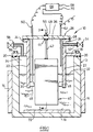
- FIG. 1 a cross section through a schematic diagram of a fluorine cell according to the present invention is shown generally at 10.
- the cell comprises a cell container 12 of mild steel construction, the cell container being cathodic.
- the cell container is provided with an electrical resistance heating jacket 14 for melting the electrolyte 16 within the cell.
- To the top of the cell container is fixed a sealing plate 18 which is insulated from the cathodic cell container by an insulating and sealing member 20.
- An electrically neutral skirt member 22 made of, in this case, Monel (Trade Mark) metal depends from the plate 18 and also extends upwardly therefrom to a flange member 24.
- a sealing lid member 26 is fixed to the flange 24 but is insulated therefrom by a sealing and insulating member 28, the lid 26 being anodic.
- the skirt member 22 extends downwardly and has its end 30 immersed in the electrolyte 16 so as to form two distinct chambers above the level 32 of the electrolyte; a cathode compartment in hydrogen chamber 34 and an anode compartment or fluorine gas chamber 36 which are separated from each other by the skirt member 22 and the electrolyte surface 32.
- anode Within the anode compartment 36 is an anode, shown generally at 40, and suspended from the sealing lid 26 by a flexible anode hanger 42 in the form of a mild steel rod which is welded 44 to the underside of the lid 26 (the construction of the anode 40 will be dealt with below in more detail with reference to Figure 2).
- the anode extends below the end 30 of the skirt member 22.
- Attached to the wall on the anode compartment 36 side of the skirt 22 are anode guide blocks 46 of fluoro-plastics material which maintain the anode 40 substantially central within the anode compartment 36 and prevent contact of the anode 40 with the skirt 22.
- anode connector stud 50 On the outer surface of the lid member is welded 48 an anode connector stud 50, thus, there is no through-hole provided in the lid member 26.
- an outlet conduit 52 In the upper portion of the fluorine chamber 36 is an outlet conduit 52 having a valve 54.
- a conduit 56 In the upper portion of the cathode compartment is a conduit 56 having a valve 58.
- Continuity sensor probes 60, 62 are provided to detect minimum and maximum heights of the electrolyte level 32, respectively.
- the probes are connected to a device 66 which starts and stops electrolysis in response to signals from the probes by providing a power supply indicated at 68,70 to the anode and cathode of the cell.
- a PTFE base layer 72 is fixed to the inner floor of the cell container 12 to prevent the generation of hydrogen gas beneath the anode compartment 36.
- the main anode body 80 comprises hard carbon in the form of a generally rectangular flat plate.
- the upper portion 82 of the anode body 80 is roughened by abrasion such as grit-blasting, for example.
- the roughened portion 82 is coated with pitch, in this case by dipping, but may be by brushing or spraying, and is allowed to cure/dry for 12 hours.
- the coated anode is then heated at 5-10°C/minute up to 500 to 650°C in a reducing atmosphere for 2 to 3 hours, followed by furnace cooling to ambient temperature.
- the cooled anode is then drilled and tapped and screwed 84 to a nickel hanger block 86 which has a flexible mild steel anode hanger rod 42 attached thereto.
- the coated upper portion 82 of the anode, the hanger block 86 and the lower portion of the flexible hanger rod 42 are then sprayed with a nickel coating 88 (the extend indicated by the line 90) by, for example, plasma-spraying.
- This method of anode preparation has been found to give excellent electrical contact, and is not susceptible to the corrosion problems of known anode constructions.
- the pitch was replaced with either Union Carbide UCAR (Trade mark) grade 34 graphite cement or a mixture of UCAR (Trade mark) graphite cement and crushed isotropic (non-graphitic) porous carbon having a density of 1.15 gcm -3 .
- UCAR Trade mark
- UCAR Trade mark
- crushed isotropic non-graphitic porous carbon having a density of 1.15 gcm -3 .
- the applied material was cured on the anode for 4 hours at 100°C followed by 16 hours at 130°C.
- the anodes were then fired in a hydrogen atmosphere for 30 minutes at 500°C followed by cooling to ambient temperature. Subsequent processing was as described as above.
- FIG. 5A to 5D show the main features of the cell according to the present invention and where various operating conditions are indicated schematically.
- the cell provides the ability to produce fluorine gas on demand.
- the device 66 is set at a current level in excess of that anticipated to supply the required fluorine gas generation rate.
- the end of the control probe 60 is below the surface level 32 of the hydrogen fluoride electrolyte 16.
- electrolysis is continued and fluorine gas is drawn off as required through the conduit 52 and valve 54.
- the apparatus may be constructed so as to produce fluorine at a relatively constant pressure by arranging for the depth of skirt penetration into the electrolyte to be at a precise level and for the height difference between the electrolyte in the anode and cathode compartments to be controlled by the depth setting of the probe 60.
- the cell is then run so that it is producing substantially more than the anticipated demand and the surface level 32 is effectively running constantly as shown in Figure 5B.
Landscapes
- Chemical & Material Sciences (AREA)
- Engineering & Computer Science (AREA)
- Chemical Kinetics & Catalysis (AREA)
- Electrochemistry (AREA)
- Materials Engineering (AREA)
- Metallurgy (AREA)
- Organic Chemistry (AREA)
- Inorganic Chemistry (AREA)
- Automation & Control Theory (AREA)
- Electrolytic Production Of Non-Metals, Compounds, Apparatuses Therefor (AREA)
- Hybrid Cells (AREA)
- Battery Electrode And Active Subsutance (AREA)
- Fuel Cell (AREA)
- Apparatus Associated With Microorganisms And Enzymes (AREA)
- Glass Compositions (AREA)
- Lubricants (AREA)
- Battery Mounting, Suspending (AREA)
- Primary Cells (AREA)
- Manufacture Of Macromolecular Shaped Articles (AREA)
- Insulated Conductors (AREA)
- Developing Agents For Electrophotography (AREA)
- Coating By Spraying Or Casting (AREA)
Claims (21)
- Cellule (10) de fluor pour la production de fluor, la cellule de fluor comprenant: un récipient de cellule (12) ayant un compartiment de cathode (34) et un compartiment d'anode, le compartiment d'anode comportant une anode (40), le compartiment de cathode et le compartiment d'anode ayant des moyens de séparation (22) entre eux, afin de séparer le gaz de fluor et le gaz d'hydrogène engendrés pendant le fonctionnement de ladite cellule de fluor, mais lesdits moyens de séparation permettant le passage d'un électrolyte (16) entre lesdits compartiments ; ladite anode s'étendant sous une extrémité inférieure (30) des moyens de séparation et étant continûment en contact avec l'électrolyte ; ladite cellule étant caractérisée par des moyens capteurs de contrôle (60, 62) dans au moins un desdits compartiments d'anode ou de cathode, pour capter le niveau (32) d'électrolyte dans ledit au moins un compartiment ; par des moyens d'alimentation de courant électrique (68, 70) aptes à répondre aux signaux provenant desdits moyens capteurs de contrôle, afin soit de démarrer, soit de couper l'alimentation en courant selon lesdits signaux.
- Cellule selon la revendication 1, caractérisée en ce que les moyens de séparation sont constitués d'un élément de jupe qui s'étend sur la surface (32) de l'électrolyte à l'intérieur de la cellule, de façon qu'il y soit réalisé deux compartiments séparés, un compartiment d'anode pour recevoir le fluor et un compartiment d'anode pour recevoir l'hydrogène ; au-dessus de la surface électrolyte.
- Cellule selon la revendication 2, caractérisée en ce que les compartiments au-dessus de la surface électrolyte sont fermés et présentent des moyens (52, 54, 56, 58) communiquant entre eux pour permettre soit au fluor soit à l'hydrogène en fonction des besoins, d'être ventilé ou extrait.
- Cellule selon l'une des revendications précédentes, caractérisée en ce qu'elle comporte en outre des moyens de chauffage (14) afin de permettre de chauffer l'électrolyte pour le placer à l'état fondu.
- Cellule selon l'une des revendications précédentes, caractérisée en ce que les moyens capteurs de contrôle comportent au moins un capteur (60, 62) destiné à commander un organe (66) qui commande l'électrolyse.
- Cellule selon l'une des revendications précédentes, caractérisée en ce que les moyens capteurs comportent une sonde (60) qui s'étend dans le compartiment d'anode (36) et produit un signal en réponse au niveau de la surface d'électrolyte (32).
- Cellule selon la revendication 6, caractérisée en ce que la sonde est choisie parmi le groupe comprenant des sondes de continuité électrique, des sondes de contact électrique ; des transducteurs de capacitance et des transducteurs optiques pour lire le niveau d'électrolyte.
- Cellule selon une des revendications précédentes, caractérisée en ce qu'elle est conçue pour produire du gaz à une pression présensiblement prédéterminée en vertu de la relation entre le réglage du capteur et la différence de hauteur de l'électrolyte dans le compartiment d'anode et dans le compartiment de cathode.
- Cellule selon une des revendications précédentes, caractérisée en ce que l'on prévoit des seconds moyens capteurs (62) pour détecter un niveau maximum de surface d'électrolyte dans le compartiment d'anode (36).
- Cellule selon la revendication 1, caractérisée en ce que les moyens capteurs sont situés dans le compartiment d'anode ou dans le compartiment de cathode, afin de lire le niveau de surface d'électrolyte.
- Cellule de fluor selon l'une des revendications précédentes, caractérisée en ce que ladite anode (40) comporte une partie (80) d'anode en carbone, ladite partie d'anode ayant une partie (86) d'accrochage métallique attachée par celle-ci par des moyens de fixation (84) et à revêtement de métal (88) appliqués sur au moins la zone dans la région de la jonction entre ladite partie d'anode et ladite partie d'accrochage.
- Cellule selon la revendication 11, caractérisée en ce que la partie (86) d'accrochage est attachée à la partie d'anodes (80) par des moyens mécaniques tels que des boulons ou des vis (84).
- Cellule selon les revendications 11 ou 12, caractérisée en ce que la zone de la jonction entre la partie d'accrochage et la partie d'anode est revêtue d'un métal (88) qui est sensiblement le même métal que celui de la partie d'accrochage.
- Cellule selon l'une des revendications 11 à 13, caractérisée en ce que la partie d'accrochage est réalisée en nickel ou un alliage à base de nickel.
- Cellule selon l'une des revendications 11 à 14, caractérisée en ce que le revêtement qui est appliqué à la jonction entre la partie d'anode et la partie d'accrochage est appliquée par une technique physique de dépôt par vapeur, telle que vaporisation à flamme ou plasma.
- Cellule selon l'une des revendications précédentes 11 à 15, caractérisée en ce qu'un traitement ultérieur est appliqué sur la région de la partie d'anode de carbone qui doit recevoir le revêtement de métal.
- Cellule de fluor selon l'une des revendications précédentes, et présentant une disposition de montage d'anode à l'intérieur du compartiment d'anodes, la disposition comprenant une partie d'anode (80) présentant des moyens d'accrochage flexibles (42) reliés à celles-ci, lesdits moyens flexibles d'accrochage étant reliés à une paroi (26) dudit compartiment d'anode afin de permettre le mouvement entre ladite anode (40) et les parois (22) dudit compartiment d'anode (36), et des membres de guidage isolants électriquement, interposés entre ladite anode et lesdites parois.
- Cellule comportant une disposition de montage d'anodes selon la revendication 17, caractérisée en ce que les moyens d'accrochage flexibles (42) sont reliés à une surface intérieure du compartiment d'anode par un procédé dans lequel aucun trou traversant n'est produit dans la paroi (26) du compartiment d'anode.
- Cellule comportant une disposition de montage d'anode selon la revendication 18, caractérisée en ce que le procédé de fixation est le soudage (44).
- Cellule comportant une disposition de montage d'anode selon l'une des revendications précédentes 17 à 19, caractérisée en ce que les membres de guidage isolant électriquement (46) comportent des matériaux fluoro-plastiques.
- Cellule présentant une disposition de montages d'anodes selon l'une des revendications précédentes 17 à 20, caractérisée en ce que l'élément de guidage (46) est attaché à la paroi ou aux parois du compartiment d'anode.
Priority Applications (2)
| Application Number | Priority Date | Filing Date | Title |
|---|---|---|---|
| EP99114648A EP0965661B1 (fr) | 1994-09-14 | 1995-09-11 | Dispositif de montage d'anode dans une cellule de production de fluor |
| EP98100057A EP0852267B1 (fr) | 1994-09-14 | 1995-09-11 | Cellule pour la production de fluor |
Applications Claiming Priority (3)
| Application Number | Priority Date | Filing Date | Title |
|---|---|---|---|
| GB9418598A GB9418598D0 (en) | 1994-09-14 | 1994-09-14 | Fluorine cell |
| GB9418598 | 1994-09-14 | ||
| PCT/GB1995/002145 WO1996008589A2 (fr) | 1994-09-14 | 1995-09-11 | Cellule de production de fluor |
Related Child Applications (2)
| Application Number | Title | Priority Date | Filing Date |
|---|---|---|---|
| EP99114648A Division EP0965661B1 (fr) | 1994-09-14 | 1995-09-11 | Dispositif de montage d'anode dans une cellule de production de fluor |
| EP98100057A Division EP0852267B1 (fr) | 1994-09-14 | 1995-09-11 | Cellule pour la production de fluor |
Publications (2)
| Publication Number | Publication Date |
|---|---|
| EP0728228A1 EP0728228A1 (fr) | 1996-08-28 |
| EP0728228B1 true EP0728228B1 (fr) | 2001-10-31 |
Family
ID=10761369
Family Applications (3)
| Application Number | Title | Priority Date | Filing Date |
|---|---|---|---|
| EP99114648A Expired - Lifetime EP0965661B1 (fr) | 1994-09-14 | 1995-09-11 | Dispositif de montage d'anode dans une cellule de production de fluor |
| EP95931296A Expired - Lifetime EP0728228B1 (fr) | 1994-09-14 | 1995-09-11 | Cellule de production de fluor |
| EP98100057A Expired - Lifetime EP0852267B1 (fr) | 1994-09-14 | 1995-09-11 | Cellule pour la production de fluor |
Family Applications Before (1)
| Application Number | Title | Priority Date | Filing Date |
|---|---|---|---|
| EP99114648A Expired - Lifetime EP0965661B1 (fr) | 1994-09-14 | 1995-09-11 | Dispositif de montage d'anode dans une cellule de production de fluor |
Family Applications After (1)
| Application Number | Title | Priority Date | Filing Date |
|---|---|---|---|
| EP98100057A Expired - Lifetime EP0852267B1 (fr) | 1994-09-14 | 1995-09-11 | Cellule pour la production de fluor |
Country Status (11)
| Country | Link |
|---|---|
| US (1) | US5688384A (fr) |
| EP (3) | EP0965661B1 (fr) |
| JP (1) | JP3769017B2 (fr) |
| KR (1) | KR100390139B1 (fr) |
| CN (1) | CN1137808A (fr) |
| AT (3) | ATE231932T1 (fr) |
| CA (3) | CA2221161A1 (fr) |
| DE (3) | DE69523560T2 (fr) |
| GB (1) | GB9418598D0 (fr) |
| WO (1) | WO1996008589A2 (fr) |
| ZA (1) | ZA957669B (fr) |
Cited By (2)
| Publication number | Priority date | Publication date | Assignee | Title |
|---|---|---|---|---|
| CN101949025A (zh) * | 2010-10-18 | 2011-01-19 | 天津市泰旭物流有限公司 | 一种采用电解合成法生产六氟化硫的技术 |
| WO2013092773A1 (fr) | 2011-12-22 | 2013-06-27 | Solvay Sa | Régulation du niveau de liquide dans une cellule électrolytique pour la génération de fluor |
Families Citing this family (36)
| Publication number | Priority date | Publication date | Assignee | Title |
|---|---|---|---|---|
| US6210549B1 (en) * | 1998-11-13 | 2001-04-03 | Larry A. Tharp | Fluorine gas generation system |
| WO2000051938A1 (fr) * | 1999-03-04 | 2000-09-08 | Surface Technology Systems Limited | Systeme generateur de gaz de trifluorure de chlore |
| KR100746384B1 (ko) * | 1999-03-04 | 2007-08-03 | 서페이스 테크놀로지 시스템스 피엘씨 | 기체발생장치 |
| FR2795817B1 (fr) * | 1999-07-02 | 2001-08-10 | Inst Francais Du Petrole | Sonde capacitive de mesure du niveau d'un liquide conducteur de l'electricite dans un recipient et procede de fabrication d'une telle sonde |
| US6500356B2 (en) * | 2000-03-27 | 2002-12-31 | Applied Materials, Inc. | Selectively etching silicon using fluorine without plasma |
| US20030010354A1 (en) * | 2000-03-27 | 2003-01-16 | Applied Materials, Inc. | Fluorine process for cleaning semiconductor process chamber |
| WO2001077412A1 (fr) * | 2000-04-07 | 2001-10-18 | Toyo Tanso Co., Ltd. | Appareil pour la production de fluor gazeux |
| US6843258B2 (en) * | 2000-12-19 | 2005-01-18 | Applied Materials, Inc. | On-site cleaning gas generation for process chamber cleaning |
| US20030098038A1 (en) * | 2001-11-26 | 2003-05-29 | Siegele Stephen H. | System and method for on-site generation and distribution of fluorine for fabrication processes |
| US20030121796A1 (en) * | 2001-11-26 | 2003-07-03 | Siegele Stephen H | Generation and distribution of molecular fluorine within a fabrication facility |
| US20040037768A1 (en) * | 2001-11-26 | 2004-02-26 | Robert Jackson | Method and system for on-site generation and distribution of a process gas |
| JP3725822B2 (ja) * | 2001-12-27 | 2005-12-14 | レール・リキード−ソシエテ・アノニム・ア・ディレクトワール・エ・コンセイユ・ドゥ・スールベイランス・プール・レテュード・エ・レクスプロワタシオン・デ・プロセデ・ジョルジュ・クロード | フッ素ガス生成及び供給装置 |
| KR100519843B1 (ko) | 2002-05-29 | 2005-10-06 | 도요탄소 가부시키가이샤 | 불소가스 발생장치 |
| GB0215697D0 (en) * | 2002-07-06 | 2002-08-14 | Boc Group Plc | Fluorine cell |
| JP3905433B2 (ja) * | 2002-07-11 | 2007-04-18 | レール・リキード−ソシエテ・アノニム・ア・ディレクトワール・エ・コンセイユ・ドゥ・スールベイランス・プール・レテュード・エ・レクスプロワタシオン・デ・プロセデ・ジョルジュ・クロード | フッ素ガス生成装置 |
| KR101089623B1 (ko) * | 2002-10-04 | 2011-12-06 | 더 리전츠 오브 더 유니버시티 오브 캘리포니아 | 불소 분리 및 발생 장치 |
| KR100533411B1 (ko) | 2002-11-08 | 2005-12-02 | 도요탄소 가부시키가이샤 | 불소가스 발생장치와 그 전해욕 액면 제어방법 |
| JP3527735B1 (ja) | 2002-11-20 | 2004-05-17 | 東洋炭素株式会社 | フッ素ガス発生装置 |
| JP3725145B2 (ja) | 2003-07-14 | 2005-12-07 | 東洋炭素株式会社 | 溶融塩電解浴の制御装置及びその制御方法 |
| EP1880043A4 (fr) * | 2005-04-15 | 2009-06-03 | Innovative Hydrogen Solutions | Cellule electrolytique pour moteur a combustion interne |
| JP4777989B2 (ja) | 2005-08-25 | 2011-09-21 | 東洋炭素株式会社 | フッ素系ガス発生装置 |
| US20070074743A1 (en) * | 2005-10-04 | 2007-04-05 | Mcfarlane Graham | H2 conditioning of chamber following cleaning cycle |
| CN101213325B (zh) | 2006-01-20 | 2010-09-22 | 东洋炭素株式会社 | 制造氟或三氟化氮的电解装置 |
| JP5567375B2 (ja) * | 2010-04-14 | 2014-08-06 | 東洋炭素株式会社 | 気体発生装置および気体発生方法 |
| CN101949024A (zh) * | 2010-10-18 | 2011-01-19 | 天津市泰旭物流有限公司 | 电解氟化钾一氟化氢制备氟气的技术 |
| TWI551730B (zh) * | 2010-11-17 | 2016-10-01 | 首威公司 | 電解器設備 |
| JP5824256B2 (ja) * | 2011-06-29 | 2015-11-25 | 東洋炭素株式会社 | 電解装置 |
| CN102337491A (zh) * | 2011-10-28 | 2012-02-01 | 核工业理化工程研究院华核新技术开发公司 | 制氟用碳阳极的热喷涂处理方法 |
| WO2014037485A1 (fr) * | 2012-09-10 | 2014-03-13 | Solvay Sa | Procédé de nettoyage de chambre utilisant f2 et processus de fabrication de f2 pour ce procédé |
| CN106637284B (zh) * | 2016-12-28 | 2018-07-06 | 中核四0四有限公司 | 一种中温电解制氟用炭阳极板螺孔浸渍方法及装置 |
| CN107201530A (zh) * | 2017-05-10 | 2017-09-26 | 东北大学 | 一种碱土金属氯化物溶液隔膜电解制备氢氧化物的方法 |
| KR102258314B1 (ko) * | 2017-06-30 | 2021-06-01 | 쇼와 덴코 가부시키가이샤 | 불소 전해조 양극 설치부, 불소 전해조 및 불소 가스의 제조 방법 |
| JP7428126B2 (ja) * | 2018-08-03 | 2024-02-06 | 株式会社レゾナック | 電解合成用陽極、及び、フッ素ガス又は含フッ素化合物の製造方法 |
| WO2020085066A1 (fr) * | 2018-10-24 | 2020-04-30 | 昭和電工株式会社 | Dispositif de production de gaz fluoré |
| CN111005032A (zh) * | 2019-12-26 | 2020-04-14 | 福建德尔科技有限公司 | 一种便携式全自动高纯氟气生产装置系统 |
| US20230332305A1 (en) * | 2020-09-08 | 2023-10-19 | Versum Materials Us, Llc | Electrode attachment assembly, cell and method of use |
Family Cites Families (10)
| Publication number | Priority date | Publication date | Assignee | Title |
|---|---|---|---|---|
| US3616436A (en) * | 1967-06-13 | 1971-10-26 | Georg Haas | Oxygen stream dispenser |
| NL170314C (nl) * | 1970-06-01 | 1982-10-18 | Montedison Spa | Electrolysecel voor de bereiding van fluor. |
| US4002552A (en) * | 1975-09-19 | 1977-01-11 | Trienco, Inc. | Liquid level control system |
| FR2349667A1 (fr) * | 1976-04-26 | 1977-11-25 | Solvay | Cellule d'electrolyse a diaphragme |
| GB2135334A (en) * | 1983-02-24 | 1984-08-30 | British Nuclear Fuels Plc | Composite carbon electrode |
| US5037518A (en) * | 1989-09-08 | 1991-08-06 | Packard Instrument Company | Apparatus and method for generating hydrogen and oxygen by electrolytic dissociation of water |
| DE69018761T2 (de) * | 1989-10-26 | 1995-12-07 | Mitsui Toatsu Chemicals | Methode zur Herstellung von Stickstofftrifluorid. |
| JPH03232988A (ja) * | 1990-02-06 | 1991-10-16 | Toyo Tanso Kk | 炭素電極ならびにそれを用いるhf含有溶融塩の電解方法及び装置 |
| US5154813A (en) * | 1991-06-10 | 1992-10-13 | Dill Raymond J | Protective coating of stub ends in anode assemblies |
| CA2071235C (fr) * | 1991-07-26 | 2004-10-19 | Gerald L. Bauer | Anode pour cellule electrolytique utilisee pour la preparation du fluor |
-
1994
- 1994-09-14 GB GB9418598A patent/GB9418598D0/en active Pending
-
1995
- 1995-09-11 CA CA002221161A patent/CA2221161A1/fr not_active Abandoned
- 1995-09-11 EP EP99114648A patent/EP0965661B1/fr not_active Expired - Lifetime
- 1995-09-11 AT AT98100057T patent/ATE231932T1/de not_active IP Right Cessation
- 1995-09-11 CA CA002238142A patent/CA2238142A1/fr not_active Abandoned
- 1995-09-11 US US08/624,409 patent/US5688384A/en not_active Expired - Lifetime
- 1995-09-11 AT AT95931296T patent/ATE207980T1/de active
- 1995-09-11 DE DE69523560T patent/DE69523560T2/de not_active Expired - Lifetime
- 1995-09-11 EP EP95931296A patent/EP0728228B1/fr not_active Expired - Lifetime
- 1995-09-11 CA CA002174520A patent/CA2174520C/fr not_active Expired - Fee Related
- 1995-09-11 JP JP50998896A patent/JP3769017B2/ja not_active Expired - Lifetime
- 1995-09-11 KR KR1019960702456A patent/KR100390139B1/ko not_active IP Right Cessation
- 1995-09-11 AT AT99114648T patent/ATE220734T1/de not_active IP Right Cessation
- 1995-09-11 DE DE69529537T patent/DE69529537T2/de not_active Expired - Lifetime
- 1995-09-11 EP EP98100057A patent/EP0852267B1/fr not_active Expired - Lifetime
- 1995-09-11 WO PCT/GB1995/002145 patent/WO1996008589A2/fr active IP Right Grant
- 1995-09-11 DE DE69527446T patent/DE69527446T2/de not_active Expired - Lifetime
- 1995-09-11 CN CN95190885A patent/CN1137808A/zh active Pending
- 1995-09-13 ZA ZA957669A patent/ZA957669B/xx unknown
Cited By (2)
| Publication number | Priority date | Publication date | Assignee | Title |
|---|---|---|---|---|
| CN101949025A (zh) * | 2010-10-18 | 2011-01-19 | 天津市泰旭物流有限公司 | 一种采用电解合成法生产六氟化硫的技术 |
| WO2013092773A1 (fr) | 2011-12-22 | 2013-06-27 | Solvay Sa | Régulation du niveau de liquide dans une cellule électrolytique pour la génération de fluor |
Also Published As
| Publication number | Publication date |
|---|---|
| US5688384A (en) | 1997-11-18 |
| ZA957669B (en) | 1996-04-15 |
| EP0852267A2 (fr) | 1998-07-08 |
| DE69527446D1 (de) | 2002-08-22 |
| WO1996008589A3 (fr) | 1996-09-26 |
| ATE231932T1 (de) | 2003-02-15 |
| JP3769017B2 (ja) | 2006-04-19 |
| DE69523560T2 (de) | 2002-07-18 |
| EP0852267A3 (fr) | 1998-09-30 |
| DE69527446T2 (de) | 2003-01-23 |
| EP0965661B1 (fr) | 2002-07-17 |
| EP0965661A2 (fr) | 1999-12-22 |
| CA2174520C (fr) | 1999-07-06 |
| EP0965661A3 (fr) | 2000-01-19 |
| EP0728228A1 (fr) | 1996-08-28 |
| WO1996008589A2 (fr) | 1996-03-21 |
| EP0852267B1 (fr) | 2003-01-29 |
| JPH09505853A (ja) | 1997-06-10 |
| ATE207980T1 (de) | 2001-11-15 |
| CA2174520A1 (fr) | 1996-03-21 |
| KR960705961A (ko) | 1996-11-08 |
| DE69529537T2 (de) | 2003-11-06 |
| CN1137808A (zh) | 1996-12-11 |
| ATE220734T1 (de) | 2002-08-15 |
| DE69523560D1 (en) | 2001-12-06 |
| CA2221161A1 (fr) | 1996-03-21 |
| CA2238142A1 (fr) | 1996-03-21 |
| DE69529537D1 (de) | 2003-03-06 |
| KR100390139B1 (ko) | 2003-11-17 |
| GB9418598D0 (en) | 1994-11-02 |
Similar Documents
| Publication | Publication Date | Title |
|---|---|---|
| EP0728228B1 (fr) | Cellule de production de fluor | |
| US4379043A (en) | Water-decomposition and gas-generating apparatus | |
| US20080128270A1 (en) | Electrolytic apparatus for molten salt | |
| JP2009215578A (ja) | フッ素電解装置 | |
| AU2021255398B2 (en) | Electrolysis system and method of using same | |
| US4247381A (en) | Facility for conducting electrical power to electrodes | |
| KR100533411B1 (ko) | 불소가스 발생장치와 그 전해욕 액면 제어방법 | |
| KR100579385B1 (ko) | 용융염 전해욕의 제어 장치와 그 제어 방법 | |
| US2502888A (en) | Electrolytic cell | |
| JP7318658B2 (ja) | フッ素ガス製造装置 | |
| US3203882A (en) | Method of operating an alkali chlorate cell | |
| SU587874A3 (ru) | Устройство дл подвода электрического тока | |
| CN113737225A (zh) | 一种内衬结构及采用该内衬结构的稀土金属熔盐电解槽 | |
| US3745106A (en) | Fluid sheathed electrode lead for use in a corrosive environment | |
| GB2135334A (en) | Composite carbon electrode | |
| GB2135335A (en) | Supports for carbon electrodes | |
| CN212059846U (zh) | 一种自动补液阴极剥离试验装置 | |
| US3274082A (en) | Gas removal from electrolytic cells | |
| JPH02144856A (ja) | 溶融炭酸塩型燃料電池 | |
| IT202100001781A1 (it) | Reattore plasma-elettrolitico generatore di vapore saturo alimentato con acqua salata e tensione 230vdc | |
| Bauer et al. | Improvements in Fluorine Generation | |
| KR20040082455A (ko) | 대용량 브라운가스 발생장치 | |
| Holleck et al. | THE REDUCTION OF CHLORINE! ON CARBON IN |
Legal Events
| Date | Code | Title | Description |
|---|---|---|---|
| PUAI | Public reference made under article 153(3) epc to a published international application that has entered the european phase |
Free format text: ORIGINAL CODE: 0009012 |
|
| AK | Designated contracting states |
Kind code of ref document: A1 Designated state(s): AT BE CH DE DK ES FR GB GR IE IT LI LU MC NL PT SE |
|
| 17P | Request for examination filed |
Effective date: 19960912 |
|
| 17Q | First examination report despatched |
Effective date: 19970912 |
|
| GRAG | Despatch of communication of intention to grant |
Free format text: ORIGINAL CODE: EPIDOS AGRA |
|
| RIC1 | Information provided on ipc code assigned before grant |
Free format text: 7C 25B 9/00 A, 7C 25B 1/24 B, 7C 25B 15/02 B, 7C 25B 11/12 B |
|
| GRAG | Despatch of communication of intention to grant |
Free format text: ORIGINAL CODE: EPIDOS AGRA |
|
| GRAG | Despatch of communication of intention to grant |
Free format text: ORIGINAL CODE: EPIDOS AGRA |
|
| GRAH | Despatch of communication of intention to grant a patent |
Free format text: ORIGINAL CODE: EPIDOS IGRA |
|
| GRAH | Despatch of communication of intention to grant a patent |
Free format text: ORIGINAL CODE: EPIDOS IGRA |
|
| GRAA | (expected) grant |
Free format text: ORIGINAL CODE: 0009210 |
|
| AK | Designated contracting states |
Kind code of ref document: B1 Designated state(s): AT BE CH DE DK ES FR GB GR IE IT LI LU MC NL PT SE |
|
| PG25 | Lapsed in a contracting state [announced via postgrant information from national office to epo] |
Ref country code: NL Free format text: LAPSE BECAUSE OF FAILURE TO SUBMIT A TRANSLATION OF THE DESCRIPTION OR TO PAY THE FEE WITHIN THE PRESCRIBED TIME-LIMIT Effective date: 20011031 Ref country code: LI Free format text: LAPSE BECAUSE OF FAILURE TO SUBMIT A TRANSLATION OF THE DESCRIPTION OR TO PAY THE FEE WITHIN THE PRESCRIBED TIME-LIMIT Effective date: 20011031 Ref country code: CH Free format text: LAPSE BECAUSE OF FAILURE TO SUBMIT A TRANSLATION OF THE DESCRIPTION OR TO PAY THE FEE WITHIN THE PRESCRIBED TIME-LIMIT Effective date: 20011031 Ref country code: BE Free format text: LAPSE BECAUSE OF FAILURE TO SUBMIT A TRANSLATION OF THE DESCRIPTION OR TO PAY THE FEE WITHIN THE PRESCRIBED TIME-LIMIT Effective date: 20011031 Ref country code: AT Free format text: LAPSE BECAUSE OF FAILURE TO SUBMIT A TRANSLATION OF THE DESCRIPTION OR TO PAY THE FEE WITHIN THE PRESCRIBED TIME-LIMIT Effective date: 20011031 |
|
| REF | Corresponds to: |
Ref document number: 207980 Country of ref document: AT Date of ref document: 20011115 Kind code of ref document: T |
|
| REG | Reference to a national code |
Ref country code: CH Ref legal event code: EP |
|
| REF | Corresponds to: |
Ref document number: 69523560 Country of ref document: DE Date of ref document: 20011206 |
|
| REG | Reference to a national code |
Ref country code: IE Ref legal event code: FG4D |
|
| REG | Reference to a national code |
Ref country code: GB Ref legal event code: IF02 |
|
| PG25 | Lapsed in a contracting state [announced via postgrant information from national office to epo] |
Ref country code: SE Free format text: LAPSE BECAUSE OF FAILURE TO SUBMIT A TRANSLATION OF THE DESCRIPTION OR TO PAY THE FEE WITHIN THE PRESCRIBED TIME-LIMIT Effective date: 20020131 Ref country code: PT Free format text: LAPSE BECAUSE OF FAILURE TO SUBMIT A TRANSLATION OF THE DESCRIPTION OR TO PAY THE FEE WITHIN THE PRESCRIBED TIME-LIMIT Effective date: 20020131 Ref country code: DK Free format text: LAPSE BECAUSE OF FAILURE TO SUBMIT A TRANSLATION OF THE DESCRIPTION OR TO PAY THE FEE WITHIN THE PRESCRIBED TIME-LIMIT Effective date: 20020131 |
|
| PG25 | Lapsed in a contracting state [announced via postgrant information from national office to epo] |
Ref country code: GR Free format text: LAPSE BECAUSE OF FAILURE TO SUBMIT A TRANSLATION OF THE DESCRIPTION OR TO PAY THE FEE WITHIN THE PRESCRIBED TIME-LIMIT Effective date: 20020201 |
|
| NLV1 | Nl: lapsed or annulled due to failure to fulfill the requirements of art. 29p and 29m of the patents act | ||
| PG25 | Lapsed in a contracting state [announced via postgrant information from national office to epo] |
Ref country code: ES Free format text: LAPSE BECAUSE OF FAILURE TO SUBMIT A TRANSLATION OF THE DESCRIPTION OR TO PAY THE FEE WITHIN THE PRESCRIBED TIME-LIMIT Effective date: 20020430 |
|
| REG | Reference to a national code |
Ref country code: CH Ref legal event code: PL |
|
| PLBE | No opposition filed within time limit |
Free format text: ORIGINAL CODE: 0009261 |
|
| STAA | Information on the status of an ep patent application or granted ep patent |
Free format text: STATUS: NO OPPOSITION FILED WITHIN TIME LIMIT |
|
| PG25 | Lapsed in a contracting state [announced via postgrant information from national office to epo] |
Ref country code: LU Free format text: LAPSE BECAUSE OF NON-PAYMENT OF DUE FEES Effective date: 20020911 Ref country code: IE Free format text: LAPSE BECAUSE OF NON-PAYMENT OF DUE FEES Effective date: 20020911 |
|
| 26N | No opposition filed | ||
| PG25 | Lapsed in a contracting state [announced via postgrant information from national office to epo] |
Ref country code: MC Free format text: LAPSE BECAUSE OF NON-PAYMENT OF DUE FEES Effective date: 20030401 |
|
| REG | Reference to a national code |
Ref country code: IE Ref legal event code: MM4A |
|
| PGFP | Annual fee paid to national office [announced via postgrant information from national office to epo] |
Ref country code: IT Payment date: 20060930 Year of fee payment: 12 |
|
| REG | Reference to a national code |
Ref country code: GB Ref legal event code: 732E |
|
| REG | Reference to a national code |
Ref country code: GB Ref legal event code: 732E |
|
| REG | Reference to a national code |
Ref country code: FR Ref legal event code: TP Ref country code: FR Ref legal event code: CD |
|
| REG | Reference to a national code |
Ref country code: FR Ref legal event code: TP |
|
| PG25 | Lapsed in a contracting state [announced via postgrant information from national office to epo] |
Ref country code: IT Free format text: LAPSE BECAUSE OF NON-PAYMENT OF DUE FEES Effective date: 20070911 |
|
| PGFP | Annual fee paid to national office [announced via postgrant information from national office to epo] |
Ref country code: DE Payment date: 20140903 Year of fee payment: 20 |
|
| PGFP | Annual fee paid to national office [announced via postgrant information from national office to epo] |
Ref country code: GB Payment date: 20140910 Year of fee payment: 20 |
|
| PGFP | Annual fee paid to national office [announced via postgrant information from national office to epo] |
Ref country code: FR Payment date: 20140906 Year of fee payment: 20 |
|
| REG | Reference to a national code |
Ref country code: DE Ref legal event code: R071 Ref document number: 69523560 Country of ref document: DE |
|
| REG | Reference to a national code |
Ref country code: GB Ref legal event code: PE20 Expiry date: 20150910 |
|
| PG25 | Lapsed in a contracting state [announced via postgrant information from national office to epo] |
Ref country code: GB Free format text: LAPSE BECAUSE OF EXPIRATION OF PROTECTION Effective date: 20150910 |