EP0726825B1 - Verfahren zur herstellung eines pleuels aus blech - Google Patents
Verfahren zur herstellung eines pleuels aus blech Download PDFInfo
- Publication number
- EP0726825B1 EP0726825B1 EP94931548A EP94931548A EP0726825B1 EP 0726825 B1 EP0726825 B1 EP 0726825B1 EP 94931548 A EP94931548 A EP 94931548A EP 94931548 A EP94931548 A EP 94931548A EP 0726825 B1 EP0726825 B1 EP 0726825B1
- Authority
- EP
- European Patent Office
- Prior art keywords
- rod
- connecting rod
- sheet
- bearing
- bent
- Prior art date
- Legal status (The legal status is an assumption and is not a legal conclusion. Google has not performed a legal analysis and makes no representation as to the accuracy of the status listed.)
- Expired - Lifetime
Links
- 229910052751 metal Inorganic materials 0.000 title claims abstract description 51
- 239000002184 metal Substances 0.000 title claims abstract description 51
- 238000000034 method Methods 0.000 title claims description 13
- 238000004519 manufacturing process Methods 0.000 title description 9
- 230000008569 process Effects 0.000 title description 7
- 125000006850 spacer group Chemical group 0.000 claims description 5
- 238000010438 heat treatment Methods 0.000 claims description 2
- 230000002093 peripheral effect Effects 0.000 claims 4
- 230000008901 benefit Effects 0.000 description 4
- 230000007246 mechanism Effects 0.000 description 3
- 238000005452 bending Methods 0.000 description 2
- 238000005242 forging Methods 0.000 description 2
- 238000009434 installation Methods 0.000 description 2
- 229910000831 Steel Inorganic materials 0.000 description 1
- RTAQQCXQSZGOHL-UHFFFAOYSA-N Titanium Chemical compound [Ti] RTAQQCXQSZGOHL-UHFFFAOYSA-N 0.000 description 1
- 210000000078 claw Anatomy 0.000 description 1
- 230000000593 degrading effect Effects 0.000 description 1
- 238000013461 design Methods 0.000 description 1
- 238000009826 distribution Methods 0.000 description 1
- 230000005489 elastic deformation Effects 0.000 description 1
- 238000003754 machining Methods 0.000 description 1
- 239000000463 material Substances 0.000 description 1
- 238000012986 modification Methods 0.000 description 1
- 230000004048 modification Effects 0.000 description 1
- 238000000926 separation method Methods 0.000 description 1
- 238000007493 shaping process Methods 0.000 description 1
- 230000035939 shock Effects 0.000 description 1
- 239000010959 steel Substances 0.000 description 1
- 238000005496 tempering Methods 0.000 description 1
- 239000010936 titanium Substances 0.000 description 1
- 229910052719 titanium Inorganic materials 0.000 description 1
- 238000012549 training Methods 0.000 description 1
- 238000012546 transfer Methods 0.000 description 1
- 230000007704 transition Effects 0.000 description 1
- 238000005303 weighing Methods 0.000 description 1
Images


Classifications
-
- F—MECHANICAL ENGINEERING; LIGHTING; HEATING; WEAPONS; BLASTING
- F16—ENGINEERING ELEMENTS AND UNITS; GENERAL MEASURES FOR PRODUCING AND MAINTAINING EFFECTIVE FUNCTIONING OF MACHINES OR INSTALLATIONS; THERMAL INSULATION IN GENERAL
- F16C—SHAFTS; FLEXIBLE SHAFTS; ELEMENTS OR CRANKSHAFT MECHANISMS; ROTARY BODIES OTHER THAN GEARING ELEMENTS; BEARINGS
- F16C7/00—Connecting-rods or like links pivoted at both ends; Construction of connecting-rod heads
- F16C7/02—Constructions of connecting-rods with constant length
- F16C7/023—Constructions of connecting-rods with constant length for piston engines, pumps or the like
-
- B—PERFORMING OPERATIONS; TRANSPORTING
- B21—MECHANICAL METAL-WORKING WITHOUT ESSENTIALLY REMOVING MATERIAL; PUNCHING METAL
- B21D—WORKING OR PROCESSING OF SHEET METAL OR METAL TUBES, RODS OR PROFILES WITHOUT ESSENTIALLY REMOVING MATERIAL; PUNCHING METAL
- B21D53/00—Making other particular articles
- B21D53/84—Making other particular articles other parts for engines, e.g. connecting-rods
-
- F—MECHANICAL ENGINEERING; LIGHTING; HEATING; WEAPONS; BLASTING
- F16—ENGINEERING ELEMENTS AND UNITS; GENERAL MEASURES FOR PRODUCING AND MAINTAINING EFFECTIVE FUNCTIONING OF MACHINES OR INSTALLATIONS; THERMAL INSULATION IN GENERAL
- F16C—SHAFTS; FLEXIBLE SHAFTS; ELEMENTS OR CRANKSHAFT MECHANISMS; ROTARY BODIES OTHER THAN GEARING ELEMENTS; BEARINGS
- F16C7/00—Connecting-rods or like links pivoted at both ends; Construction of connecting-rod heads
- F16C7/08—Connecting-rods or like links pivoted at both ends; Construction of connecting-rod heads made from sheet metal
-
- Y—GENERAL TAGGING OF NEW TECHNOLOGICAL DEVELOPMENTS; GENERAL TAGGING OF CROSS-SECTIONAL TECHNOLOGIES SPANNING OVER SEVERAL SECTIONS OF THE IPC; TECHNICAL SUBJECTS COVERED BY FORMER USPC CROSS-REFERENCE ART COLLECTIONS [XRACs] AND DIGESTS
- Y10—TECHNICAL SUBJECTS COVERED BY FORMER USPC
- Y10T—TECHNICAL SUBJECTS COVERED BY FORMER US CLASSIFICATION
- Y10T29/00—Metal working
- Y10T29/49—Method of mechanical manufacture
- Y10T29/49229—Prime mover or fluid pump making
- Y10T29/49288—Connecting rod making
- Y10T29/49291—Connecting rod making including metal forging or die shaping
-
- Y—GENERAL TAGGING OF NEW TECHNOLOGICAL DEVELOPMENTS; GENERAL TAGGING OF CROSS-SECTIONAL TECHNOLOGIES SPANNING OVER SEVERAL SECTIONS OF THE IPC; TECHNICAL SUBJECTS COVERED BY FORMER USPC CROSS-REFERENCE ART COLLECTIONS [XRACs] AND DIGESTS
- Y10—TECHNICAL SUBJECTS COVERED BY FORMER USPC
- Y10T—TECHNICAL SUBJECTS COVERED BY FORMER US CLASSIFICATION
- Y10T74/00—Machine element or mechanism
- Y10T74/21—Elements
- Y10T74/2142—Pitmans and connecting rods
- Y10T74/2153—Sheet metal type
-
- Y—GENERAL TAGGING OF NEW TECHNOLOGICAL DEVELOPMENTS; GENERAL TAGGING OF CROSS-SECTIONAL TECHNOLOGIES SPANNING OVER SEVERAL SECTIONS OF THE IPC; TECHNICAL SUBJECTS COVERED BY FORMER USPC CROSS-REFERENCE ART COLLECTIONS [XRACs] AND DIGESTS
- Y10—TECHNICAL SUBJECTS COVERED BY FORMER USPC
- Y10T—TECHNICAL SUBJECTS COVERED BY FORMER US CLASSIFICATION
- Y10T74/00—Machine element or mechanism
- Y10T74/21—Elements
- Y10T74/2142—Pitmans and connecting rods
- Y10T74/2162—Engine type
Definitions
- the invention is concerned with a method of manufacture a one-piece or multi-piece connecting rod with a connecting rod eye, Connecting rod shaft and a connecting rod head made of at least one Sheet metal strip that is essentially vertical on both sides angled bridges shaped and normal to his Main level to cylindrical or semi-cylindrical wings around the bearing axles of the connecting rod head and / or the connecting rod eye is bent, after which all sheet metal parts, which parting lines in the wings of the connecting rod, in the immediate Be fixed near the wings.
- the invention is concerned continue with a connecting rod made of sheet metal the preamble of claim 3.
- Connecting rods - also called connecting rods - are mostly used today in the Forging process manufactured. Have forged connecting rods a relatively high weight, which balances the mass of the crank mechanism difficult. This problem of mass balancing is further increased by the fact that the connecting rods are in their finished weights subject to strong fluctuations, catches that the connecting rods are weighed individually and then sorted in the crank mechanism. When using one-piece crankshafts are connecting rods with split connecting rod heads required. This means that the forged connecting rod separated at the connecting rod head and then with the difficulties the exact centering can be reassembled got to. Overall, the forging process for connecting rod manufacturing complex and expensive.
- Titanium connecting rods are also known, although with excellent Strength properties come up, but in their Manufacturing are very expensive. Therefore, they are preferred in Small series used for the highest demands.
- the object of the invention is a method of the beginning to create the type mentioned, which is easy and leads at the same time to the rigid connecting rod and, if necessary, Manufacture of a multi-part connecting rod without difficulty and subsequent splitting allowed.
- the object is achieved in that a only sheet metal part forming the connecting rod shaft on his one end cylindrical around the bearing axis of the connecting rod eye and at its other end semi-cylindrical or cylindrical is bent around the bearing axis of the connecting rod head.
- a connecting rod according to the invention is defined in claim 3.
- the sheet metal parts can be fixed with screws, joints or Terminal connections are made, the connection of the divided Conrod head released after fine machining must be to the connecting rod on the crankshaft journal final assembly.
- the between the wings and the Crank journals to be arranged are included anchored to them in the dividing joints.
- a bearing bush is clamped in the connecting rod eye picks up the piston pin.
- screw connections are used, they are preferred between screw head and connecting rod and / or between nut and connecting rods each provided spacers so that long Screws can be used to clamp the sheet metal parts.
- vibration and shock-loaded screw connections have the advantage that they a higher shape-changing capacity even in the pre-tensioned state own and so are able to withstand voltage spikes degrading through elastic deformation, which increases the load of the screw shaft reduced.
- edge webs of the sheet metal strip can, if space restrictions make this necessary, flattened or in places be completely removed. This is conveniently done before bending the sheet metal strip, as this this is simplified.
- vibration dampers must be provided between them.
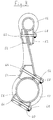
- a connecting rod 10 shown in Fig. 1 consists of two sheet metal parts 12, 14 with vertically angled edge webs 16, 17.
- the upper sheet metal strip 12 became normal to its main plane 18 at one end to a cylindrical wing 20 around the bearing axis of the connecting rod eye and at its other end to a semi-cylindrical wing 22 around the bearing axis of the connecting rod head bent.
- a graphic breakout in the Connecting rod shaft clarifies the structure of sheet metal connecting rod 10 in a U shape.
- the lower sheet metal part 14 became normal to its main plane 24 to a connecting rod bearing cover with a semi-cylindrical wing 26 shaped. Due to the division occur between the wings 22, 26 of the upper sheet metal part 12 and the lower Sheet metal part 14 division joints 28, 30. In the field of Gaps 28, 30 are the sheet metal parts 12, 14 with the Wings 22, 26 provided radially lying mounting surfaces. The actual attachment takes place in the lower area Gap 28 via a bracket 32, which as the Fastening tabs formed ends 33, 35 of the sheet metal parts 12, 14 compresses. At the upper parting joint 30 of the connecting rod head the two sheet metal parts are braced with Using a screw 34 and a nut (not shown).
- wing 20 of the connecting rod eye also a parting line 36
- a fastening of the bounding Pieces of sheet metal necessary.
- Fig. 1 are here on the edge webs 16 of the upper Sheet metal part 12 brackets 38 so that they bend open prevent the connecting rod eye.
- the bridges can go to this Purpose with serrations, corrugations or projections be to ensure a claw with the clips 38.
- connecting elements 32, 34, 38 near the wing are the connecting elements 32, 34, 38 near the wing arranged.
- the connecting rod 10 is suitable for one-piece crankshafts.
- a one-piece embodiment of the connecting rod 10, not shown is particularly suitable for crankshafts with freely accessible Bearing journal.
- FIG. 2 shows the connecting rod 10 according to FIG. 1 with spacers 50, 52, 54, 56, 58, 60, the use of long clamping screws 62, 64, 66 enable.
- the spacers are essentially formed as a U-shaped sheet metal bracket, the edges of the lateral bars of the sheet metal bracket to match the respective installation position are shaped so that they are in their full length rest on the connecting rod and as a support for the screw heads or associated nuts 68 provided base areas two opposite sheet metal angles in assembled Condition are parallel to the surface. This geometry is from FIG. 3 evident.
- the holes in the base of the sheet metal angle must also with the associated holes in the body of the connecting rod are aligned so that the screws do not during installation tilt.
Landscapes
- Engineering & Computer Science (AREA)
- General Engineering & Computer Science (AREA)
- Mechanical Engineering (AREA)
- Shafts, Cranks, Connecting Bars, And Related Bearings (AREA)
Description
- Fig. 1
- ein Pleuel aus zwei Blechstreifen mit geteilten Pleuelkopf;
- Fig. 2
- ein Pleuel nach Fig. 1 mit Abstandhaltern und langen Spannschrauben;
- Fig. 3
- einen Längsschnitt des Pleuels nach Fig. 2.
Claims (10)
- Verfahren zur Herstellung eines ein- oder mehrteiligen Pleuels (10) mit einem Pleuelauge, Pleuelschaft und einem Pleuelkopf aus wenigstens einem Blechstreifen, der beidseitig mit im wesentlichen senkrecht abgewinkelten Randstegen (16, 17) geformt und normal zu seiner Hauptebene (18, 24) zu zylindrischen oder halbzylindrischen Tragflächen (20, 22, 26) um die Lagerachsen des Pleuelkopfes und/oder des Pleuelauges gebogen wird, wonach alle Blechteile, welche Teilungsfugen (28, 30, 36) in den Tragflächen des Pleuels (10) bilden, in unmittelbarer Nähe der Tragflächen fixiert werden, dadurch gekennzeichnet, daß ein einziges den Pleuelschaft bildendes Blechteil an seinem einen Ende zylindrisch um die Lagerachse des Pleuelauges und an seinem anderen Ende halbzylindrisch oder zylindrisch um die Lagerachse des Pleuelkopfes gebogen wird.
- Verfahren nach Anspruch 1, dadurch gekennzeichnet, daß nach dem Formen und ggf. einer Wärmebehandlung die die Teilungsfugen (28, 30, 36) der Tragflächen (20, 22, 26) bildenden Blechteile vorläufig fixiert und die Tragflächen feinbearbeitet werden.
- Nach einem Verfahren nach Anspruch 1 hergestelltes Pleuel (10) aus Blech mit einem Pleuelschaft, einem Pleuelauge und einem Pleuelkopf, das aus wenigstens einem in seiner Hauptebene (18, 24) parallel zu den Lagerachsen des Pleuelauges und -kopfes liegenden Blechteil mit beidseitig senkrecht abgewinkelten Randstegen besteht und alle Blechteile, welche Teilungsfugen (28, 30, 36) in den Tragflächen (20, 22, 26) des Pleuels (10) bilden, in unmittelbarer Nähe der Tragflächen (20, 22, 26) fixierbar sind, dadurch gekennzeichnet, daß ein einziges den Pleuelschaft bildendes Blechteil an seinem einen Ende zylindrisch um die Lagerachse des Pleuelauges und an seinem anderen Ende halbzylindrisch oder zylindrisch um die Lagerachse des Pleuelkopfes gebogen ist.
- Pleuel nach Anspruch 3, dadurch gekennzeichnet, daß der Pleuelkopf geteilt ist und der Pleuellagerdeckel aus einem zweiten Blechstreifen (14) mit im wesentlichen senkrecht abgewinkelten Randstegen (17) besteht, der halbzylindrisch um die Lagerachse des Pleuelkopfes gebogen ist.
- Pleuel nach Anspruch 4, dadurch gekennzeichnet, daß die Teilungsfugen (28) des Pleuelkopfes zur Längsrichtung des Pleuelschafts geneigt sind.
- Pleuel nach Anspruch 3, dadurch gekennzeichnet, daß die Enden der Blechteile (12, 14) als Befestigungslaschen ausgeformt sind.
- Pleuel nach Anspruch 3, dadurch gekennzeichnet, daß im Pleuelauge eine Lagerbuchse und/oder im Pleuelkopf innerhalb der Tragflächen (20, 22, 26) Lagerschalenhälften angeordnet sind.
- Pleuel nach Anspruch 3, dadurch gekennzeichnet, daß die Blechteile durch Schrauben (34, 62, 64, 66) und Muttern (68) miteinander verschraubt sind.
- Pleuel nach Anspruch 8, dadurch gekennzeichnet, daß zwischen Schraubenkopf und Pleuel (10) und/oder zwischen Mutter (68) und Pleuel (10) jeweils Abstandhalter (50, 52, 54, 56, 58, 60) vorgesehen sind.
- Pleuel nach Anspruch 3, dadurch gekennzeichnet, daß die Blechteile mit Klammern (32, 38) verbunden sind, die an den Befestigungslaschen (33, 35) oder an den Randstegen (16) der Blechteile (12, 14) angesetzt sind.
Applications Claiming Priority (7)
| Application Number | Priority Date | Filing Date | Title |
|---|---|---|---|
| DE4337127 | 1993-11-01 | ||
| DE4337127 | 1993-11-01 | ||
| DE4400386 | 1994-01-08 | ||
| DE4400386 | 1994-01-08 | ||
| DE4420265A DE4420265A1 (de) | 1993-11-01 | 1994-06-10 | Verfahren zur Herstellung eines Pleuels aus Blech |
| DE4420265 | 1994-06-10 | ||
| PCT/EP1994/003502 WO1995012467A1 (de) | 1993-11-01 | 1994-10-25 | Verfahren zur herstellung eines pleuels aus blech |
Publications (2)
| Publication Number | Publication Date |
|---|---|
| EP0726825A1 EP0726825A1 (de) | 1996-08-21 |
| EP0726825B1 true EP0726825B1 (de) | 1998-06-03 |
Family
ID=27205711
Family Applications (1)
| Application Number | Title | Priority Date | Filing Date |
|---|---|---|---|
| EP94931548A Expired - Lifetime EP0726825B1 (de) | 1993-11-01 | 1994-10-25 | Verfahren zur herstellung eines pleuels aus blech |
Country Status (5)
| Country | Link |
|---|---|
| US (1) | US5787763A (de) |
| EP (1) | EP0726825B1 (de) |
| JP (1) | JPH09504232A (de) |
| AT (1) | ATE166809T1 (de) |
| WO (1) | WO1995012467A1 (de) |
Families Citing this family (5)
| Publication number | Priority date | Publication date | Assignee | Title |
|---|---|---|---|---|
| US6119550A (en) * | 1998-09-08 | 2000-09-19 | Trw Inc. | Linkage component |
| DE10141653B4 (de) * | 2001-08-24 | 2020-08-27 | Schaeffler Technologies AG & Co. KG | Pleuelstange eines Kurbeltriebs |
| JP3946500B2 (ja) * | 2001-11-22 | 2007-07-18 | Ntn株式会社 | コンロッドアッセンブリおよび軸受付きコンロッド |
| GB0425113D0 (en) * | 2004-11-13 | 2004-12-15 | Ibm | A method of determining access rights to IT resources |
| DE102007051248A1 (de) | 2007-10-26 | 2009-01-29 | Audi Ag | Pleuel für eine Brennkraftmaschine und entsprechendes Herstellungsverfahren eines Pleuels |
Family Cites Families (15)
| Publication number | Priority date | Publication date | Assignee | Title |
|---|---|---|---|---|
| US1766024A (en) * | 1928-06-25 | 1930-06-24 | Jones Henry | Connecting rod for internal-combustion engines |
| US1829305A (en) * | 1928-07-02 | 1931-10-27 | Sneed John | Tie rod |
| US2120016A (en) * | 1935-08-19 | 1938-06-07 | Bugatti Jean | Connecting rod |
| US3736639A (en) * | 1971-08-11 | 1973-06-05 | Danfoss As | Connecting-rod and method for its manufacture |
| US3822609A (en) * | 1972-04-17 | 1974-07-09 | Ustar Pro Uyzkum Motorovych Vo | Connecting rod |
| US3815431A (en) * | 1972-12-01 | 1974-06-11 | B Alvarez | Connecting rod assembly |
| US4369742A (en) * | 1977-01-24 | 1983-01-25 | Piston Powered Products A Division Of Rw Technologies, Inc. | Connecting rod for internal combustion engine |
| CA1097545A (en) * | 1977-02-02 | 1981-03-17 | Hermann Papst | Connecting rod for axial cylinder-type reciprocating piston engine |
| DE2952176C2 (de) * | 1979-12-22 | 1986-04-10 | Daimler-Benz Ag, 7000 Stuttgart | Führungslenker für Radaufhängungen von Kraftfahrzeugen |
| DE3006240A1 (de) * | 1980-02-20 | 1981-08-27 | Robert Bosch Gmbh, 7000 Stuttgart | Pleuel |
| JPS5729808A (en) * | 1980-07-24 | 1982-02-17 | Toyota Motor Corp | Hollow connecting rod made of steel plate for car |
| JPS57173610A (en) * | 1981-04-17 | 1982-10-26 | Yamaha Motor Co Ltd | Connecting rod made of steel plate for engine |
| JPS60130442A (ja) * | 1983-12-17 | 1985-07-11 | Toyota Motor Corp | 鋼板製コンロツドの製造方法 |
| JPS60257939A (ja) * | 1984-06-05 | 1985-12-19 | Toyota Motor Corp | 鋼板製コネクテイングロツドの製造方法 |
| DE3801802A1 (de) * | 1988-01-22 | 1989-08-03 | Danfoss As | Pleuelstange fuer einen axialkolbenverdichter |
-
1994
- 1994-10-25 WO PCT/EP1994/003502 patent/WO1995012467A1/de not_active Ceased
- 1994-10-25 JP JP7512988A patent/JPH09504232A/ja active Pending
- 1994-10-25 US US08/619,494 patent/US5787763A/en not_active Expired - Fee Related
- 1994-10-25 EP EP94931548A patent/EP0726825B1/de not_active Expired - Lifetime
- 1994-10-25 AT AT94931548T patent/ATE166809T1/de not_active IP Right Cessation
Also Published As
| Publication number | Publication date |
|---|---|
| EP0726825A1 (de) | 1996-08-21 |
| JPH09504232A (ja) | 1997-04-28 |
| WO1995012467A1 (de) | 1995-05-11 |
| ATE166809T1 (de) | 1998-06-15 |
| US5787763A (en) | 1998-08-04 |
Similar Documents
| Publication | Publication Date | Title |
|---|---|---|
| DE60107150T2 (de) | Verfahren zur Herstellung von Industriefahrzeugvorderachsen | |
| EP0705392B1 (de) | Verfahren zum bruchtrennen des lagerdeckels einer mehrteiligen lageranordnung, insbesondere in kurbelgehäusen von brennkraftmaschinen | |
| EP3717793B1 (de) | Verbindungseinrichtung für die anbindung einer dämpfungseinheit eines fahrzeugs innerhalb einer radaufhängung des fahrzeugs | |
| DE102015218277B4 (de) | Ausgleichswelle | |
| EP0328007B1 (de) | Gebaute Getriebewelle | |
| DE10216329B4 (de) | Brennkraftmaschine | |
| EP1222411B1 (de) | Ausgleichswelleneinheit für hubkolbenmaschinen | |
| DE4128488A1 (de) | Doppelquerlenker-vorderachsfuehrung | |
| EP0315137B1 (de) | Verfahren zur Herstellung von Kurbelwellen | |
| DE69317215T2 (de) | Pleuelstange aus zwei Teilen, die aufeinander befestigt sind | |
| EP1355751B1 (de) | Verfahren zur herstellung eines kugelgelenkgehäuses | |
| DE3737600A1 (de) | Verfahren zur herstellung von aufgebauten kurbelwellen durch aufweiten von in geteilten zapfen angeordneten huelsen | |
| DE102017010860A1 (de) | Verbindungseinrichtung für die Anbindung einer Dämpfungseinheit eines Fahrzeugs innerhalb einer Radaufhängung des Fahrzeugs | |
| EP0726825A1 (de) | Verfahren zur herstellung eines pleuels aus blech | |
| DE102021103439B3 (de) | Verfahren zur Herstellung eines Dämpferhalters und Dämpferhalter | |
| EP0745178A1 (de) | Mehrfachnocken | |
| DE4420265A1 (de) | Verfahren zur Herstellung eines Pleuels aus Blech | |
| DE102019125771A1 (de) | Verfahren zur Herstellung von Fahrwerklenkern sowie Fahrwerklenker | |
| DE19922303A1 (de) | Verfahren zur Herstellung einer gebauten Kurbelwelle für eine Hubkolbenmaschine | |
| DE102020107128B4 (de) | Verfahren zum Herstellen von härteverzugsoptimierten Kurbelwellen | |
| DE4437396C2 (de) | Gebaute Nockenwelle | |
| DE102004042707B4 (de) | Kurbelwelle und Verfahren zu ihrer Herstellung | |
| DE3733910C2 (de) | ||
| DE102021119796A1 (de) | Pendelstütze mit axialem Lagerelement | |
| DE69200674T2 (de) | Elastische Vorrichtung zur Abstützung einer Fahrzeugsstruktur gegenüber einer Aufhängungsstruktur. |
Legal Events
| Date | Code | Title | Description |
|---|---|---|---|
| PUAI | Public reference made under article 153(3) epc to a published international application that has entered the european phase |
Free format text: ORIGINAL CODE: 0009012 |
|
| 17P | Request for examination filed |
Effective date: 19960529 |
|
| AK | Designated contracting states |
Kind code of ref document: A1 Designated state(s): AT BE DE ES FR GB IT NL PT SE |
|
| RIN1 | Information on inventor provided before grant (corrected) |
Inventor name: KOCH, BERTHOLD Inventor name: GRIMM, WALTER Inventor name: FATEHPOUR, EDISON |
|
| GRAG | Despatch of communication of intention to grant |
Free format text: ORIGINAL CODE: EPIDOS AGRA |
|
| 17Q | First examination report despatched |
Effective date: 19970214 |
|
| GRAG | Despatch of communication of intention to grant |
Free format text: ORIGINAL CODE: EPIDOS AGRA |
|
| GRAH | Despatch of communication of intention to grant a patent |
Free format text: ORIGINAL CODE: EPIDOS IGRA |
|
| GRAH | Despatch of communication of intention to grant a patent |
Free format text: ORIGINAL CODE: EPIDOS IGRA |
|
| GRAA | (expected) grant |
Free format text: ORIGINAL CODE: 0009210 |
|
| AK | Designated contracting states |
Kind code of ref document: B1 Designated state(s): AT BE DE ES FR GB IT NL PT SE |
|
| PG25 | Lapsed in a contracting state [announced via postgrant information from national office to epo] |
Ref country code: NL Free format text: LAPSE BECAUSE OF FAILURE TO SUBMIT A TRANSLATION OF THE DESCRIPTION OR TO PAY THE FEE WITHIN THE PRESCRIBED TIME-LIMIT Effective date: 19980603 Ref country code: IT Free format text: LAPSE BECAUSE OF FAILURE TO SUBMIT A TRANSLATION OF THE DESCRIPTION OR TO PAY THE FEE WITHIN THE PRE;WARNING: LAPSES OF ITALIAN PATENTS WITH EFFECTIVE DATE BEFORE 2007 MAY HAVE OCCURRED AT ANY TIME BEFORE 2007. THE CORRECT EFFECTIVE DATE MAY BE DIFFERENT FROM THE ONE RECORDED.SCRIBED TIME-LIMIT Effective date: 19980603 Ref country code: GB Free format text: LAPSE BECAUSE OF FAILURE TO SUBMIT A TRANSLATION OF THE DESCRIPTION OR TO PAY THE FEE WITHIN THE PRESCRIBED TIME-LIMIT Effective date: 19980603 Ref country code: FR Free format text: LAPSE BECAUSE OF FAILURE TO SUBMIT A TRANSLATION OF THE DESCRIPTION OR TO PAY THE FEE WITHIN THE PRESCRIBED TIME-LIMIT Effective date: 19980603 Ref country code: ES Free format text: THE PATENT HAS BEEN ANNULLED BY A DECISION OF A NATIONAL AUTHORITY Effective date: 19980603 |
|
| REF | Corresponds to: |
Ref document number: 166809 Country of ref document: AT Date of ref document: 19980615 Kind code of ref document: T |
|
| REF | Corresponds to: |
Ref document number: 59406148 Country of ref document: DE Date of ref document: 19980709 |
|
| PG25 | Lapsed in a contracting state [announced via postgrant information from national office to epo] |
Ref country code: SE Free format text: LAPSE BECAUSE OF FAILURE TO SUBMIT A TRANSLATION OF THE DESCRIPTION OR TO PAY THE FEE WITHIN THE PRESCRIBED TIME-LIMIT Effective date: 19980903 Ref country code: PT Free format text: LAPSE BECAUSE OF FAILURE TO SUBMIT A TRANSLATION OF THE DESCRIPTION OR TO PAY THE FEE WITHIN THE PRESCRIBED TIME-LIMIT Effective date: 19980903 |
|
| PG25 | Lapsed in a contracting state [announced via postgrant information from national office to epo] |
Ref country code: AT Free format text: LAPSE BECAUSE OF NON-PAYMENT OF DUE FEES Effective date: 19981025 |
|
| EN | Fr: translation not filed | ||
| PG25 | Lapsed in a contracting state [announced via postgrant information from national office to epo] |
Ref country code: BE Free format text: LAPSE BECAUSE OF NON-PAYMENT OF DUE FEES Effective date: 19981031 |
|
| NLV1 | Nl: lapsed or annulled due to failure to fulfill the requirements of art. 29p and 29m of the patents act | ||
| GBV | Gb: ep patent (uk) treated as always having been void in accordance with gb section 77(7)/1977 [no translation filed] |
Effective date: 19980603 |
|
| PLBE | No opposition filed within time limit |
Free format text: ORIGINAL CODE: 0009261 |
|
| STAA | Information on the status of an ep patent application or granted ep patent |
Free format text: STATUS: NO OPPOSITION FILED WITHIN TIME LIMIT |
|
| BERE | Be: lapsed |
Owner name: EDELSTAHLWERKE BUDERUS A.G. Effective date: 19981031 Owner name: GRIWE INNOVATIVE UMFORMTECHNIK G.M.B.H. Effective date: 19981031 |
|
| 26N | No opposition filed | ||
| PGFP | Annual fee paid to national office [announced via postgrant information from national office to epo] |
Ref country code: DE Payment date: 20021221 Year of fee payment: 9 |
|
| PG25 | Lapsed in a contracting state [announced via postgrant information from national office to epo] |
Ref country code: DE Free format text: LAPSE BECAUSE OF NON-PAYMENT OF DUE FEES Effective date: 20040501 |