EP0726396B1 - Verfahren zur Leistungsbegrenzung von elektrisch angetriebenen Heizungsumwälzpumpen - Google Patents
Verfahren zur Leistungsbegrenzung von elektrisch angetriebenen Heizungsumwälzpumpen Download PDFInfo
- Publication number
- EP0726396B1 EP0726396B1 EP96101323A EP96101323A EP0726396B1 EP 0726396 B1 EP0726396 B1 EP 0726396B1 EP 96101323 A EP96101323 A EP 96101323A EP 96101323 A EP96101323 A EP 96101323A EP 0726396 B1 EP0726396 B1 EP 0726396B1
- Authority
- EP
- European Patent Office
- Prior art keywords
- max
- maximum
- pump
- delivery head
- maximum delivery
- Prior art date
- Legal status (The legal status is an assumption and is not a legal conclusion. Google has not performed a legal analysis and makes no representation as to the accuracy of the status listed.)
- Expired - Lifetime
Links
- 238000000034 method Methods 0.000 title claims description 47
- 238000010438 heat treatment Methods 0.000 title claims description 37
- 239000012530 fluid Substances 0.000 claims description 4
- 230000006978 adaptation Effects 0.000 description 6
- 230000008901 benefit Effects 0.000 description 3
- 230000033228 biological regulation Effects 0.000 description 2
- 238000010276 construction Methods 0.000 description 2
- 230000007423 decrease Effects 0.000 description 2
- 230000001419 dependent effect Effects 0.000 description 2
- 238000010586 diagram Methods 0.000 description 2
- 230000000694 effects Effects 0.000 description 2
- 238000005457 optimization Methods 0.000 description 2
- 230000001105 regulatory effect Effects 0.000 description 2
- 230000003466 anti-cipated effect Effects 0.000 description 1
- 239000012141 concentrate Substances 0.000 description 1
- 230000003247 decreasing effect Effects 0.000 description 1
- 238000005086 pumping Methods 0.000 description 1
- 239000002918 waste heat Substances 0.000 description 1
- XLYOFNOQVPJJNP-UHFFFAOYSA-N water Substances O XLYOFNOQVPJJNP-UHFFFAOYSA-N 0.000 description 1
Images

Classifications
-
- F—MECHANICAL ENGINEERING; LIGHTING; HEATING; WEAPONS; BLASTING
- F24—HEATING; RANGES; VENTILATING
- F24D—DOMESTIC- OR SPACE-HEATING SYSTEMS, e.g. CENTRAL HEATING SYSTEMS; DOMESTIC HOT-WATER SUPPLY SYSTEMS; ELEMENTS OR COMPONENTS THEREFOR
- F24D19/00—Details
- F24D19/10—Arrangement or mounting of control or safety devices
- F24D19/1006—Arrangement or mounting of control or safety devices for water heating systems
- F24D19/1009—Arrangement or mounting of control or safety devices for water heating systems for central heating
- F24D19/1012—Arrangement or mounting of control or safety devices for water heating systems for central heating by regulating the speed of a pump
-
- F—MECHANICAL ENGINEERING; LIGHTING; HEATING; WEAPONS; BLASTING
- F04—POSITIVE - DISPLACEMENT MACHINES FOR LIQUIDS; PUMPS FOR LIQUIDS OR ELASTIC FLUIDS
- F04D—NON-POSITIVE-DISPLACEMENT PUMPS
- F04D15/00—Control, e.g. regulation, of pumps, pumping installations or systems
- F04D15/0066—Control, e.g. regulation, of pumps, pumping installations or systems by changing the speed, e.g. of the driving engine
-
- Y—GENERAL TAGGING OF NEW TECHNOLOGICAL DEVELOPMENTS; GENERAL TAGGING OF CROSS-SECTIONAL TECHNOLOGIES SPANNING OVER SEVERAL SECTIONS OF THE IPC; TECHNICAL SUBJECTS COVERED BY FORMER USPC CROSS-REFERENCE ART COLLECTIONS [XRACs] AND DIGESTS
- Y02—TECHNOLOGIES OR APPLICATIONS FOR MITIGATION OR ADAPTATION AGAINST CLIMATE CHANGE
- Y02B—CLIMATE CHANGE MITIGATION TECHNOLOGIES RELATED TO BUILDINGS, e.g. HOUSING, HOUSE APPLIANCES OR RELATED END-USER APPLICATIONS
- Y02B30/00—Energy efficient heating, ventilation or air conditioning [HVAC]
- Y02B30/70—Efficient control or regulation technologies, e.g. for control of refrigerant flow, motor or heating
Definitions
- the invention relates to a method for limiting the power of electric motor-driven, speed-controlled heating circulation pumps, according to that specified in the preamble of claim 1 Features and a device for performing this Procedure.
- Hot water heating systems are circulation systems, the system characteristics H A (Q) [delivery head depending on the flow rate] are constantly changing due to the fluctuating heat output and the habits of the users.
- the thermostatic valves that are common today, which more or less throttle the flow depending on additional heat influences, such as sunshine, waste heat from equipment and personal heat, which changes the system characteristics accordingly.
- pump units of this type have electronic control (see EP 0 150 068 A3), in which maximum delivery heights H n max can be set as setpoints.
- proportional pressure curves can also be specified instead of such constant pressure curves.
- the electronic control determines the actual values of the pump based on the electrical values of the motor and adjusts to the preset target values.
- Pump units of this type are offered, for example, by Grundfos GmbH in 23812 Wahlstedt under the series name UPE 2000.
- a another negative effect on the power consumption of the unit can set itself when the pump due to numerous open thermostatic valves no longer on the set Constant pressure curve or proportional pressure curve can run, but runs on the limit power curve. Then the flow can beyond the maximum flow required grow, causing the necessary to drive the pump electrical power continues to rise.
- the present invention has the object to create a procedure to limit benefits that avoids the aforementioned disadvantages and in connection with an appropriately trained regulation an automatic and performance adjustment according to actual requirements of the pump.
- the inventive method enables in a practical and a simple way to limit the pump's Q-H field accordingly the requirements of the heating system, so that in Ideally, the pump will only be operated with the power that necessary to maintain the currently required flow rate is.
- the inventive method can be easily in integrate an automatic control, whereby a focus on the Operating parameters automatically set pump unit created will (claim 7).
- the basic principle of the method according to the invention consists of three process steps.
- the maximum Flow rate of the pump is determined by an appropriate Setting on the pump set is made.
- the maximum amount of funding is then determined Pump.
- This amount of funding determined in the second step corresponds to the delivery head at the intersection of the preset maximum Flow with the maximum curve in the Q-H field or lies underneath.
- This second process step can be carried out by a corresponding one Control done automatically or by manual Setting on the pump unit. If necessary, the value set by the automatic setting by a manual setting can be corrected downwards.
- the third and if necessary, any number of automatically repeatable process steps is that when operating the pump the previously fixed maximum head to a lower value is set if when the set maximum is reached Flow rate the previously determined maximum head by the specified dimension is undershot.
- the method according to the invention for power limitation and Optimization of the operation of heating circulation pumps is required first once setting and setting a maximum Flow rate.
- the one required during the operation of the heating system Flow rate is equal to or less than the one to be set maximum flow of the pump. He's also to be determined much more precisely than the maximum to be expected required delivery head when operating the system. So far this first step in the process is a first Adaptation of the hydraulic performance field of the pump to the Plant requirements.
- the second step with the then based on the set maximum flow and the intersection of this flow with the Maximum curve in the Q-H field, or manually, the maximum If the amount of funding is determined, the first complete limitation of performance takes place.
- the second process step done automatically by the aggregate based on the aforementioned Intersection sets a maximum delivery head of the pump. Is the calculated value for the maximum delivery amount the system is significantly lower than the set maximum Head, it is then advisable to calculate this Enter the value of the maximum delivery head manually.
- the third step according to the invention in which then in the later Operation of the pump the hydraulic performance field and therefore also the electrical power field is automatically further limited the main idea of the process, namely the maximum the required delivery pressure (delivery head) only makes sense is to be applied if the maximum flow rate is also achieved must become. If namely when the maximum flow rate is reached a delivery head occurs when the pump is operating, which is below the previously specified maximum delivery head, then this means that when you previously set the maximum head the pump the flow resistance of the system had not reached its minimum, that is, not yet all Thermostatic valves were fully open, and thus the maximum Pump head can be further reduced.
- the maximum head of the pump, as in the second and if necessary, the third method step can be specified in simplest form through a constant value, i.e. a straight line be formed in the Q-H field.
- the second step would this straight line, for example, the maximum curve at the point cut in which the specified maximum flow rate this Curve intersects.
- maximum delivery heights as a function of this the flow rate can be determined, such as from the prior art as proportional pressure curves are known.
- proportional pressure curves are known.
- the performance field of the QH curve is advantageous another curve, hereinafter referred to as the minimal curve, is limited.
- the performance field of the QH curve is limited by an obliquely upward straight line, which not only reduces the power consumption of the pump unit in the area of small flow rates, but also avoids flow noise in the pipelines.
- the lower one to be determined maximum head is between the actual head and the previously determined maximum head, preferably on the average between these two heads.
- This process variant has the advantage that the maximum Head always independent of the size of the absolute value with a relative distance to the actually determined delivery head is set so as to provide a certain degree of certainty create that the pump set despite this performance adjustment or optimization process always certain performance reserves keeps. Due to the relative adjustment, the performance reserves in systems that have a comparatively low pump output require less than those that are large Require pump power.
- An advantageous development of the method according to the invention is that the temperature gradient of the funded Fluids is determined, so that in today's way Heating systems usual night-time lowering of the flow temperature detected and the pump output is adapted to it.
- the adaptation takes place in that the one specified in the first process step maximum flow rate for the time of temperature reduction, in other words, the night-time operation of the heating system by a predetermined one Measure is reduced. This takes into account that in In case of night reduction not only the heating output, but the pump power can also be reduced.
- Another The advantage here is that the flow noise is further reduced within the heating system due to the decreased Pump output takes place. Make these flow noises especially in the night mode of the heating system when it is in is usually calm, particularly disturbing.
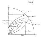
- the method according to the invention is based on two Described embodiments whose Q-H diagrams in the Fig. 1 and 2 are shown.
- the flow rate Q is on the abscissa in the Q-H diagrams and the head H is plotted on the ordinate axis.
- the Maximum curve is marked 1 in the figures, it gives the maximum hydraulic power of the pump set at and limits the hydraulic power field upwards. How one from this maximum curve 1, the largest possible Head reached on this maximum curve when the Flow rate is 0. Conversely, the largest possible Flow rate can be reached when the delivery head is 0.
- the electric motor driven and speed controllable Heating circulation pump unit can be placed under this in any point Maximum curve 1 can be operated.
- the first method step now consists in determining a maximum delivery flow Q max in accordance with the preliminary calculations and setting it on the pump unit, so that a Q max line which limits the power field of the pump in the QH field results in parallel with the ordinate axis. Where this Q max line intersects the maximum curve 1, if no other delivery head is specified, a first maximum delivery head H 1 max . At this point of intersection of the Q max line with the maximum curve 1 is also the point of the maximum pump output. It does not make sense to let the delivery head rise above this point, since the delivery rate will then be lower than the maximum delivery rate Q max .
- the third process step in which the maximum delivery head of the pump is adapted to the heating system, takes place when the pump is operating.
- the maximum flow rate Q max previously determined in the first method step must be reached during operation. If the actual delivery head H of the pump then reaches a value that is 20% below the previously defined maximum delivery head H 1 max , the maximum delivery head is automatically reduced to H 2 max .
- H 2 max corresponds to 90% of H 1 max . If the actual delivery head H of the pump falls below the actual delivery head H of the pump by 20% even with this reduced maximum delivery head H 2 max at maximum delivery flow Q max , the maximum delivery head is automatically limited to a value H 3 max , which in turn is 90% of H 2 max corresponds.
- the performance field is further limited by a minimum curve 8, which intersects the ordinate axis at H min and intersects the maximum curve 1 at a value at which the actual flow rate Q corresponds to 40% of the maximum flow rate Q max .
- a flow rate Q ' max is drawn in in FIG. 1, which is provided for night operation when the flow temperature is lowered and the heating system is not expected to operate under full load.
- the performance field of the pump is further limited in this way to smaller outputs during night operation.
- the maximum flow rate of the pump is limited to Q ' max .
- the night temperature drop is recorded by determining the temperature gradient of the fluid being conveyed, suitable limit values being defined which prevent a changeover in the event of temperature fluctuations which usually occur during day operation.
- the previously determined maximum flow rate Q max is reduced to a reduced maximum flow rate Q ' max and, conversely, is reset when a predetermined positive value of the temperature gradient is reached.
- the process steps two and three and the establishment of a minimum curve 8 can be carried out automatically by a corresponding electronic control of the pump, so it is only necessary to set and determine the maximum delivery flow Q max before the pump is operated, after which the control system automatically adjusts the maximum delivery head H 1 max as well as subsequently determined and determined in operation H nmax .
- the adaptation process can be accelerated if, in addition to Q max , the approximately previously calculated maximum delivery head H 1 'max is entered, which must be below H 1 max .
- the method variant shown with reference to FIG. 2 differs from the method described with reference to FIG. 1 in that instead of the constant delivery heights H n max, proportional pressure curves H n max (Q) are defined, which means that the pump's power field is adapted more smoothly the system requirements are met, in the part-load range.
- H n max proportional pressure curves H n max (Q) are defined, which means that the pump's power field is adapted more smoothly the system requirements are met, in the part-load range.
- the line H 1 max from Fig. 1 is shown as an example, which is intended to clarify that the second and third process step in principle take place in the same way as described above, but that the gradation applies only to the maximum flow rate Q max , otherwise however, has the curve shown in FIG. 2.
- method steps 2 and 3 for lowering the maximum delivery head take place automatically by regulating the unit.
Landscapes
- Engineering & Computer Science (AREA)
- Mechanical Engineering (AREA)
- General Engineering & Computer Science (AREA)
- Physics & Mathematics (AREA)
- Thermal Sciences (AREA)
- Chemical & Material Sciences (AREA)
- Combustion & Propulsion (AREA)
- Control Of Positive-Displacement Pumps (AREA)
Description
Claims (8)
- Verfahren zur Leistungsbegrenzung von elektromotorisch angetriebenen drehzahlsteuerbaren Heizungsumwälzpumpen, deren hydraulisches Leistungsfeld durch eine Maximalkurve (1) im Q-H-Feld begrenzt ist, wobei Q den Förderstrom und H die Förderhöhe darstellen,dadurch gekennzeichnet,bei dem zunächst ein maximaler Förderstrom (Qmax) der Pumpe festgelegt wird,bei dem dann eine unter dem Schnittpunkt der Maximalkurve (1) mit dem festgelegten maximalen Förderstrom (Qmax) liegende oder diesem entsprechende maximale Förderhöhe (H1 max) der Pumpe festgelegt wird,daß beim Betrieb der Pumpe, wenn die tätsächliche Förderhöhe (H) die zuvor festgelegte maximale Förderhöhe (H1 max bzw. Hn max) bei Erreichen des festgelegten maximalen Förderstromes (Qmax) um ein vorgegebenes Maß unterschreitet, selbsttätig eine entsprechend niedrigere maximale Förderhöhe (Hn+1 max) festgelegt wird.
- Verfahren nach Anspruch 1, dadurch gekennzeichnet, daß anstelle einer konstanten maximalen Förderhöhe (Hn max) eine maximale Förderhöhe (Hn max=f(Q))in Form einer Funktion in Abhängigkeit des Förderstromes (Q) festgelegt wird.
- Verfahren nach einem der vorhergehenden Ansprüche, dadurch gekennzeichnet, daß das unter der Q-H-Kurve liegende Leistungsfeld durch eine Minimalkurve (8) begrenzt wird, die von einer minimalen Förderhöhe (Hmin) bei einem Förderstrom (Q) von Q = 0 ausgeht und die Maximalkurve (1) bei 0,25 ≤ Q/Qopt ≤ 0,5 schneidet.
- Verfahren nach einem der vorhergehenden Ansprüche, dadurch gekennzeichnet, daß die maximale Förderhöhe (Hn max) nur dann auf eine niedrigere maximale Förderhöhe (Hn+1 max) festgelegt wird, wenn die tatsächliche Förderhöhe (H) der Pumpe die zuvor festgelegte maximale Förderhöhe (Hn max) bei maximalem Förderstrom (Qmax) um mindestens zehn Prozent unterschreitet, wobei die niedrigere maximale Förderhöhe (Hn+1 max) auf einen Wert zwischen der tatsächlichen Förderhöhe (H) und der zuvor festgelegten maximalen Förderhöhe (Hn max) festgelegt wird, bevorzugt auf den Mittelwert.
- Verfahren nach einem der vorhergehenden Ansprüche, dadurch gekennzeichnet, daß der Temperaturgradient des geförderten Fluids ermittelt wird, daß beim Betrieb der Pumpe mit maximalem Förderstrom (Qmax) und bei Erreichen eines vorgegebenen negativen Wertes des Temperaturgradienten der zuvor festgelegte maximale Förderstrom (Qmax) um ein vorgegebenes Maß (auf Q'max) vermindert wird und daß bei Erreichen eines vorgebenen positiven Wertes des Temperaturgradienten der maximale Förderstrom ( von Q'max) auf den ursprünglichen höheren Wert (Qmax) zurückgesetzt wird.
- Verfahren nach einem der vorhergehenden Ansprüche, dadurch gekennzeichnet, daß während der Zeit, in der der maximale Förderstrom aufgrund des negativen Temperaturgradienten des geförderten Fluids abgesenkt ist, keine Absenkung der maximalen Förderhöhe erfolgt.
- Vorrichtung zur Ausführung des Verfahrens nach einem der vorhergehenden Ansprüche, bei der eine Eingabeeinrichtung vorgesehen ist, über die ein maximaler Förderstrom (Qmax) der Pumpe festlegbar ist,
und bei der Mittel vorgesehen sind, die anhand des Schnittpunktes der Maximalkurve mit dem festgelegten maximalen Förderstrom (Qmax) selbsttätig eine maximale Förderhöhe (H1 max) der Pumpe festlegen, dadurch gekennzeichnet, daß weitere Mittel vorgesehen sind, die beim Betrieb der Pumpe dann, wenn die tatsächliche Förderhöhe der Pumpe die zuvor festgelegte maximale Förderhöhe (H1 max bzw. Hn max) bei Erreichen des festgelegten maximalen Förderstromes (Qmax) um ein vorgegebenes Maß unterschreitet, selbsttätig eine entsprechend niedrigere maximale Förderhöhe (Hn+1 max) festlegen. - Vorrichtung nach Anspruch 7, dadurch gekennzeichnet, daß eine weitere Eingabevorrichtung vorgesehen ist, über die eine maximale Förderhöhe (H1' max) festlegbar ist.
Applications Claiming Priority (2)
| Application Number | Priority Date | Filing Date | Title |
|---|---|---|---|
| DE19504232 | 1995-02-09 | ||
| DE19504232A DE19504232A1 (de) | 1995-02-09 | 1995-02-09 | Verfahren zur Leistungsbegrenzung von elektrisch angetriebenen Heizungsumwälzpumpen |
Publications (2)
| Publication Number | Publication Date |
|---|---|
| EP0726396A1 EP0726396A1 (de) | 1996-08-14 |
| EP0726396B1 true EP0726396B1 (de) | 1998-09-23 |
Family
ID=7753524
Family Applications (1)
| Application Number | Title | Priority Date | Filing Date |
|---|---|---|---|
| EP96101323A Expired - Lifetime EP0726396B1 (de) | 1995-02-09 | 1996-01-31 | Verfahren zur Leistungsbegrenzung von elektrisch angetriebenen Heizungsumwälzpumpen |
Country Status (2)
| Country | Link |
|---|---|
| EP (1) | EP0726396B1 (de) |
| DE (2) | DE19504232A1 (de) |
Cited By (4)
| Publication number | Priority date | Publication date | Assignee | Title |
|---|---|---|---|---|
| DE102014016791A1 (de) | 2014-11-14 | 2016-05-19 | Paw Gmbh & Co. Kg | Verfahren zur hydraulischen Regelung mehrerer Heizkreisläufe am Verteilerbalken |
| DE102015006779A1 (de) | 2015-06-01 | 2016-12-01 | Paw Gmbh & Co. Kg | Verfahren zum Betreiben einer Heizungsanlage und Regler mit Differenzdrucksensor |
| EP3443228B1 (de) | 2016-04-15 | 2024-01-03 | Wilo Se | Kreiselpumpenaggregat und verfahren zu seiner betriebseinstellung |
| WO2025002619A1 (en) | 2023-06-30 | 2025-01-02 | Grundfos Holding A/S | Method for controlling a circulation pump |
Families Citing this family (11)
| Publication number | Priority date | Publication date | Assignee | Title |
|---|---|---|---|---|
| DE19513394B4 (de) * | 1995-04-08 | 2006-06-14 | Wilo Ag | Temperaturgeführte Leistungsansteuerung für elektrisch betriebene Pumpenaggregate |
| DE10163989A1 (de) * | 2001-12-24 | 2003-07-10 | Grundfos As | Verfahren zum Steuern einer drehzahlregelbaren Heizungsumwälzpumpe |
| DE10163987A1 (de) * | 2001-12-24 | 2003-07-10 | Grundfos As | Verfahren zum Steuern einer drehzahlregelbaren Heizungsumwälzpumpe |
| DE102011008165A1 (de) * | 2011-01-10 | 2012-07-12 | Wilo Se | Verfahen zum leistungsoptimierten Betreiben einer elektromotorisch angetriebenen Pumpe bei geringen Volumenströmen |
| DE102011012211A1 (de) * | 2011-02-23 | 2012-08-23 | Wilo Se | Leistungsoptimiertes Betreiben einer elektromotorisch angetriebenen Pumpe durch Mitkopplung |
| WO2013090907A1 (en) * | 2011-12-16 | 2013-06-20 | Fluid Handling Llc | Dynamic linear control methods and apparatus for variable speed pump control |
| DE102013204607A1 (de) * | 2013-03-15 | 2014-09-18 | Thomas Stahl | Regelung eines Volumenstroms bei Pumpen bei geringen Volumenströmen |
| DE102014018020A1 (de) * | 2014-12-08 | 2016-06-09 | Wilo Se | Verfahren zum Betreiben einer Kreiselpumpe |
| DE102019004317A1 (de) * | 2019-06-19 | 2020-12-24 | KSB SE & Co. KGaA | Verfahren zur Regelung einer Umwälzpumpe sowie Umwälzpumpe |
| CN112240287B (zh) * | 2020-10-19 | 2022-07-19 | 西安热工研究院有限公司 | 一种火电机组循环水泵在线诊断系统及方法 |
| CN113656969B (zh) * | 2021-08-18 | 2023-09-08 | 中铁二院华东勘察设计有限责任公司 | 一种适用于轨道交通地下区间道床泵站的水泵选型方法 |
Family Cites Families (9)
| Publication number | Priority date | Publication date | Assignee | Title |
|---|---|---|---|---|
| CH573054A5 (en) * | 1974-07-31 | 1976-02-27 | Iberag Ag | Pump with steplessly adjustable head and delivery - has constant speed main pump and variable speed additional pump |
| DE3149401C2 (de) * | 1981-12-10 | 1984-10-11 | Fa. Rud. Otto Meyer, 2000 Hamburg | Heizungsanlage |
| FR2524943B1 (fr) * | 1982-04-09 | 1986-11-07 | Salmson Pompes | Ensemble de pompage, tel qu'un circulateur pour installation de chauffage central, a caracteristique hydraulique predeterminee |
| DE3225141C2 (de) * | 1982-07-06 | 1984-12-20 | Grundfos A/S, Bjerringbro | Drehzahlgeregeltes Pumpenaggregat |
| US4518318A (en) * | 1983-07-07 | 1985-05-21 | Grundfos A/S | Pumping sets |
| DE3402120A1 (de) * | 1984-01-23 | 1985-07-25 | Rheinhütte vorm. Ludwig Beck GmbH & Co, 6200 Wiesbaden | Verfahren und vorrichtung zur regelung verschiedener betriebsparameter bei pumpen und verdichtern |
| DE3542370C2 (de) * | 1985-11-30 | 2003-06-05 | Wilo Gmbh | Verfahren zum Regeln der Förderhöhe einer Pumpe |
| ES2004337T5 (es) * | 1987-01-29 | 1997-03-16 | Ewald Hennel | Procedimiento para regular el caudal impelido por una bomba de circulacion. |
| DE3824057A1 (de) * | 1988-07-15 | 1990-01-25 | Loewe Pumpenfabrik Gmbh | Verfahren zur regelung des betriebes von pumpen |
-
1995
- 1995-02-09 DE DE19504232A patent/DE19504232A1/de not_active Ceased
-
1996
- 1996-01-31 EP EP96101323A patent/EP0726396B1/de not_active Expired - Lifetime
- 1996-01-31 DE DE59600586T patent/DE59600586D1/de not_active Expired - Lifetime
Cited By (7)
| Publication number | Priority date | Publication date | Assignee | Title |
|---|---|---|---|---|
| DE102014016791A1 (de) | 2014-11-14 | 2016-05-19 | Paw Gmbh & Co. Kg | Verfahren zur hydraulischen Regelung mehrerer Heizkreisläufe am Verteilerbalken |
| EP3026352A1 (de) | 2014-11-14 | 2016-06-01 | PAW GmbH & Co. KG | Verfahren zur hydraulischen regelung mehrerer heizkreisläufe am verteilerbalken |
| DE102014016791B4 (de) | 2014-11-14 | 2022-05-12 | Paw Gmbh & Co. Kg | Verfahren zur hydraulischen Regelung mehrerer Heizkreisläufe am Verteilerbalken |
| DE102015006779A1 (de) | 2015-06-01 | 2016-12-01 | Paw Gmbh & Co. Kg | Verfahren zum Betreiben einer Heizungsanlage und Regler mit Differenzdrucksensor |
| EP3101352A1 (de) | 2015-06-01 | 2016-12-07 | PAW GmbH & Co. KG | Verfahren zum betreiben einer heizungsanlage und regler mit differenzdrucksensor |
| EP3443228B1 (de) | 2016-04-15 | 2024-01-03 | Wilo Se | Kreiselpumpenaggregat und verfahren zu seiner betriebseinstellung |
| WO2025002619A1 (en) | 2023-06-30 | 2025-01-02 | Grundfos Holding A/S | Method for controlling a circulation pump |
Also Published As
| Publication number | Publication date |
|---|---|
| DE19504232A1 (de) | 1996-08-22 |
| EP0726396A1 (de) | 1996-08-14 |
| DE59600586D1 (de) | 1998-10-29 |
Similar Documents
| Publication | Publication Date | Title |
|---|---|---|
| EP0726396B1 (de) | Verfahren zur Leistungsbegrenzung von elektrisch angetriebenen Heizungsumwälzpumpen | |
| EP2663774B1 (de) | Verfahren zum leistungsoptimierten betreiben einer elektromotorisch angetriebenen pumpe bei geringen volumenströmen | |
| EP1323986B1 (de) | Verfahren zum Steuern einer drehregelbaren Heizungsumwälzpumpe | |
| EP2863134B1 (de) | Verfahren zum Anpassen einer Heizkurve | |
| DE10356971B4 (de) | Schaltung zum Regeln der Speisungsmenge einer hydraulischen Pumpe | |
| EP2678563B1 (de) | Leistungsoptimiertes betreiben einer elektromotorisch angetriebenen pumpe durch mitkopplung | |
| DE102009039515A1 (de) | Vakuumtherapievorrichtung | |
| DE69009272T2 (de) | Motorpumpengruppe mit Druck- und Förderstromsensoren. | |
| DE19781253B4 (de) | Druckzerstäuberbrenner für ein motorunabhängiges Fahrzeugheizgerät | |
| EP2940309B1 (de) | Verfahren zur Regelung eines Pumpensystems und geregeltes Pumpensystem | |
| DE10010670C2 (de) | Hydraulische Hubvorrichtung für batteriebetriebene Flurförderzeuge | |
| EP3722680B1 (de) | Verfahren zur durchführung eines hydraulischen abgleichs eines heizsystems für ein gebäude sowie dazu ausgebildetes heizsystem | |
| WO2008067919A1 (de) | Verfahren zum steuern einer drehzahlregelbaren heizungsumwälzpumpe | |
| EP0223208B1 (de) | Verfahren und Einrichtung zum Regeln von Turbokompressoren | |
| DE3203832A1 (de) | Verfahren und regelvorrichtung zum regeln eines heizungskreises | |
| CH643914A5 (de) | Mehrstufige, hydraulische maschine und verfahren zu ihrem betrieb. | |
| EP4189295B1 (de) | Verfahren zur regelung einer umwälzpumpe, insbesondere heizungspumpe | |
| EP4684134A1 (de) | Verfahren zur regelung eines pumpensystems, das zumindest zwei hydraulisch parallel betriebene kreiselpumpen aufweist, sowie mehrpumpensystem | |
| DE102018200652A1 (de) | Verfahren zur Regelung einer Umwälzpumpe sowie Umwälzpumpe | |
| DE19824543C5 (de) | Verfahren zur Regelung von Umwälzpumpen in den Solarkollektorkreisen von Solaranlagen mit Speicher | |
| DE3409340A1 (de) | Verfahren zum steuern des betriebes einer mehrstufigen hydraulischen maschine | |
| DE10114822A1 (de) | Verfahren und Vorrichtung zum Regeln oder Steuern der Energiezufuhr zu Heizkörpern in einem Heizsystem und Verwendung einer Pumpe zu diesem Zweck | |
| DE102022203051B3 (de) | Verfahren zum Betreiben einer drehzahlvariablen Pumpe | |
| DE4201100A1 (de) | Einrichtung zur regelung des foerderstroms einer kreiselpumpe in geschlossenem rohrnetz | |
| DE852393C (de) | Vorrichtung fuer Dampfturbinen-Ein- und -Mehrfach-Entnahme- und -Zwei- und -Mehrdruckregelungen, die durch Druckfluessigkeit betrieben werden |
Legal Events
| Date | Code | Title | Description |
|---|---|---|---|
| PUAI | Public reference made under article 153(3) epc to a published international application that has entered the european phase |
Free format text: ORIGINAL CODE: 0009012 |
|
| AK | Designated contracting states |
Kind code of ref document: A1 Designated state(s): DE FR GB IT |
|
| 17P | Request for examination filed |
Effective date: 19960911 |
|
| 17Q | First examination report despatched |
Effective date: 19970717 |
|
| GRAG | Despatch of communication of intention to grant |
Free format text: ORIGINAL CODE: EPIDOS AGRA |
|
| GRAG | Despatch of communication of intention to grant |
Free format text: ORIGINAL CODE: EPIDOS AGRA |
|
| GRAH | Despatch of communication of intention to grant a patent |
Free format text: ORIGINAL CODE: EPIDOS IGRA |
|
| GRAH | Despatch of communication of intention to grant a patent |
Free format text: ORIGINAL CODE: EPIDOS IGRA |
|
| GRAA | (expected) grant |
Free format text: ORIGINAL CODE: 0009210 |
|
| AK | Designated contracting states |
Kind code of ref document: B1 Designated state(s): DE FR GB IT |
|
| REF | Corresponds to: |
Ref document number: 59600586 Country of ref document: DE Date of ref document: 19981029 |
|
| GBT | Gb: translation of ep patent filed (gb section 77(6)(a)/1977) |
Effective date: 19981013 |
|
| ET | Fr: translation filed | ||
| PLBQ | Unpublished change to opponent data |
Free format text: ORIGINAL CODE: EPIDOS OPPO |
|
| PLBI | Opposition filed |
Free format text: ORIGINAL CODE: 0009260 |
|
| PLBF | Reply of patent proprietor to notice(s) of opposition |
Free format text: ORIGINAL CODE: EPIDOS OBSO |
|
| 26 | Opposition filed |
Opponent name: WILO GMBH Effective date: 19990623 |
|
| PLBF | Reply of patent proprietor to notice(s) of opposition |
Free format text: ORIGINAL CODE: EPIDOS OBSO |
|
| PLBF | Reply of patent proprietor to notice(s) of opposition |
Free format text: ORIGINAL CODE: EPIDOS OBSO |
|
| PLBO | Opposition rejected |
Free format text: ORIGINAL CODE: EPIDOS REJO |
|
| PLBN | Opposition rejected |
Free format text: ORIGINAL CODE: 0009273 |
|
| STAA | Information on the status of an ep patent application or granted ep patent |
Free format text: STATUS: OPPOSITION REJECTED |
|
| 27O | Opposition rejected |
Effective date: 20010125 |
|
| REG | Reference to a national code |
Ref country code: GB Ref legal event code: IF02 |
|
| PG25 | Lapsed in a contracting state [announced via postgrant information from national office to epo] |
Ref country code: IT Free format text: LAPSE BECAUSE OF NON-PAYMENT OF DUE FEES;WARNING: LAPSES OF ITALIAN PATENTS WITH EFFECTIVE DATE BEFORE 2007 MAY HAVE OCCURRED AT ANY TIME BEFORE 2007. THE CORRECT EFFECTIVE DATE MAY BE DIFFERENT FROM THE ONE RECORDED. Effective date: 20050131 |
|
| PLAB | Opposition data, opponent's data or that of the opponent's representative modified |
Free format text: ORIGINAL CODE: 0009299OPPO |
|
| PGRI | Patent reinstated in contracting state [announced from national office to epo] |
Ref country code: IT Effective date: 20091201 |
|
| PGFP | Annual fee paid to national office [announced via postgrant information from national office to epo] |
Ref country code: GB Payment date: 20141218 Year of fee payment: 20 |
|
| PGFP | Annual fee paid to national office [announced via postgrant information from national office to epo] |
Ref country code: FR Payment date: 20141121 Year of fee payment: 20 |
|
| PGFP | Annual fee paid to national office [announced via postgrant information from national office to epo] |
Ref country code: IT Payment date: 20141210 Year of fee payment: 20 |
|
| PGFP | Annual fee paid to national office [announced via postgrant information from national office to epo] |
Ref country code: DE Payment date: 20150127 Year of fee payment: 20 |
|
| REG | Reference to a national code |
Ref country code: DE Ref legal event code: R071 Ref document number: 59600586 Country of ref document: DE |
|
| REG | Reference to a national code |
Ref country code: GB Ref legal event code: PE20 Expiry date: 20160130 |
|
| PG25 | Lapsed in a contracting state [announced via postgrant information from national office to epo] |
Ref country code: GB Free format text: LAPSE BECAUSE OF EXPIRATION OF PROTECTION Effective date: 20160130 |