EP0725458A2 - Profilschiene eines Möbels oder eines sonstigen Gewerkes - Google Patents
Profilschiene eines Möbels oder eines sonstigen Gewerkes Download PDFInfo
- Publication number
- EP0725458A2 EP0725458A2 EP95113093A EP95113093A EP0725458A2 EP 0725458 A2 EP0725458 A2 EP 0725458A2 EP 95113093 A EP95113093 A EP 95113093A EP 95113093 A EP95113093 A EP 95113093A EP 0725458 A2 EP0725458 A2 EP 0725458A2
- Authority
- EP
- European Patent Office
- Prior art keywords
- profile rail
- groove
- rail according
- adapter
- cables
- Prior art date
- Legal status (The legal status is an assumption and is not a legal conclusion. Google has not performed a legal analysis and makes no representation as to the accuracy of the status listed.)
- Granted
Links
- 239000002184 metal Substances 0.000 claims description 2
- 239000011810 insulating material Substances 0.000 abstract description 2
- 238000009434 installation Methods 0.000 abstract 1
- 239000012774 insulation material Substances 0.000 description 2
- 230000004308 accommodation Effects 0.000 description 1
- 239000012772 electrical insulation material Substances 0.000 description 1
Images

Classifications
-
- A—HUMAN NECESSITIES
- A47—FURNITURE; DOMESTIC ARTICLES OR APPLIANCES; COFFEE MILLS; SPICE MILLS; SUCTION CLEANERS IN GENERAL
- A47B—TABLES; DESKS; OFFICE FURNITURE; CABINETS; DRAWERS; GENERAL DETAILS OF FURNITURE
- A47B96/00—Details of cabinets, racks or shelf units not covered by a single one of groups A47B43/00 - A47B95/00; General details of furniture
- A47B96/14—Bars, uprights, struts, or like supports, for cabinets, brackets, or the like
-
- H—ELECTRICITY
- H01—ELECTRIC ELEMENTS
- H01R—ELECTRICALLY-CONDUCTIVE CONNECTIONS; STRUCTURAL ASSOCIATIONS OF A PLURALITY OF MUTUALLY-INSULATED ELECTRICAL CONNECTING ELEMENTS; COUPLING DEVICES; CURRENT COLLECTORS
- H01R25/00—Coupling parts adapted for simultaneous co-operation with two or more identical counterparts, e.g. for distributing energy to two or more circuits
- H01R25/14—Rails or bus-bars constructed so that the counterparts can be connected thereto at any point along their length
-
- H—ELECTRICITY
- H02—GENERATION; CONVERSION OR DISTRIBUTION OF ELECTRIC POWER
- H02B—BOARDS, SUBSTATIONS OR SWITCHING ARRANGEMENTS FOR THE SUPPLY OR DISTRIBUTION OF ELECTRIC POWER
- H02B1/00—Frameworks, boards, panels, desks, casings; Details of substations or switching arrangements
- H02B1/26—Casings; Parts thereof or accessories therefor
- H02B1/30—Cabinet-type casings; Parts thereof or accessories therefor
- H02B1/306—Accessories, e.g. windows
-
- F—MECHANICAL ENGINEERING; LIGHTING; HEATING; WEAPONS; BLASTING
- F21—LIGHTING
- F21V—FUNCTIONAL FEATURES OR DETAILS OF LIGHTING DEVICES OR SYSTEMS THEREOF; STRUCTURAL COMBINATIONS OF LIGHTING DEVICES WITH OTHER ARTICLES, NOT OTHERWISE PROVIDED FOR
- F21V21/00—Supporting, suspending, or attaching arrangements for lighting devices; Hand grips
- F21V21/34—Supporting elements displaceable along a guiding element
- F21V21/35—Supporting elements displaceable along a guiding element with direct electrical contact between the supporting element and electric conductors running along the guiding element
-
- H—ELECTRICITY
- H01—ELECTRIC ELEMENTS
- H01R—ELECTRICALLY-CONDUCTIVE CONNECTIONS; STRUCTURAL ASSOCIATIONS OF A PLURALITY OF MUTUALLY-INSULATED ELECTRICAL CONNECTING ELEMENTS; COUPLING DEVICES; CURRENT COLLECTORS
- H01R4/00—Electrically-conductive connections between two or more conductive members in direct contact, i.e. touching one another; Means for effecting or maintaining such contact; Electrically-conductive connections having two or more spaced connecting locations for conductors and using contact members penetrating insulation
- H01R4/24—Connections using contact members penetrating or cutting insulation or cable strands
- H01R4/2404—Connections using contact members penetrating or cutting insulation or cable strands the contact members having teeth, prongs, pins or needles penetrating the insulation
- H01R4/2406—Connections using contact members penetrating or cutting insulation or cable strands the contact members having teeth, prongs, pins or needles penetrating the insulation having needles or pins
Definitions
- the invention relates to a profile rail as a load-bearing component of a frame for exhibition or trade fair stands, a shelf, other furniture or another work.
- the invention has for its object to design a profile rail of the type mentioned so that it allows a concealed accommodation of electrical, low-voltage cables.
- the profile rail has a groove open to the outside, the bottom of which is provided with two parallel grooves for storing and fixing two electrical cables, the groove in the lateral groove walls undercut surfaces for positive and / or non-positive Has an adapter.
- the channels for receiving the cables are formed as circular shapes which merge into one another in the center of the bottom of the groove and extend slightly into the wall area.
- the cables which are preferably designed as stranded cables, are covered with a jacket enclosed, which consists of electrical insulation material.
- the walls of the groove have recesses adjacent to the groove opening, into which fastening elements of an adapter are spring-loaded.
- the adapter is equipped with current contact pins which, when the adapter is inserted into the groove, extend into the associated cable and lead to lighting which is fastened to the adapter or to parts which are fixed to the adapter.
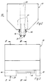
- the profile rail 1 shown in FIG. 1 is triangular in cross section and has a rectangular, outwardly open groove 2, the bottom of which is formed by two parallel grooves 3, which are used for storing and fixing an electrical cable 4.
- These cables are preferably designed as stranded cables and have a jacket 5 made of electrical insulating material.
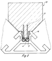
- the grooves 3 are designed as circular shapes which are in the center of the bottom of the groove 2 merge into each other and extend slightly into the area of the walls 6 and 7. Due to this spatial shape of the channels, the inserted cables, which are supported in the central region, as can be seen in FIGS. 4 and 5, and which extend with their jackets 5 made of insulation material into the wall recesses 8, are shaped and formed in these channels non-positively fixed.
- the groove walls 6, 7 are provided with recesses 10, 11 adjacent to the groove opening 9, so that projections 12 result which form the groove boundary edges of the groove opening 9.
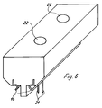
- an adapter 13 is placed on the profile rail 1, which is equipped with rectangular webs 14, 15 which extend into the groove 2 and end at a short distance above the cables 4.
- the adapter 13 is made of an insulating plastic.
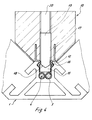
- Fig. 4 it follows that the adapter 13 is fixed to the profile rail 1 by resilient clamping legs 16 made of sheet metal, the fastening part 17 is embedded in the adapter body.
- the clamping leg 16 protruding from the adapter body is angular in the exemplary embodiment according to FIG. 4 and engages in the recess 10 or 11, the clamping leg engaging behind the projection 12.
- the recesses 10, 11 have the shape of an isosceles triangle with a leg angle of 90 °.
- clamping legs can, as shown in FIG. 4, be limited by the end pin 18 of a fixing screw 19 which is inserted into a threaded bore 20 of the adapter is screwed, which is arranged between the clamping legs.
- the end pin 18 can also be designed so that it presses in the position shown in FIG. 4 onto the clamping legs and brings them into a press connection with the profile rail 1, so that the adapter 13 is non-positively against movement in the longitudinal or longitudinal direction of the groove Profile rail 1 is set.
- An electrical connection (not shown) is present between the current contact pins 21 and a current tap 22 provided on the adapter for electrical lighting.
- the groove 2 is rectangular in cross section.
- the cross-sectional shape of the profile rail 1 can be constructed differently.
- the profile rail is equipped with a trapezoidal hollow chamber 23 and has receiving grooves 24 for components, these grooves being opened to the side surfaces of the profile rail.
- the assembly of the cables and the adapter which can be provided at any point in the area of the groove 2, can be carried out without tools.
- the disassembly of these parts can also be carried out in a simple manner.
Landscapes
- Engineering & Computer Science (AREA)
- Power Engineering (AREA)
- Installation Of Indoor Wiring (AREA)
- Machines For Laying And Maintaining Railways (AREA)
- Drawers Of Furniture (AREA)
- Cleaning Implements For Floors, Carpets, Furniture, Walls, And The Like (AREA)
- Buildings Adapted To Withstand Abnormal External Influences (AREA)
- Measurement Of The Respiration, Hearing Ability, Form, And Blood Characteristics Of Living Organisms (AREA)
Abstract
Description
- Die Erfindung betrifft eine Profilschiene als tragendes Bauteil eines Gestelles für Ausstellungs- oder Messestände, eines Regals, eines sonstigen Möbels oder eines anderen Gewerkes.
- Der Erfindung liegt die Aufgabe zugrunde, eine Profilschiene der genannten Art so zu gestalten, daß sie eine verdeckte Aufnahme von elektrischen, an Niederspannung liegenden Kabeln ermöglicht.
- Diese Aufgabe wird erfindungsgemäß dadurch gelöst, daß die Profilschiene eine zur Außenseite geöffnete Nut aufweist, deren Boden mit zwei parallel zueinander verlaufenden Rinnen zur Einlagerung und Festlegung zweier elektrischer Kabel versehen ist, wobei die Nut in den seitlichen Nutwänden hinterschnittene Flächen zur formschlüssigen oder/und kraftschlüssigen Festlegung eines Adapters aufweist.
- Bei einer vorteilhaften Ausführungsform sind die Rinnen zur Kabelaufnahme als Kreisausformungen ausgebildet, die in der Bodenmitte der Nut ineinander übergehen und sich geringfügig in den Wandungsbereich erstrecken. Hierdurch werden die in die Rinnen eingelegten Kabel formschlüssig in der Nut fixiert.
- Um zu vermeiden, daß die Profilschiene an Spannung liegt, werden die Kabel, die vorzugsweise als Litzenkabel ausgeführt werden, mit einem Mantel umschlossen, der aus elektrischem Isolationsmaterial besteht.
- Die Wände der Nut weisen benachbart der Nutöffnung Ausnehmungen auf, in die Befestigungselemente eines Adapters eingefedert werden.
- Der Adapter ist mit Stromkontaktstiften ausgerüstet, die sich bei in die Nut eingesetztem Adapter bis in das zugeordnete Kabel erstrecken und zu einer Beleuchtung führen, die an dem Adapter oder an adapterfesten Teilen befestigt ist.
- Weitere Ausgestaltungen der Erfindung ergeben sich aus den Unteransprüchen und der folgenden Beschreibung eines Ausführungsbeispiels einer Profilschiene.
- Es zeigen:
- Fig. 1
- eine Profilschiene im Querschnitt,
- Fig. 2
- die Stirnansicht eines in die nach oben offene Nut der Profilschiene nach Fig. 1 einsetzbaren Adapters,
- Fig. 3
- eine Ansicht in Richtung des Pfeiles III in Fig. 2,
- Fig. 4
- den in die Nut der Profilschiene nach Fig. 1 eingesetzten Adapter im Schnitt nach der Linie IV-IV in Fig. 3,
- Fig. 5
- den in die Nut der Profilschiene nach Fig. 1 eingesetzten Adapter im Schnitt nach der Linie V-V in Fig. 3 und
- Fig. 6
- einen Adapter in perspektivischer Darstellung.
- Die in der Fig. 1 aufgezeigte Profilschiene 1 ist im Querschnitt dreieckförmig ausgebildet und weist eine rechteckförmige, nach außen geöffnete Nut 2 auf, deren Boden durch zwei parallel zueinander verlaufende Rinnen 3 gebildet wird, die zur Einlagerung und Festlegung eines elektrischen Kabels 4 dienen. Diese Kabel sind vorzugsweise als Litzenkabel ausgebildet und weisen einen Mantel 5 aus elektrischem Isoliermaterial auf.
- In dem Ausführungsbeispiel nach der Fig. 1 und den Fig. 4 und 5 sind die Rinnen 3 als Kreisausformungen ausgebildet, die in der Bodenmitte der Nut 2 ineinander übergehen und sich geringfügig in den Bereich der Wandungen 6 und 7 erstrecken. Durch diese Raumform der Rinnen werden die eingelegten Kabel, die sich im mittleren Bereich, wie sich aus den Fig. 4 und 5 ergibt, aneinander abstützen und die mit ihren Mänteln 5 aus Isolationsmaterial in die Wandungsausnehmungen 8 sich erstrecken, in diesen Rinnen form- und kraftschlüssig festgelegt.
- Die Nutwandungen 6,7 sind benachbart der Nutöffnung 9 mit Ausnehmungen 10,11 versehen, so daß sich Vorsprünge 12 ergeben, die die Nutbegrenzungskanten der Nutöffnung 9 bilden.
- Nach dem Einlegen der Kabel 4 in die Rinnen 3 wird ein Adapter 13 auf die Profilschiene 1 gesetzt, der mit rechteckförmigen Stegen 14,15 ausgerüstet ist, die sich in die Nut 2 erstrecken und in einem geringen Abstand oberhalb der Kabel 4 enden. Der Adapter 13 wird aus einem isolierenden Kunststoff gefertigt.
- Aus der Fig. 4 ergibt sich, daß der Adapter 13 an der Profilschiene 1 durch federnde, aus Blech gefertigte Klemmschenkel 16 festgelegt wird, deren Befestigungsteil 17 im Adapterkörper eingebettet ist. Der aus dem Adapterkörper herausragende Klemmschenkel 16 ist in dem Ausführungsbeispiel nach der Fig. 4 winkelförmig ausgebildet und greift in die Ausnehmung 10 bzw. 11 ein, wobei der Klemmschenkel den Vorsprung 12 hintergreift.
- Die Ausnehmungen 10,11 haben in dem Ausführungsbeispiel nach der Fig. 1 die Form eines gleichschenkligen Dreiecks mit einem Schenkelwinkel von 90°.
- Aus der Fig. 3 ergibt sich, daß die Klemmschenkel 16 zwischen den Stegen 14 und 15 angeordnet sind.
- Der Federweg dieser Klemmschenkel kann, wie die Fig. 4 zeigt, durch den Endzapfen 18 einer Fixierschraube 19 begrenzt werden, die in eine Gewindebohrung 20 des Adapters eingeschraubt wird, die zwischen den Klemmschenkeln angeordnet ist.
- Der Endzapfen 18 kann auch so ausgebildet sein, daß er in der Fig. 4 aufgezeigten Stellung auf die Klemmschenkel drückt und diese in eine Preßverbindung mit der Profilschiene 1 bringt, so daß der Adapter 13 kraftschlüssig gegenüber einer Bewegung in Nutlängsrichtung bzw. in der Längsrichtung der Profilschiene 1 festgelegt ist.
- Aus den Fig. 3 und 5 ergibt sich, daß in den Steg 14 des Adapters 13 Stromkontaktstifte 21 angeordnet sind, die aus dem Steg 14 herausragen und bei in die Nut 2 eingesetztem Steg 14 den Mantel 5 aus Isolationsmaterial durchdringend in die Kabel 4 ragen und somit in einem elektrischen Kontakt mit den Kabeln stehen.
- Zwischen den Stromkontaktstiften 21 und einer am Adapter vorgesehenen Stromabnahme 22 für eine elektrische Beleuchtung ist eine nichtdargestellte elektrische Verbindung vorhanden.
- Mit dem beschriebenen Adapter können verschiedene Beleuchtungskörper kombiniert werden. Diese werden im Niedervoltbereich betrieben.
- Da die Kabel 4 elektrisch isoliert sind, wird in der Profilschiene 1 kein elektrisches Potential aufgebaut. Hierdurch wird vermieden, daß Personen, die mit der Profilschiene in Berührung kommen, einer elektrischen Spannung ausgesetzt werden. Auch Spannungen, die im Niedervoltbereich liegen, werden oft als störend empfunden.
- Die Nut 2 ist im Querschnitt rechtwinklig ausgebildet.
- Die Querschnittsform der Profilschiene 1 kann unterschiedlich aufgebaut werden.
- In dem in der Fig. 1 aufgezeigten Ausführungsbeispiel ist die Profilschiene mit einer trapezförmigen Hohlkammer 23 ausgerüstet und weist Aufnahmenuten 24 für Bauteile auf, wobei diese Aufnahmenuten zu den Seitenflächen der Profilschiene geöffnet wird.
- Beim Gegenstand der Erfindung kann die Montage der Kabel und des Adapters, der im Bereich der Nut 2 an einer beliebigen Stelle vorgesehen werden kann, ohne Werkzeuge durchgeführt werden. Auch die Demontage dieser Teile ist einfacher Weise durchführbar.
Claims (13)
- Profilschiene als tragendes Bauteil eines Gestells für Ausstellungs- oder Messestände, eines Regals, eines sonstigen Möbels oder eines anderen Gewerkes gekennzeichnet durch eine zur Außenseite der Profilschiene (1) geöffnete Nut (2), deren Boden mit zwei parallel zueinander verlaufenden Rinnen (3) zur Einlagerung und Festlegung zweier elektrischer Kabel (4) versehen ist und in den seitlichen Nutwänden (6,7) hinterschnittene Flächen zur formschlüssigen oder/und kraftschlüssigen Festlegung eines Adapters (13) aufweist.
- Profilschiene nach Anspruch 1, dadurch gekennzeichnet, daß der Querschnitt der Nut (2) rechteckförmig ausgebildet ist.
- Profilschiene nach Anspruch 1 oder 2, dadurch gekennzeichnet, daß die Rinnen (3) als Kreisausformungen ausgebildet sind, die in der Bodenmitte ineinander übergehen und sich geringfügig in den Wandungsbereich erstrecken.
- Profilschiene nach Anspruch 1, dadurch gekennzeichnet, daß in den Nutwandungen (6,7) benachbart der Nutöffnung (9) dreieckförmige Ausnehmungen (10,11) vorgesehen sind.
- Profilschiene nach Anspruch 4, dadurch gekennzeichnet, daß die Ausnehmungen (10,11) die Form eines gleichschenkligen Dreiecks im Schenkelwinkel von 90° aufweisen und die hierdurch gebildeten Vorsprünge (12) die Nutbegrenzungskanten der Nutöffnung (9) bilden.
- Profilschiene nach Anspruch 3, dadurch gekennzeichnet, daß die in die Rinnen (3) eingesetzten Kabel (4) sich in der Nutmitte gegeneinander abstützen und formschlüssig in den sich in die Nutwandungen erstreckenden Rinnen festgelegt sind.
- Profilschiene nach Anspruch 1, dadurch gekennzeichnet, daß der Adapter (13) aus einem isolierenden Kunststoff gefertigt und als Halterung einer Beleuchtung ausgebildet ist.
- Profilschiene nach Anspruch 7, dadurch gekennzeichnet, daß der Adapter (13) in die Nut (2) eingreifende Stege (14,15) aufweist und in einem Steg (14) Stromkontaktstifte (21) angeordnet sind, die aus dem Steg herausragen und sich bei in die Nut (2) eingesetztem Adapter (13) bis in das zugeordnete, als Litzenkabel ausgebildete Kabel (4) erstrecken.
- Profilschiene nach Anspruch 1, 7 oder 8, dadurch gekennzeichnet, daß der Adapter (13) mit federnden, aus Blechen gefertigten Klemmschenkeln (16) ausgerüstet ist, deren Befestigungsteil (17) in dem Adapter eingebettet ist.
- Profilschiene nach Anspruch 9, dadurch gekennzeichnet, daß die Klemmschenkel (16) winkelförmig ausgebildet sind.
- Profilschiene nach Anspruch 10, dadurch gekennzeichnet, daß der Federweg der Klemmschenkel (16) durch den Endzapfen (18) einer Fixierschraube (19) begrenzbar ist.
- Profilschiene nach Anspruch 11, dadurch gekennzeichnet, daß der Endzapfen (18) die Klemmschenkel in die Ausnehmungen (10,11) der Nutwandungen (6,7) pressen und den Adapter gegen eine Bewegung in Nutlängsrichtung kraftschlüssig festlegen.
- Profilschiene nach einem der vorhergehenden Ansprüche, dadurch gekennzeichnet, daß sie im Querschnitt dreieckförmig gestaltet ist, eine trapezförmige Hohlkammer (23) aufweist und mit parallel zu den Seitenflächen verlaufenden, zu den Seitenflächen geöffneten Aufnahmenuten (24) für Bauteile versehen ist.
Applications Claiming Priority (2)
| Application Number | Priority Date | Filing Date | Title |
|---|---|---|---|
| DE9414383U | 1994-09-06 | ||
| DE9414383U DE9414383U1 (de) | 1994-09-06 | 1994-09-06 | Profilschiene eines Möbels oder eines sonstigen Gewerkes |
Publications (3)
| Publication Number | Publication Date |
|---|---|
| EP0725458A2 true EP0725458A2 (de) | 1996-08-07 |
| EP0725458A3 EP0725458A3 (de) | 1999-03-03 |
| EP0725458B1 EP0725458B1 (de) | 2001-01-17 |
Family
ID=6913307
Family Applications (1)
| Application Number | Title | Priority Date | Filing Date |
|---|---|---|---|
| EP95113093A Expired - Lifetime EP0725458B1 (de) | 1994-09-06 | 1995-08-21 | Profilschiene eines Möbels oder eines sonstigen Gewerkes |
Country Status (4)
| Country | Link |
|---|---|
| EP (1) | EP0725458B1 (de) |
| AT (1) | ATE198811T1 (de) |
| DE (2) | DE9414383U1 (de) |
| DK (1) | DK0725458T3 (de) |
Cited By (2)
| Publication number | Priority date | Publication date | Assignee | Title |
|---|---|---|---|---|
| EP1670107A1 (de) * | 2004-12-07 | 2006-06-14 | Hoffmeister Leuchten GmbH | Schaltschrank, Geräteschrank oder dergleichen Schrank mit einer elektrischen Leuchte |
| CN111786213A (zh) * | 2020-07-22 | 2020-10-16 | 公牛集团股份有限公司 | 一种通电导轨及轨道插座 |
Families Citing this family (3)
| Publication number | Priority date | Publication date | Assignee | Title |
|---|---|---|---|---|
| DE19934897B4 (de) * | 1999-07-22 | 2007-01-11 | Wilfried Pollet | Lichtschiene |
| DE202013101760U1 (de) * | 2013-04-24 | 2014-07-28 | Dwd Concepts Gmbh | Vorrichtung zur Stromversorgung von an einem Regal anzuordnenden Stromverbrauchern |
| DE102022208863A1 (de) * | 2022-08-26 | 2024-02-29 | Octanorm-Vertriebs-GmbH für Bauelemente | Profilanordnung zum Aufbauen von Ausstellungsständen oder Ladeneinrichtungen |
Family Cites Families (3)
| Publication number | Priority date | Publication date | Assignee | Title |
|---|---|---|---|---|
| IT1033395B (it) * | 1975-03-04 | 1979-07-10 | Gc Illumination Spa | Canale elettrificato con connettore ad innesto a scatto |
| DE4006004A1 (de) * | 1990-02-26 | 1991-08-29 | Friedhelm Buers | Dekorationsgegenstand mit beleuchteten profilschienen |
| DE4210445A1 (de) * | 1992-03-30 | 1993-10-07 | Hartmut S Engel | Tragstruktur für Beleuchtungssysteme |
-
1994
- 1994-09-06 DE DE9414383U patent/DE9414383U1/de not_active Expired - Lifetime
-
1995
- 1995-08-21 DE DE59508979T patent/DE59508979D1/de not_active Expired - Fee Related
- 1995-08-21 DK DK95113093T patent/DK0725458T3/da active
- 1995-08-21 AT AT95113093T patent/ATE198811T1/de not_active IP Right Cessation
- 1995-08-21 EP EP95113093A patent/EP0725458B1/de not_active Expired - Lifetime
Non-Patent Citations (1)
| Title |
|---|
| None |
Cited By (2)
| Publication number | Priority date | Publication date | Assignee | Title |
|---|---|---|---|---|
| EP1670107A1 (de) * | 2004-12-07 | 2006-06-14 | Hoffmeister Leuchten GmbH | Schaltschrank, Geräteschrank oder dergleichen Schrank mit einer elektrischen Leuchte |
| CN111786213A (zh) * | 2020-07-22 | 2020-10-16 | 公牛集团股份有限公司 | 一种通电导轨及轨道插座 |
Also Published As
| Publication number | Publication date |
|---|---|
| EP0725458B1 (de) | 2001-01-17 |
| DE9414383U1 (de) | 1994-10-27 |
| DK0725458T3 (da) | 2001-04-09 |
| EP0725458A3 (de) | 1999-03-03 |
| DE59508979D1 (de) | 2001-02-22 |
| ATE198811T1 (de) | 2001-02-15 |
Similar Documents
| Publication | Publication Date | Title |
|---|---|---|
| DE2234435C2 (de) | Überbrückungsadapter für Stromverteilerschienen | |
| EP0307396B1 (de) | Leuchte | |
| DE3882421T2 (de) | Elektrischer Gerätesockel zum Aufstellen in einem Leitungsführungskanal. | |
| EP1299927B1 (de) | Profilelement mit stromschiene | |
| EP1994614B1 (de) | Rahmenkonstruktion für einen schaltschrank, schaltschrank und bausatz für den schaltschrank | |
| EP0379662A2 (de) | Steckdosenbox | |
| EP0807328B1 (de) | Stromsammelschiene | |
| DE3889478T2 (de) | Lineares Strukturteil mit Profilquerschnitt und mit gewichtsvermindernden Öffnungen. | |
| DE1465876A1 (de) | Einrichtung zur Verteilung elektrischer Energie | |
| EP0725458B1 (de) | Profilschiene eines Möbels oder eines sonstigen Gewerkes | |
| WO1996028869A2 (de) | Vorrichtung zum anschluss von leitungen oder geräten an einer stromsammelschiene eines stromsammelschienensystems | |
| DE4032622C2 (de) | ||
| DE3829421C2 (de) | ||
| DE3641153C2 (de) | ||
| EP0180206B1 (de) | Paketierte Sammelschiene | |
| DE3007970A1 (de) | Elektrische schaltanlage | |
| DE7234016U (de) | Kupplung für elektrische Verteilungsschienen | |
| DE3030449A1 (de) | Stromschiene, insbesondere fuer kraftfahrzeuge | |
| DE2320982C3 (de) | Mehrleiterstromschiene | |
| EP0304513B1 (de) | Niedervolt-Beleuchtungssystem | |
| DE1765056A1 (de) | Anschlussschiene fuer die Versorgung von Verbrauchern mit elektrischem Strom | |
| DE102020104128A1 (de) | Stromschienenbauteil zum Bilden einer länglichen Stromschiene | |
| DE29518253U1 (de) | Niedervoltstromschienensystem für Leuchten | |
| DE202019106452U1 (de) | Möbel | |
| DE9101721U1 (de) | Leuchte mit einer langgestreckten Tragschiene für mehrere in deren Längsrichtung hintereinanderliegend angeordnete Lampen |
Legal Events
| Date | Code | Title | Description |
|---|---|---|---|
| PUAI | Public reference made under article 153(3) epc to a published international application that has entered the european phase |
Free format text: ORIGINAL CODE: 0009012 |
|
| AK | Designated contracting states |
Kind code of ref document: A2 Designated state(s): AT BE CH DE DK FR LI NL |
|
| PUAL | Search report despatched |
Free format text: ORIGINAL CODE: 0009013 |
|
| AK | Designated contracting states |
Kind code of ref document: A3 Designated state(s): AT BE CH DE DK FR LI NL |
|
| 17P | Request for examination filed |
Effective date: 19990710 |
|
| 17Q | First examination report despatched |
Effective date: 19991008 |
|
| GRAG | Despatch of communication of intention to grant |
Free format text: ORIGINAL CODE: EPIDOS AGRA |
|
| GRAG | Despatch of communication of intention to grant |
Free format text: ORIGINAL CODE: EPIDOS AGRA |
|
| GRAH | Despatch of communication of intention to grant a patent |
Free format text: ORIGINAL CODE: EPIDOS IGRA |
|
| GRAH | Despatch of communication of intention to grant a patent |
Free format text: ORIGINAL CODE: EPIDOS IGRA |
|
| GRAA | (expected) grant |
Free format text: ORIGINAL CODE: 0009210 |
|
| AK | Designated contracting states |
Kind code of ref document: B1 Designated state(s): AT BE CH DE DK FR LI NL |
|
| REF | Corresponds to: |
Ref document number: 198811 Country of ref document: AT Date of ref document: 20010215 Kind code of ref document: T |
|
| REG | Reference to a national code |
Ref country code: CH Ref legal event code: NV Representative=s name: ISLER & PEDRAZZINI AG Ref country code: CH Ref legal event code: EP |
|
| REF | Corresponds to: |
Ref document number: 59508979 Country of ref document: DE Date of ref document: 20010222 |
|
| REG | Reference to a national code |
Ref country code: DK Ref legal event code: T3 |
|
| ET | Fr: translation filed | ||
| PLBE | No opposition filed within time limit |
Free format text: ORIGINAL CODE: 0009261 |
|
| STAA | Information on the status of an ep patent application or granted ep patent |
Free format text: STATUS: NO OPPOSITION FILED WITHIN TIME LIMIT |
|
| 26N | No opposition filed | ||
| PGFP | Annual fee paid to national office [announced via postgrant information from national office to epo] |
Ref country code: NL Payment date: 20040819 Year of fee payment: 10 Ref country code: FR Payment date: 20040819 Year of fee payment: 10 |
|
| PGFP | Annual fee paid to national office [announced via postgrant information from national office to epo] |
Ref country code: BE Payment date: 20040823 Year of fee payment: 10 |
|
| PGFP | Annual fee paid to national office [announced via postgrant information from national office to epo] |
Ref country code: CH Payment date: 20040824 Year of fee payment: 10 Ref country code: AT Payment date: 20040824 Year of fee payment: 10 |
|
| PGFP | Annual fee paid to national office [announced via postgrant information from national office to epo] |
Ref country code: DK Payment date: 20040825 Year of fee payment: 10 |
|
| PGFP | Annual fee paid to national office [announced via postgrant information from national office to epo] |
Ref country code: DE Payment date: 20050817 Year of fee payment: 11 |
|
| PG25 | Lapsed in a contracting state [announced via postgrant information from national office to epo] |
Ref country code: AT Free format text: LAPSE BECAUSE OF NON-PAYMENT OF DUE FEES Effective date: 20050821 |
|
| PG25 | Lapsed in a contracting state [announced via postgrant information from national office to epo] |
Ref country code: LI Free format text: LAPSE BECAUSE OF NON-PAYMENT OF DUE FEES Effective date: 20050831 Ref country code: DK Free format text: LAPSE BECAUSE OF NON-PAYMENT OF DUE FEES Effective date: 20050831 Ref country code: CH Free format text: LAPSE BECAUSE OF NON-PAYMENT OF DUE FEES Effective date: 20050831 Ref country code: BE Free format text: LAPSE BECAUSE OF NON-PAYMENT OF DUE FEES Effective date: 20050831 |
|
| PG25 | Lapsed in a contracting state [announced via postgrant information from national office to epo] |
Ref country code: NL Free format text: LAPSE BECAUSE OF NON-PAYMENT OF DUE FEES Effective date: 20060301 |
|
| REG | Reference to a national code |
Ref country code: CH Ref legal event code: PL |
|
| REG | Reference to a national code |
Ref country code: DK Ref legal event code: EBP |
|
| PG25 | Lapsed in a contracting state [announced via postgrant information from national office to epo] |
Ref country code: FR Free format text: LAPSE BECAUSE OF NON-PAYMENT OF DUE FEES Effective date: 20060428 |
|
| NLV4 | Nl: lapsed or anulled due to non-payment of the annual fee |
Effective date: 20060301 |
|
| REG | Reference to a national code |
Ref country code: FR Ref legal event code: ST Effective date: 20060428 |
|
| PG25 | Lapsed in a contracting state [announced via postgrant information from national office to epo] |
Ref country code: DE Free format text: LAPSE BECAUSE OF NON-PAYMENT OF DUE FEES Effective date: 20070301 |
|
| BERE | Be: lapsed |
Owner name: *SCHUCO INTERNATIONAL K.G. Effective date: 20050831 |